EP0452761A1 - Fiche à contact de protection avec une plaquette de base et contact de terre à ressort - Google Patents
Fiche à contact de protection avec une plaquette de base et contact de terre à ressort Download PDFInfo
- Publication number
- EP0452761A1 EP0452761A1 EP91105482A EP91105482A EP0452761A1 EP 0452761 A1 EP0452761 A1 EP 0452761A1 EP 91105482 A EP91105482 A EP 91105482A EP 91105482 A EP91105482 A EP 91105482A EP 0452761 A1 EP0452761 A1 EP 0452761A1
- Authority
- EP
- European Patent Office
- Prior art keywords
- base plate
- protective conductor
- socket
- protective
- conductor
- Prior art date
- Legal status (The legal status is an assumption and is not a legal conclusion. Google has not performed a legal analysis and makes no representation as to the accuracy of the status listed.)
- Granted
Links
- 230000001681 protective effect Effects 0.000 title claims abstract description 26
- 239000004020 conductor Substances 0.000 claims abstract description 31
- 238000003780 insertion Methods 0.000 claims abstract description 5
- 230000037431 insertion Effects 0.000 claims abstract description 5
- 238000002347 injection Methods 0.000 claims description 3
- 239000007924 injection Substances 0.000 claims description 3
- 238000001125 extrusion Methods 0.000 claims 1
- 238000004519 manufacturing process Methods 0.000 abstract description 6
- 238000000465 moulding Methods 0.000 abstract 1
- 238000012360 testing method Methods 0.000 description 3
- 238000010276 construction Methods 0.000 description 1
- 238000002788 crimping Methods 0.000 description 1
- 229910003460 diamond Inorganic materials 0.000 description 1
- 239000010432 diamond Substances 0.000 description 1
- 238000009413 insulation Methods 0.000 description 1
- 239000000463 material Substances 0.000 description 1
Images
Classifications
-
- H—ELECTRICITY
- H01—ELECTRIC ELEMENTS
- H01R—ELECTRICALLY-CONDUCTIVE CONNECTIONS; STRUCTURAL ASSOCIATIONS OF A PLURALITY OF MUTUALLY-INSULATED ELECTRICAL CONNECTING ELEMENTS; COUPLING DEVICES; CURRENT COLLECTORS
- H01R24/00—Two-part coupling devices, or either of their cooperating parts, characterised by their overall structure
- H01R24/28—Coupling parts carrying pins, blades or analogous contacts and secured only to wire or cable
- H01R24/30—Coupling parts carrying pins, blades or analogous contacts and secured only to wire or cable with additional earth or shield contacts
-
- H—ELECTRICITY
- H01—ELECTRIC ELEMENTS
- H01R—ELECTRICALLY-CONDUCTIVE CONNECTIONS; STRUCTURAL ASSOCIATIONS OF A PLURALITY OF MUTUALLY-INSULATED ELECTRICAL CONNECTING ELEMENTS; COUPLING DEVICES; CURRENT COLLECTORS
- H01R13/00—Details of coupling devices of the kinds covered by groups H01R12/70 or H01R24/00 - H01R33/00
- H01R13/648—Protective earth or shield arrangements on coupling devices, e.g. anti-static shielding
- H01R13/655—Protective earth or shield arrangements on coupling devices, e.g. anti-static shielding with earth brace
-
- H—ELECTRICITY
- H01—ELECTRIC ELEMENTS
- H01R—ELECTRICALLY-CONDUCTIVE CONNECTIONS; STRUCTURAL ASSOCIATIONS OF A PLURALITY OF MUTUALLY-INSULATED ELECTRICAL CONNECTING ELEMENTS; COUPLING DEVICES; CURRENT COLLECTORS
- H01R2103/00—Two poles
-
- H—ELECTRICITY
- H01—ELECTRIC ELEMENTS
- H01R—ELECTRICALLY-CONDUCTIVE CONNECTIONS; STRUCTURAL ASSOCIATIONS OF A PLURALITY OF MUTUALLY-INSULATED ELECTRICAL CONNECTING ELEMENTS; COUPLING DEVICES; CURRENT COLLECTORS
- H01R4/00—Electrically-conductive connections between two or more conductive members in direct contact, i.e. touching one another; Means for effecting or maintaining such contact; Electrically-conductive connections having two or more spaced connecting locations for conductors and using contact members penetrating insulation
- H01R4/10—Electrically-conductive connections between two or more conductive members in direct contact, i.e. touching one another; Means for effecting or maintaining such contact; Electrically-conductive connections having two or more spaced connecting locations for conductors and using contact members penetrating insulation effected solely by twisting, wrapping, bending, crimping, or other permanent deformation
- H01R4/18—Electrically-conductive connections between two or more conductive members in direct contact, i.e. touching one another; Means for effecting or maintaining such contact; Electrically-conductive connections having two or more spaced connecting locations for conductors and using contact members penetrating insulation effected solely by twisting, wrapping, bending, crimping, or other permanent deformation by crimping
-
- H—ELECTRICITY
- H01—ELECTRIC ELEMENTS
- H01R—ELECTRICALLY-CONDUCTIVE CONNECTIONS; STRUCTURAL ASSOCIATIONS OF A PLURALITY OF MUTUALLY-INSULATED ELECTRICAL CONNECTING ELEMENTS; COUPLING DEVICES; CURRENT COLLECTORS
- H01R43/00—Apparatus or processes specially adapted for manufacturing, assembling, maintaining, or repairing of line connectors or current collectors or for joining electric conductors
- H01R43/20—Apparatus or processes specially adapted for manufacturing, assembling, maintaining, or repairing of line connectors or current collectors or for joining electric conductors for assembling or disassembling contact members with insulating base, case or sleeve
- H01R43/24—Assembling by moulding on contact members
Definitions
- the present invention relates to a safety plug according to the preamble of patent claim 1.
- Plugs of this type are known and on the whole have also proven themselves. Basically, such protective contact plugs have the task of handling an electrical device, i.e. the connection of this device when plugging the connector into the power outlet does not become a risk that people may be at risk due to a so-called earth fault.
- the manufacture and design of the safety plug are subject to strict requirements and regulations. In modern, especially automated mass production, special attention should be paid to ensuring that the conductor connections, i.e. the current conductors and the protective conductors, which are connected to the plug and which establish the electrical connection between the power plant on the one hand and the device on the other hand, provide an adequate safety distance Outside of the safety plug. Finally, there is a risk that individual wires of the conductor or during manufacture during insertion into the holes in the hollow cylindrical connecting pins Bend and tilt the connection sockets so that they protrude outwards from the finished plug. If this is not noticed, it can happen that the possibly protruding individual wires protrude through the surface of the molded injection plug or are so close to the outside that an earth fault occurs during handling.
- the person who plugs the plug into the socket can suffer health damage that can even lead to death.
- the finished earthing contact plugs are individually checked for their electrical safety using so-called contour testing devices.
- the plug is inserted into a test form corresponding to its shape and electrically charged from the outside.
- plugs with individual wires that stand outwards or that are too close apart can be eliminated.
- this is associated with significant production costs, i.e. Testing costs.
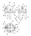
- the plug bridge 1 consists of a substantially flat, approximately diamond-shaped (see top view) base plate 20 made of hard-elastic plastic, and a grounding spring 30 which is positively and non-positively clamped on two diametrically opposite connection sides of the diametrically opposed diamond sides of the base plate 20 (see reference number 31 ) and runs across the underside 21 of the base plate 20 (see reference numeral 32).
- the earthing spring 30 protrudes on both sides over the upper side 22 of the base plate 20, specifically in such a way - compare basic view - that vertically projecting legs 33, 34 result, between which a free space 11 is defined on the upper side 22 of the base plate 20.
- One leg 33 of the earthing spring 30 forms a flat side web for said free space 11; the second leg 34 of the grounding spring 30 is formed and deformed so that a connection socket 35 is formed for the protective conductor connection.
- the transverse clasp 32 of the earthing spring 30 has a tab 36 which, when the earthing spring 30 is mounted, engages and is bent through a corresponding slot in the base plate 20 (see supervision).
- the plug bridge 1 described so far is equipped electrically as follows:
- the base plate 20 protrude at a standardized distance from one another and with a standardized length contact pins 40, 41 with which the plug is ultimately inserted into a mains socket.
- the contact pins 40, 41 are seated in corresponding holes in the base plate 20 and they are (at the second end) extended to the rear so far that they protrude in the form of hollow cylindrical connecting pins 42, 43 into the interior of the space 11 between the legs 33, 34 of the grounding spring 30 .
- the current conductors of a consumer line are mechanically connected, in particular clamped or crimped, with these connecting pins 42, 43.
- the electrical system is ultimately formed by the protective conductor connected to the connecting socket 35 of the earthing spring 30 and the current conductor connected to the connecting pins 42, 43 of the contact pins 40, 41.
- the pins 42, 43 of the current conductor and the connection socket 35 for the protective conductor are arranged approximately in a triangle to one another, the connecting line of the connection pins 42, 43 being directed perpendicular to the axis of the crossbar 32 of the grounding spring 30.
- the plug bridge 1 described so far is state of the art.
- the problems mentioned at the outset can occur, i.e. in the case of individual wires protruding from the side, it can happen that these extend outwards to, possibly even through the sprayed plug head.
- the plug bridge 1 is designed and / or developed as explained and described below.
- An L-shaped molded part 50 projecting over this connecting socket 35 is injection-molded onto the connecting socket 35 for the protective conductor, preferably as an integral part of the injection mold for the base plate 20.
- This molded part 50 protrudes beyond the connecting socket 35 and, together with a support foot 51 together with the base plate 20, forms a one-piece assembly base body.
- connection socket 35 for the protective conductor is thus completely bridged, the head part 52 which is kinked at the free front edge by the L-leg of the molded part 50 lying opposite this connection socket 35.
- An essential feature of the head part 52 of the molded part 50 is a conical through hole which is aligned coaxially with the connecting socket 35 for the protective conductor is. The small diameter of this through hole lies opposite the end face of the connecting socket 35, so that it merges into a funnel-shaped extension toward the free side of the head part 52 of the shaped part 50. Via this funnel-shaped extension, the stripped line end of the protective conductor can be inserted easily and safely and without a single wire of the protective conductor being bent.
- the material thickness of the head part 52 is selected at least so that - depending on the length of the insulation stripped from the protective conductor - this single wire is securely behind the upper edge of the through hole and thus the head part 52 disappears.
- the protective conductor can thus be securely inserted and fixed with the aid of the molded part 50 or the conical through hole, for example by squeezing (crimping).
Landscapes
- Connector Housings Or Holding Contact Members (AREA)
- Coupling Device And Connection With Printed Circuit (AREA)
- Details Of Connecting Devices For Male And Female Coupling (AREA)
Applications Claiming Priority (2)
| Application Number | Priority Date | Filing Date | Title |
|---|---|---|---|
| DE4012583 | 1990-04-20 | ||
| DE4012583A DE4012583C2 (de) | 1990-04-20 | 1990-04-20 | Schutzkontaktstecker mit Grundplatte und Erdungsfeder |
Publications (2)
| Publication Number | Publication Date |
|---|---|
| EP0452761A1 true EP0452761A1 (fr) | 1991-10-23 |
| EP0452761B1 EP0452761B1 (fr) | 1995-06-28 |
Family
ID=6404717
Family Applications (1)
| Application Number | Title | Priority Date | Filing Date |
|---|---|---|---|
| EP91105482A Expired - Lifetime EP0452761B1 (fr) | 1990-04-20 | 1991-04-06 | Fiche à contact de protection avec une plaquette de base et contact de terre à ressort |
Country Status (3)
| Country | Link |
|---|---|
| EP (1) | EP0452761B1 (fr) |
| AT (1) | ATE124577T1 (fr) |
| DE (2) | DE4012583C2 (fr) |
Cited By (1)
| Publication number | Priority date | Publication date | Assignee | Title |
|---|---|---|---|---|
| EP0773606A3 (fr) * | 1995-11-10 | 1998-05-27 | Taller GmbH | Fiche a contact de protection avec une aide d'entree sur la douille de raccordement du conducteur de protection |
Citations (2)
| Publication number | Priority date | Publication date | Assignee | Title |
|---|---|---|---|---|
| FR2538625A1 (fr) * | 1982-12-23 | 1984-06-29 | Cemrep | Fiche a broches pour prise de courant electrique |
| EP0332034A2 (fr) * | 1988-03-09 | 1989-09-13 | Taller GmbH | Pont pour fiche de sécurité comprenant broches creuses cylindriques pour conducteurs de courant et de terre |
Family Cites Families (3)
| Publication number | Priority date | Publication date | Assignee | Title |
|---|---|---|---|---|
| DE8318328U1 (de) * | 1983-06-24 | 1983-11-17 | Taller GmbH Metall- und Kunststofftechnik, 7517 Waldbronn | Kontaktträger für einen Schutzkontaktstecker |
| DE3807716C3 (de) * | 1988-03-09 | 1997-01-16 | Taller Gmbh | Steckerbrücke für einen Schutzkontaktstecker mit hohlzylindrischen Anschlußstiften für die Stromleiter und den Schutzleiter |
| EP0391298B1 (fr) * | 1989-04-07 | 1994-08-24 | Taller GmbH | Connecteur à contact de protection et à une aide d'entrée coordonnée à une douille de raccordement pour le contact de protection |
-
1990
- 1990-04-20 DE DE4012583A patent/DE4012583C2/de not_active Expired - Fee Related
-
1991
- 1991-04-06 EP EP91105482A patent/EP0452761B1/fr not_active Expired - Lifetime
- 1991-04-06 AT AT91105482T patent/ATE124577T1/de not_active IP Right Cessation
- 1991-04-06 DE DE59105823T patent/DE59105823D1/de not_active Expired - Fee Related
Patent Citations (2)
| Publication number | Priority date | Publication date | Assignee | Title |
|---|---|---|---|---|
| FR2538625A1 (fr) * | 1982-12-23 | 1984-06-29 | Cemrep | Fiche a broches pour prise de courant electrique |
| EP0332034A2 (fr) * | 1988-03-09 | 1989-09-13 | Taller GmbH | Pont pour fiche de sécurité comprenant broches creuses cylindriques pour conducteurs de courant et de terre |
Cited By (1)
| Publication number | Priority date | Publication date | Assignee | Title |
|---|---|---|---|---|
| EP0773606A3 (fr) * | 1995-11-10 | 1998-05-27 | Taller GmbH | Fiche a contact de protection avec une aide d'entree sur la douille de raccordement du conducteur de protection |
Also Published As
| Publication number | Publication date |
|---|---|
| DE4012583A1 (de) | 1991-10-24 |
| ATE124577T1 (de) | 1995-07-15 |
| DE59105823D1 (de) | 1995-08-03 |
| EP0452761B1 (fr) | 1995-06-28 |
| DE4012583C2 (de) | 1996-11-28 |
Similar Documents
| Publication | Publication Date | Title |
|---|---|---|
| DE69823726T2 (de) | Elektrischer Kontakt | |
| EP0332034B1 (fr) | Pont pour fiche de sécurité comprenant broches creuses cylindriques pour conducteurs de courant et de terre | |
| DE4229812C1 (de) | Steckerbrücke für einen elektrischen Gerätestecker | |
| DE3807716C3 (de) | Steckerbrücke für einen Schutzkontaktstecker mit hohlzylindrischen Anschlußstiften für die Stromleiter und den Schutzleiter | |
| DE19801896C1 (de) | Steckerbrücke für einen elektrischen Gerätestecker mit integrierter Sicherung | |
| DE4239261A1 (de) | Steckerbrücke für einen elektrischen Gerätestecker mit einem Paar von Stromleiterstiften (Kontaktstiften) und gegebenenfalls einem Schutzleiterstift (Erdstiift) | |
| EP0332035B1 (fr) | Fiche pour appareil électrique, avec une plaque d'ancrage pour les lames de contact | |
| DE4012581C2 (de) | Schutzkontaktstecker mit einem brückenartigen Formteil | |
| EP0452761B1 (fr) | Fiche à contact de protection avec une plaquette de base et contact de terre à ressort | |
| WO2000021162A1 (fr) | Piece rapportee pour connexion electrique tripolaire a fiches pour fiche de raccordement electrique | |
| EP0328992A2 (fr) | Fiche de connexion électrique | |
| EP0391298B1 (fr) | Connecteur à contact de protection et à une aide d'entrée coordonnée à une douille de raccordement pour le contact de protection | |
| DE4012582C2 (de) | Schutzkontaktstecker mit einem integrierten T-förmigen Formteil | |
| DE3809772C1 (en) | Electrical plug connector | |
| DE3839011A1 (de) | Steckerbruecke fuer einen elektrischen geraetestecker mit mindestens einem phasen- und einem nulleiterstift | |
| EP0201035B1 (fr) | Branchement de câble coaxial sur une réglette à ressorts | |
| EP0551068B1 (fr) | Prise de courant modulaire pour appareil électrique | |
| DE3807309A1 (de) | Zweipoliger schutzkontaktstecker (eurostecker) | |
| EP0521190A1 (fr) | Pont à fiches pour une fiche à contact de protection d'un appareil électrique | |
| DE19543235C1 (de) | Schutzkontaktstecker mit einer Einführhilfe für die Anschlußbuchse des Schutzleiters | |
| DE19628725C1 (de) | Steckerbrücke für einen Schutzkontaktstecker mit Einführtrichtern für die Stromleiter | |
| DE102004059162A1 (de) | Elektrisches Gerät mit einer Stromversorgungskupplung | |
| DE8916230U1 (de) | Schutzkontaktstecker mit einer der Anschlußbuchse für den Schutzleiter zugeordneten Einführhilfe |
Legal Events
| Date | Code | Title | Description |
|---|---|---|---|
| PUAI | Public reference made under article 153(3) epc to a published international application that has entered the european phase |
Free format text: ORIGINAL CODE: 0009012 |
|
| AK | Designated contracting states |
Kind code of ref document: A1 Designated state(s): AT BE CH DE DK ES FR IT LI NL SE |
|
| 17P | Request for examination filed |
Effective date: 19911121 |
|
| 17Q | First examination report despatched |
Effective date: 19940128 |
|
| GRAA | (expected) grant |
Free format text: ORIGINAL CODE: 0009210 |
|
| AK | Designated contracting states |
Kind code of ref document: B1 Designated state(s): AT BE CH DE DK ES FR IT LI NL SE |
|
| PG25 | Lapsed in a contracting state [announced via postgrant information from national office to epo] |
Ref country code: DK Effective date: 19950628 Ref country code: BE Effective date: 19950628 Ref country code: ES Free format text: THE PATENT HAS BEEN ANNULLED BY A DECISION OF A NATIONAL AUTHORITY Effective date: 19950628 Ref country code: FR Effective date: 19950628 Ref country code: NL Free format text: LAPSE BECAUSE OF FAILURE TO SUBMIT A TRANSLATION OF THE DESCRIPTION OR TO PAY THE FEE WITHIN THE PRESCRIBED TIME-LIMIT Effective date: 19950628 Ref country code: IT Free format text: LAPSE BECAUSE OF FAILURE TO SUBMIT A TRANSLATION OF THE DESCRIPTION OR TO PAY THE FEE WITHIN THE PRE;WARNING: LAPSES OF ITALIAN PATENTS WITH EFFECTIVE DATE BEFORE 2007 MAY HAVE OCCURRED AT ANY TIME BEFORE 2007. THE CORRECT EFFECTIVE DATE MAY BE DIFFERENT FROM THE ONE RECORDED.SCRIBED TIME-LIMIT Effective date: 19950628 |
|
| REF | Corresponds to: |
Ref document number: 124577 Country of ref document: AT Date of ref document: 19950715 Kind code of ref document: T |
|
| REF | Corresponds to: |
Ref document number: 59105823 Country of ref document: DE Date of ref document: 19950803 |
|
| PG25 | Lapsed in a contracting state [announced via postgrant information from national office to epo] |
Ref country code: SE Effective date: 19950928 |
|
| EN | Fr: translation not filed | ||
| NLV1 | Nl: lapsed or annulled due to failure to fulfill the requirements of art. 29p and 29m of the patents act | ||
| PG25 | Lapsed in a contracting state [announced via postgrant information from national office to epo] |
Ref country code: AT Effective date: 19960406 |
|
| PG25 | Lapsed in a contracting state [announced via postgrant information from national office to epo] |
Ref country code: LI Effective date: 19960430 Ref country code: CH Effective date: 19960430 |
|
| PLBE | No opposition filed within time limit |
Free format text: ORIGINAL CODE: 0009261 |
|
| STAA | Information on the status of an ep patent application or granted ep patent |
Free format text: STATUS: NO OPPOSITION FILED WITHIN TIME LIMIT |
|
| 26N | No opposition filed | ||
| REG | Reference to a national code |
Ref country code: CH Ref legal event code: PL |
|
| PGFP | Annual fee paid to national office [announced via postgrant information from national office to epo] |
Ref country code: DE Payment date: 19971122 Year of fee payment: 7 |
|
| PG25 | Lapsed in a contracting state [announced via postgrant information from national office to epo] |
Ref country code: DE Free format text: LAPSE BECAUSE OF NON-PAYMENT OF DUE FEES Effective date: 19990202 |