EP0452897A2 - Entwicklungsgerät - Google Patents
Entwicklungsgerät Download PDFInfo
- Publication number
- EP0452897A2 EP0452897A2 EP91106122A EP91106122A EP0452897A2 EP 0452897 A2 EP0452897 A2 EP 0452897A2 EP 91106122 A EP91106122 A EP 91106122A EP 91106122 A EP91106122 A EP 91106122A EP 0452897 A2 EP0452897 A2 EP 0452897A2
- Authority
- EP
- European Patent Office
- Prior art keywords
- roller
- stirring roller
- stirring
- disposed
- developer
- Prior art date
- Legal status (The legal status is an assumption and is not a legal conclusion. Google has not performed a legal analysis and makes no representation as to the accuracy of the status listed.)
- Granted
Links
Images



Classifications
-
- G—PHYSICS
- G03—PHOTOGRAPHY; CINEMATOGRAPHY; ANALOGOUS TECHNIQUES USING WAVES OTHER THAN OPTICAL WAVES; ELECTROGRAPHY; HOLOGRAPHY
- G03G—ELECTROGRAPHY; ELECTROPHOTOGRAPHY; MAGNETOGRAPHY
- G03G15/00—Apparatus for electrographic processes using a charge pattern
- G03G15/06—Apparatus for electrographic processes using a charge pattern for developing
- G03G15/08—Apparatus for electrographic processes using a charge pattern for developing using a solid developer, e.g. powder developer
- G03G15/0822—Arrangements for preparing, mixing, supplying or dispensing developer
-
- B—PERFORMING OPERATIONS; TRANSPORTING
- B01—PHYSICAL OR CHEMICAL PROCESSES OR APPARATUS IN GENERAL
- B01F—MIXING, e.g. DISSOLVING, EMULSIFYING OR DISPERSING
- B01F27/00—Mixers with rotary stirring devices in fixed receptacles; Kneaders
- B01F27/05—Stirrers
- B01F27/11—Stirrers characterised by the configuration of the stirrers
- B01F27/114—Helically shaped stirrers, i.e. stirrers comprising a helically shaped band or helically shaped band sections
-
- G—PHYSICS
- G03—PHOTOGRAPHY; CINEMATOGRAPHY; ANALOGOUS TECHNIQUES USING WAVES OTHER THAN OPTICAL WAVES; ELECTROGRAPHY; HOLOGRAPHY
- G03G—ELECTROGRAPHY; ELECTROPHOTOGRAPHY; MAGNETOGRAPHY
- G03G15/00—Apparatus for electrographic processes using a charge pattern
- G03G15/06—Apparatus for electrographic processes using a charge pattern for developing
- G03G15/08—Apparatus for electrographic processes using a charge pattern for developing using a solid developer, e.g. powder developer
- G03G15/0822—Arrangements for preparing, mixing, supplying or dispensing developer
- G03G15/0848—Arrangements for testing or measuring developer properties or quality, e.g. charge, size, flowability
- G03G15/0849—Detection or control means for the developer concentration
- G03G15/0853—Detection or control means for the developer concentration the concentration being measured by magnetic means
-
- G—PHYSICS
- G03—PHOTOGRAPHY; CINEMATOGRAPHY; ANALOGOUS TECHNIQUES USING WAVES OTHER THAN OPTICAL WAVES; ELECTROGRAPHY; HOLOGRAPHY
- G03G—ELECTROGRAPHY; ELECTROPHOTOGRAPHY; MAGNETOGRAPHY
- G03G15/00—Apparatus for electrographic processes using a charge pattern
- G03G15/06—Apparatus for electrographic processes using a charge pattern for developing
- G03G15/08—Apparatus for electrographic processes using a charge pattern for developing using a solid developer, e.g. powder developer
- G03G15/0822—Arrangements for preparing, mixing, supplying or dispensing developer
- G03G15/0877—Arrangements for metering and dispensing developer from a developer cartridge into the development unit
-
- G—PHYSICS
- G03—PHOTOGRAPHY; CINEMATOGRAPHY; ANALOGOUS TECHNIQUES USING WAVES OTHER THAN OPTICAL WAVES; ELECTROGRAPHY; HOLOGRAPHY
- G03G—ELECTROGRAPHY; ELECTROPHOTOGRAPHY; MAGNETOGRAPHY
- G03G15/00—Apparatus for electrographic processes using a charge pattern
- G03G15/06—Apparatus for electrographic processes using a charge pattern for developing
- G03G15/08—Apparatus for electrographic processes using a charge pattern for developing using a solid developer, e.g. powder developer
- G03G15/0822—Arrangements for preparing, mixing, supplying or dispensing developer
- G03G15/0877—Arrangements for metering and dispensing developer from a developer cartridge into the development unit
- G03G15/0879—Arrangements for metering and dispensing developer from a developer cartridge into the development unit for dispensing developer from a developer cartridge not directly attached to the development unit
-
- G—PHYSICS
- G03—PHOTOGRAPHY; CINEMATOGRAPHY; ANALOGOUS TECHNIQUES USING WAVES OTHER THAN OPTICAL WAVES; ELECTROGRAPHY; HOLOGRAPHY
- G03G—ELECTROGRAPHY; ELECTROPHOTOGRAPHY; MAGNETOGRAPHY
- G03G15/00—Apparatus for electrographic processes using a charge pattern
- G03G15/06—Apparatus for electrographic processes using a charge pattern for developing
- G03G15/08—Apparatus for electrographic processes using a charge pattern for developing using a solid developer, e.g. powder developer
- G03G15/0822—Arrangements for preparing, mixing, supplying or dispensing developer
- G03G15/0887—Arrangements for conveying and conditioning developer in the developing unit, e.g. agitating, removing impurities or humidity
- G03G15/0889—Arrangements for conveying and conditioning developer in the developing unit, e.g. agitating, removing impurities or humidity for agitation or stirring
Definitions
- the present invention relates generally to developing apparatus for use in electrophotographic recording machines, and more particularly to a developing apparatus using a developer of the two-component system.
- the disclosed developing apparatus includes a bucket roller rotatably disposed in a development tank or housing and having a plurality of elongate buckets extending between respective peripheral surfaces of a pair of parallel spaced circular disks, a cylindrical tube disposed in the bucket roller and extending along an axis of rotation of the bucket roller, a developer inlet and a developer outlet formed at opposite ends of the cylindrical tube, developer guide members attached to the bucket roller for transporting a developer within the development housing from the developer outlet toward the developer inlet, and a conveyor means disposed in the cylindrical tube for transporting the developer from the developer inlet toward the developer outlet.
- the bucket roller and the transport means serve to transport the developer in the axial direction of the bucket roller while circulating the developer through the inside and the outside of the cylindrical tube, thereby mixing the developer within the bucket roller.
- the bucket roller supplies the developer onto a developing roller.
- U.S. Patent No. 4,033,294 which comprises a plurality of parallel juxtaposed developing rollers and a mixing and transporting roller disposed adjacent to an endmost one of the developing rollers.
- the mixing and transporting roller includes a plurality of spaced-apart auger elements mounted on a drive shaft and a plurality of radially extending flat bars mounted on the periphery of the auger elements.
- the mixing and transporting roller serves to mix a developer while feeding the same in the axial direction and to transport the developer toward the endmost developing roller.
- the pair of circular disks and the plural buckets are manufactured separately. After the circular disks and the buckets are assembled together, the plural developer guide members in the form of fins are attached to each bucket by means of screws, for example.
- the bucket roller is rotatably mounted on the cylindrical tube via a bush of a sintered metal slidably fitted over a fixed bearing mounted on the cylindrical tube.
- Another object of the present invention is to provide a developing apparatus including a stirring device which is capable of stirring a developer without causing an abrasive wear on sliding surfaces of movable parts which are disposed in the developer.
- a further object of the present invention is to provide a developing apparatus which is capable of detecting the density of a developer with accuracy.
- a still further object of the present invention is to provide a developing apparatus which is capable of maintaining the amount of developer uniformly distributed over the entire width of a development box.
- a developing apparatus which comprises: a development box; a developing roller disposed in the development box; a stirring roller parallel spaced apart from the developing roller; a toner replenisher pipe disposed in the stirring roller; and the stirring roller having a substantially hollow cylindrical shape including a plurality of axial ribs extending parallel to a longitudinal axis of the hollow cylindrical stirring roller and disposed equidistantly from the longitudinal axis of the stirring roller, and a plurality of helical blades integral with the axial ribs and skewed relative to the longitudinal axis of the stirring roller, the hollow cylindrical stirring roller being composed of at least two identical segments which are divided by a plane extending through the longitudinal axis of the stirring roller.
- the toner replenisher pipe is an aluminum pipe and the stirring roller is rotatably mounted on the aluminum toner replenisher pipe via a bearing made from aluminum.
- the toner replenisher pipe has a contact surface held in sliding contact with the contact surface of the bering.
- Each of the contact surfaces has a rigid anodized aluminum oxide layer.
- a developing apparatus which comprises: a developing roller disposed in the development box; a first stirring roller parallel spaced apart from the developing roller; a toner replenisher pipe disposed in the stirring roller; a second stirring roller disposed between the development roller and the first stirring roller in parallel spaced relation to the development roller and the first stirring roller; the development box having a bottom surface extending arcuately along the periphery of the first and second stirring rollers between the first and second stirring rollers uniformly spaced from the first and second stirring rollers; and a density sensor disposed on the bottom surface at a portion confronting the first stirring roller.
- the developing apparatus may include a doctor blade for regulating the amount of a developer on the developing roller, and an elongate separator for receiving an excess developer which is removed from the outside surface of the developing roller by the doctor blade and guiding the excess developer onto the second stirring roller, the separator having, on its upper surface, a plurality of first guide plates extending obliquely in a first direction relative to an axis of the developing roller for guiding the excess developer toward one side of a development box, and a plurality of second guide plates extending obliquely in a second direction relative to the axis of the developing roller for guiding the excess development toward the opposite side of the development box, the first guide plates being disposed on a first longitudinal part of the elongate separator, the second guide plates being disposed on a second longitudinal part of the elongate separator, the first longitudinal part being longer than the second longitudinal part.
- FIGs. 1(a) and 1(b) a part of an electrophotographic copying machine including a photoconductive drum 10, a developing unit or apparatus 11 of this invention for developing an electrostatic latent image formed on the photoconductive drum 10, and a toner replenisher 12 for replenishing a toner into the developing apparatus 11.
- the developing apparatus 11 comprises a development box 14 for containing a developer composed of a toner and a carrier, a first stirring roller 15, a second stirring roller 16 and a developing roller 17 which are rotatably disposed in the development box 14.
- the development box 14 is composed of an upper development box member 14A and a lower development box member 14B.
- the first stirring roller 15 receives therein a toner replenisher pipe 19.
- the toner replenisher pipe 19 projects outwardly from an end of the development box 14 and is connected at its front end with an upstanding replenisher pipe 19a to which the toner replenisher 12 is connected for replenishing the toner into the development box 14.
- the toner replenisher pipe 19 has an inner end located close to one side A (hereinafter referred to as "first side") of the development box 14 and having a downwardly opening discharge hole 20.
- the toner replenisher pipe 19 further has an upwardly opening receiving hole 21 disposed near the opposite side B (hereinafter referred to as "second side") of the development box 14.
- a helical screw 22 Disposed within the toner replenisher pipe 19 is a helical screw 22 by means of which the toner replenished from the upstanding replenisher pipe 19a is fed toward the discharge charge hole 20 and, at the same time, the developer received from the receiving hole 21 is conveyed toward the discharge hole 20.
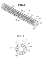
- the first stirring roller 15 is a generally hollow cylinder disposed around the toner replenisher pipe 19 and rotatably mounted on the toner replenisher pipe 19 via a baring 23. As shown in Fig. 3, the first stirring roller 15 is provided with a plurality of axial ribs 15a extending longitudinally along an axis thereof, a plurality of first helical blades 15b extending between the axial ribs 15a and skewed in one direction relative to the axis of the first stirring roller 15, and at least one second helical blade 15c extending between the axial ribs 15a and skewed in the opposite direction relative to the axis of the first stirring roller 15.
- the second helical blade 15c is disposed at only one end of the first stirring roller 15 which is adjacent to the receiving hole 21 in the toner replenisher pipe 19.
- the direction of skew of the first helical blades 15b is opposite to the direction of skew of a thread of the spiral screw 22 disposed within the toner replenisher pipe 19 so that by rotating the first stirring roller 15 and the spiral screw 22 in the same direction as a single unit, the developer can be conveyed in the opposite directions as indicated by the arrows X and Y in Fig. 4.
- the first stirring roller 15 has one end rotatably supported by the toner replenisher pipe 19 via the bearing 23, the opposite end of the first stirring roller 15 being fixedly mounted on a shaft of the spiral screw 22.
- the first stirring roller 15 has a generally hollow cylindrical shape as described above and, as shown in Figs. 5 and 6, the axial ribs 15a are equidistant from the axis of the first stirring roller 15 and circumferentially spaced at equal angular intervals.
- the first helical blades 15b which are skewed in one direction relative to the axis of the first stirring roller 15 are integral with the axial ribs 15a and disposed over the entire length of the first stirring roller 15 except for one end where the second helical blade 15c is disposed.
- the number of second helical blade 15c is considerably smaller than the number of first helical blades 15b.
- first helical blades 15b are skewed in the opposite direction to the thread of the spiral screw 22
- rotation of the first stirring roller 15 in the same direction as the rotating spiral screw 22 causes the first helical blades 15b to transport the developer longitudinally along the outside surface of the toner replenisher pipe 19 in the direction indicated by the arrow X (which is opposite to the direction y of conveyance of the toner by the spiral screw 22).
- the position of the second helical blade 15c which is provided to feed the developer back to the receiving hole 21 is changed depending on the position of the receiving hole 21.
- the first stirring roller 15 of the substantially hollow cylindrical shape is divided into three equal parts or segments 15A, 15B and 15C which are divided by three radial planes extending through corresponding ones of the axial ribs 15a and converging into the longitudinal axis of the first stirring roller 15, as shown in Fig. 7.
- These segments 15A - 15C are identical in construction and injection-molded of a synthetic resin. Since the segments 15A - 15C have a substantially sectoral cross section, they can readily be molded in and then removed from a mold which is composed of a mating pair of mold members separable respectively in radial inward and outward directions of the cross-sectionally sectoral segments 15A - 15C.
- Such mold is simple in construction and inexpensive to manufacture with the result that the segments 15A - 15C can be molded at a low cost.
- the segments 15A - 15C thus molded are bonded together with their axial ribs 15a held in abutment with each other, thus forming a first stirring roller 15.
- each segment 15A - 15C has axial rib halves extending along opposite longitudinal edges thereof, and since the axial rib halves have a relatively large bonding area, bonding process can be performed stably and reliably.
- the helical blades 15b on one segment 15A, 15B or 15C are disposed in staggered relation to the helical blades 15b on the adjacent segment 15B, 15C, 15A.
- the helical blades 15b on one segment 15A, 15B or 15C may be connected end to end with the helical blades 15b on the adjacent segment 15B, 15C, 15A so as to jointly form a single continuous helical blade.
- the bearing 23 (Fig. 4) is properly gripped by and between the segments 15A - 15C in such a manner that it is secured to an end of the first stirring roller 15 composed of the bonded three identical segments 15A - 15C.
- the first stirring roller 15 is composed of three identical segments 15A - 15C.
- the first stirring roller 15 may be composed of two or more than four segments.
- the bearing 23 for rotatably mounting the first stirring roller 15 on the toner replenisher pipe 19 is made of aluminum and comprises a plain bearing which works by sliding action on the toner replenisher pipe 19.
- the bearing 23 has a rigid anodized aluminum oxide layer on its inner peripheral surface which is held in sliding contact with the outside surface of the toner replenisher pipe 19. At least a portion of the outside surface of the toner replenisher pipe 19 which is held in sliding contact with the bearing 23 also has a rigid anodised aluminum oxide layer.
- respective contacting surfaces of the toner replenisher pipe 19 and the bearing 23 are rigid and highly resistant to abrasive wear, so that the developing apparatus 11 is operable reliably over a prolonged period of use even when the carrier in the developer can get into a clearance between the toner replenisher pipe 19 and the bearing 23.
- a toner replenisher pipe 19 of the developing apparatus was made of aluminum and had an outside diameter of 22 mm, while a bearing 23 was made of aluminum and had an inside diameter of 22.3 mm, an outside diameter of 28 mm and a width of 6 mm.
- the toner replenisher pipe 19 had a contact surface composed of a rigid anodised aluminum oxide layer of 30 ⁇ in thickness and having a Vickers hardness of 340.
- the bearing 23 had a contact surface composed of a rigid anodized aluminum oxide layer having a thickness of 30 ⁇ and a Vickers hardness of 340. After a 400 hours running test of the developing apparatus, the contact surfaces of the toner replenisher pipe 17 and the bearing 23 were visually inspected for abrasive wear with the result no particular change was recognized on the contact surfaces.
- a comparative test was made by using a developing apparatus of the type having an aluminum toner replenishing having a contact surface free of anodized aluminum oxide surface layer, and a stirring roller molded of poplyacetal resin directly journaled on the pipe without a bearing.
- a visual inspection performed after a 400 running test of the developing apparatus found that the outer surface of the pipe and the inner surface of the stirring roller had grooves of about 1 mm depth formed by abrasive wear.
- the second stirring roller 16 has a plurality of radial flat bars 16a (eight in the illustrated embodiment).
- the development box 14 has a bottom surface extending between the first and second stirring rollers 15 and 16 arcuately along the periphery of the respective rollers 15, 16 and spaced uniformly from the rollers 15, 16. More specifically, the bottom surface is composed of a first arcuate bottom surface portion 14a extending along a part of the full circumference of the first stirring roller 15 and spaced from the first stirring roller 15 by a gap d (Fig. 1(a)), and a second arcuate bottom surface portion 14b extending along a part of the full circumference of the second stirring roller 16 and spaced from the second stirring roller 16 by the same gap.
- the developer is squeezed from the opposite directions along the first and second bottom surface portions 14a, 14b so as to gather into a space between the first and second stirring rollers 15, 16 and then is mixed sufficiently and uniformly in this space by agitation by the rollers 15, 16. During that time, the developer is conveyed and then mixed continuously without staying or stopping between the first and second stirring rollers 15 and 16.
- the arcuate bottom surface portions 14a, 14b may be composed of a number of flat surfaces joined together to form a substantially arcuate shape.
- a developer density sensor 25 is disposed at the bottom surface portion 14a in confrontation to the first stirring roller 15.
- the developer density sensor 25 is of the inductance type known per se which is constructed to detect a toner-to-carrier mixing ratio depending on the inductance of the developer. Since the bottom surface portion 14a at which the density sensor 25 is disposed is formed arcuately to enable the developer to move continuously and smoothly therealong, the density of the developer can always be detected accurately at the real time by the developer density sensor 25.
- the developer density sensor 25 would always detect the density of the staying part of the developer, thus failing to perform an accurate density measurement of the developer. Such problem never arises in the developing apparatus of this invention because the developer on the developer density sensor 25 is always renewed.
- the density of the developer in the development box 14 can be detected accurately by the density sensor 25 on the real time basis.
- the gap d between the first stirring roller 15 and the density sensor 25 is preferably in the range of from 0.2 to 2.0 mm.
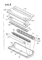
- the developing apparatus 11 further includes an elongate doctor blade 27 for controlling the thickness of the developer carried on the developing roller 17.
- the doctor blade 27, as shown in Fig. 2 includes a pair of positioning pins 28, 28 disposed adjacent to opposite ends thereof.
- the positioning pins 28 are fitted in corresponding positioning holes 14B' in the upper development box member 14B and then a pair of set screws 29 is threaded through the doctor blade 27 into the upper development box member 14B, so that the doctor blade 27 can be attached to a predetermined position on the upper development box member 14B.
- the doctor blade 27 is disposed close to the developing roller 17 with a predetermined gap therebetween when the upper development box member 14B is secured to the lower development box member 14A.
- the doctor blade 27 is adjustable in position relative to the developing roller 17.
- an elongate separator 31 in the form of a flat bar 31 is disposed adjacent to the doctor blade 27 and sloping down toward the first stirring roller 15 for receiving excess developer scraped off from the developing roller 17 and returning the same to the development box 14.
- the separator 31 has on its upper surface a group of first guide plates 32a and a group of second guide plates 32b that are provided for restricting the direction of movement of the excess developer as the developer is returned to the development box 14.
- the first and second guide plates 32a, 32b extend divergently from the developing roller 17 toward the first stirring roller 15.
- the first guide plates 32a which are disposed on a first longitudinal part of the separator 31 located on the first side A of the development box 14, extend obliquely relative to a longitudinal axis of the separator 31 (i.e., a longitudinal axis of the developing roller 17) so that the developer is guided by the first guide plates 32a toward the first side A of the development box 14.
- the second guide plates 32b which are disposed on a second longitudinal portion of the separator 31 located on the second side B of the development box 14, extend obliquely relative to the longitudinal axis of the separator 31 so that the developer is guided by the second guide plates 32b toward the second side B of the development box 14.
- the developer returned from the developing roller 17 is distributed unevenly over the width of the development box 14 and is concentrated toward the opposite sides of the development box 14.
- the first longitudinal part (left-hand port in Fig. 2) of the separator 31 which carries thereon the first guide plates 32a is longer than the second longitudinal part on which the second guide plates 32a are disposed. It was proved by experiments that the length of the first longitudinal part and the length of the second longitudinal part were preferably in the ratio ranging from 1.5 : 1 to 3 : 1.
- the developer When the first stirring roller 15 and the spiral screw 22 in the toner replenisher pipe 19 are rotating, the developer is caused to circulate between the first side A and the second side B of the development box 14. In this instance, the developer tends to gather at the second side B (which is adjacent to the receiving hole 21 in the toner replenisher pipe 19).
- an excess developer which has been removed from the developing roller 17 is returned by the separator 31 into the developing housing 14 in such a manner that the first guide plates 32a deliver a greater amount of developer toward the first side A than the amount of developer which is delivered toward the second side B by the second guide plates 32b.
- Such unevenly distributed return of the excess developer compensates for an uneven distribution of the developer caused by the first stirring roller 15 in the manner stated above.
- the developer is, therefore, distributed uniformly over the entire width of the development box 14.
- the toner replenisher 12 includes a case 34, a geared motor 35 mounted on the case 34, a toner tank holder 36 driven by the geared motor 35, a toner tank 37 held by the toner tank holder 36, a toner discharge pipe 38 connected at its one end with an open end of the toner tank 37, and a spiral screw 38 disposed within the toner discharge pipe 38.
- a toner 40 is supplied from the toner tank 37 into the discharge pipe 38 and thence to the upstanding replenisher pipe 19a.
- the developing apparatus 12 of the foregoing construction operates as follows.
- the photoconductive drum 10, the developing roller 17, the first stirring roller 15 and the second stirring roller 16 are rotating in the direction indicated by the arrows in Fig. 1(a).
- a fresh toner supplied into the toner replenisher pipe 19 is conveyed by the spiral screw 22 in the direction indicated by the arrow Y in Fig. 4, then discharged from the discharge hole 20 adjacent to the first side A of the development box 14, and finally mixed up with the developer existing around the outside surface of the toner replenisher pipe 19.
- the developer is conveyed spirally around the outer surface of the toner replenisher pipe 19 in the direction of the arrow X from the first side A toward the second side B. During that time, the developer is sufficiently stirred up and hence mixed uniformly.
- the developer upon arrival at the receiving hole 21, the developer is forced into the toner replenisher pipe 19, subsequently fed by the spiral screw 22 in the opposite direction Y toward the discharge hole 20, and finally discharged from the discharge hole 20 to the outside of the toner replenisher pipe 19.
- the developer is thus circulated through the outside and the inside of the toner replenisher pipe 19 during which time it is mixed and stirred up uniformly.
- a part of the uniformly mixed developer is advanced by the first stirring roller 15 along the arcuate bottom surface portion 14a toward the second stirring roller 16 which in turn supplies the developer onto the developing roller 17 while stirring the same.
- the developer attracted on the outer surface of the developing roller 17 is regulated in thickness by the doctor blade 27 and then transferred onto the photoconductive drum 10 to develop an electrostatic latent image formed on the photoconductive drum 10.
- An excess amount of developer is scraped off from the developing roller 17 by the doctor blade 27 and then returned by the separator 31 to the receiving side of the second stirring roller 16.
- the guide plates 32a, 32b control the direction of movement of the developer in the manner described above.
- the density sensor 25 detects the density of the developer in a region adjacent to the first stirring roller 15. When the detected density of the developer is lower than a predetermined level, the density sensor 25 issues a command signal to energize the toner replenisher 12 for replenishing the toner until the predetermined toner density level is reached.
- the density sensor 25 is disposed at a position immediately downstream of the first stirring roller 15 and hence is capable of detecting the density of the developer immediately after it is mixed with a fresh toner. The detection of the developer density follows the replenishing of the fresh toner without delay, so that a toner density control can be performed reliably without involving hunting.
Landscapes
- Physics & Mathematics (AREA)
- General Physics & Mathematics (AREA)
- Chemical & Material Sciences (AREA)
- Chemical Kinetics & Catalysis (AREA)
- Dry Development In Electrophotography (AREA)
Applications Claiming Priority (6)
| Application Number | Priority Date | Filing Date | Title |
|---|---|---|---|
| JP2101947A JP2827438B2 (ja) | 1990-04-18 | 1990-04-18 | 現像装置 |
| JP2101954A JPH041680A (ja) | 1990-04-18 | 1990-04-18 | 現像剤攪拌装置 |
| JP101954/90 | 1990-04-18 | ||
| JP101947/90 | 1990-04-18 | ||
| JP2101946A JPH041678A (ja) | 1990-04-18 | 1990-04-18 | 現像装置 |
| JP101946/90 | 1990-04-18 |
Publications (3)
| Publication Number | Publication Date |
|---|---|
| EP0452897A2 true EP0452897A2 (de) | 1991-10-23 |
| EP0452897A3 EP0452897A3 (en) | 1992-10-28 |
| EP0452897B1 EP0452897B1 (de) | 1995-07-12 |
Family
ID=27309586
Family Applications (1)
| Application Number | Title | Priority Date | Filing Date |
|---|---|---|---|
| EP91106122A Expired - Lifetime EP0452897B1 (de) | 1990-04-18 | 1991-04-17 | Entwicklungsgerät |
Country Status (3)
| Country | Link |
|---|---|
| US (1) | US5189474A (de) |
| EP (1) | EP0452897B1 (de) |
| DE (1) | DE69111123T2 (de) |
Cited By (2)
| Publication number | Priority date | Publication date | Assignee | Title |
|---|---|---|---|---|
| EP0634706A1 (de) * | 1993-07-12 | 1995-01-18 | Agfa-Gevaert N.V. | Elektrostatographisches Gerät |
| EP0827042A3 (de) * | 1996-08-24 | 1998-07-01 | Samsung Electronics Co., Ltd. | Entwicklungseinheit für elektrophotographisches Gerät |
Families Citing this family (14)
| Publication number | Priority date | Publication date | Assignee | Title |
|---|---|---|---|---|
| JPH0635317A (ja) * | 1992-07-16 | 1994-02-10 | Fuji Xerox Co Ltd | 電子写真用一成分現像装置 |
| JP3319844B2 (ja) * | 1993-12-27 | 2002-09-03 | 株式会社リコー | 現像剤撹拌装置 |
| JPH0830097A (ja) * | 1994-07-19 | 1996-02-02 | Fuji Xerox Co Ltd | トナー搬送装置 |
| US5682584A (en) * | 1994-07-28 | 1997-10-28 | Minolta Co., Ltd. | Developer mixing and transporting device |
| JPH0934245A (ja) * | 1995-07-19 | 1997-02-07 | Hewlett Packard Co <Hp> | 電子写真術用材料移動ローラ |
| US6179458B1 (en) * | 1996-11-01 | 2001-01-30 | E. I. Du Pont De Nemours And Company | Forming a solution of fluids having low miscibility and large-scale differences in viscosity |
| DE19742668A1 (de) * | 1997-09-26 | 1999-04-22 | Oce Printing Systems Gmbh | Entwicklerstation mit Schaufelwalzenanordnung zur Querdurchmischung des Entwicklergemisches |
| JP4089864B2 (ja) * | 2001-08-07 | 2008-05-28 | 三星電子株式会社 | 粉体攪拌装置 |
| USD479025S1 (en) | 2002-07-30 | 2003-08-26 | Walter W. Pytlewski | Roller for tile grouting system bucket |
| CN101382757A (zh) * | 2007-09-06 | 2009-03-11 | 京瓷美达株式会社 | 具有调色剂搅拌功能的调色剂容器 |
| JP4613228B2 (ja) * | 2008-06-30 | 2011-01-12 | シャープ株式会社 | 現像装置及び画像形成装置 |
| JP5047336B2 (ja) * | 2010-07-15 | 2012-10-10 | シャープ株式会社 | 現像装置およびそれを備えた画像形成装置 |
| US8655231B2 (en) * | 2011-07-13 | 2014-02-18 | Eastman Kodak Company | Electrophotographic developer toner replenishment apparatus |
| CN111183399A (zh) | 2017-10-05 | 2020-05-19 | 惠普发展公司,有限责任合伙企业 | 用于打印材料容器的材料输送构件 |
Family Cites Families (21)
| Publication number | Priority date | Publication date | Assignee | Title |
|---|---|---|---|---|
| US4033294A (en) * | 1972-05-22 | 1977-07-05 | Xerox Corporation | Developer mixing and transporting auger for magnetic brush developing apparatus |
| US4025179A (en) * | 1975-05-05 | 1977-05-24 | Xerox Corporation | Passive cross mixing system |
| JPS607791B2 (ja) * | 1977-12-29 | 1985-02-27 | 日立金属株式会社 | 現像剤混合手段を有する現像装置 |
| US4361109A (en) * | 1980-02-12 | 1982-11-30 | Ricoh Company, Ltd. | Developer crossmixing apparatus |
| JPS57141665A (en) * | 1982-01-19 | 1982-09-02 | Minolta Camera Co Ltd | Developing device for electrostatic latent image |
| JPS58149079A (ja) * | 1982-03-01 | 1983-09-05 | Minolta Camera Co Ltd | 静電潜像現像装置 |
| JPS5997166A (ja) * | 1982-11-27 | 1984-06-04 | Toshiba Corp | 現像剤撹拌装置 |
| JPS59231561A (ja) * | 1983-06-14 | 1984-12-26 | Minolta Camera Co Ltd | 静電潜像現像装置 |
| JPS6022153A (ja) * | 1983-07-18 | 1985-02-04 | Mita Ind Co Ltd | 静電潜像現像装置 |
| US4491409A (en) * | 1983-07-25 | 1985-01-01 | Minnesota Mining And Manufacturing Company | Electrographic copy paper support |
| JPS6233583A (ja) * | 1985-08-06 | 1987-02-13 | キッコーマン株式会社 | 分級機の分級スクリ−ン装置 |
| JPS6273284A (ja) * | 1985-09-27 | 1987-04-03 | Fuji Xerox Co Ltd | 複写機の磁気ブラシ現像装置 |
| JPS62209573A (ja) * | 1986-03-11 | 1987-09-14 | Konishiroku Photo Ind Co Ltd | 複写機等の現像装置 |
| JPS62293267A (ja) * | 1986-06-13 | 1987-12-19 | Fujitsu Ltd | 現像装置 |
| JPH058610Y2 (de) * | 1986-11-18 | 1993-03-03 | ||
| US4906104A (en) * | 1987-03-03 | 1990-03-06 | Minolta Camera Kabushiki Kaisha | Agitating and supplying device and a mold for molding same |
| US4956679A (en) * | 1987-04-25 | 1990-09-11 | Minolta Camera Kabushiki Kaisha | Image forming apparatus |
| US4928144A (en) * | 1987-05-31 | 1990-05-22 | Ricoh Kk | Developing device for a color image forming apparatus |
| US4825244A (en) * | 1987-11-23 | 1989-04-25 | Eastman Kodak Company | Development station with improved mixing and feeding apparatus |
| US5005517A (en) * | 1988-07-06 | 1991-04-09 | Minolta Camera Kabushiki Kaisha | Developing device |
| US4980724A (en) * | 1989-06-15 | 1990-12-25 | Xerox Corporation | Developer material crossmixing apparatus |
-
1991
- 1991-04-17 EP EP91106122A patent/EP0452897B1/de not_active Expired - Lifetime
- 1991-04-17 DE DE69111123T patent/DE69111123T2/de not_active Expired - Fee Related
- 1991-04-18 US US07/686,973 patent/US5189474A/en not_active Expired - Lifetime
Cited By (3)
| Publication number | Priority date | Publication date | Assignee | Title |
|---|---|---|---|---|
| EP0634706A1 (de) * | 1993-07-12 | 1995-01-18 | Agfa-Gevaert N.V. | Elektrostatographisches Gerät |
| BE1007265A4 (nl) * | 1993-07-12 | 1995-05-02 | Agfa Gevaert Nv | Een electrostatografische ontwikkelinrichting. |
| EP0827042A3 (de) * | 1996-08-24 | 1998-07-01 | Samsung Electronics Co., Ltd. | Entwicklungseinheit für elektrophotographisches Gerät |
Also Published As
| Publication number | Publication date |
|---|---|
| DE69111123T2 (de) | 1995-11-09 |
| DE69111123D1 (de) | 1995-08-17 |
| EP0452897B1 (de) | 1995-07-12 |
| EP0452897A3 (en) | 1992-10-28 |
| US5189474A (en) | 1993-02-23 |
Similar Documents
| Publication | Publication Date | Title |
|---|---|---|
| EP0452897B1 (de) | Entwicklungsgerät | |
| DE69717545T2 (de) | Tonerzuführeinrichtung und Bilderzeugungsgerät | |
| JP4615921B2 (ja) | 画像形成装置 | |
| US9458879B2 (en) | Transporting member, developing device, and image forming apparatus | |
| US20090060591A1 (en) | Developing roller, developing device, process cartridge, and image forming apparatus | |
| JP4410983B2 (ja) | 現像装置及び画像形成装置 | |
| US4956675A (en) | Ribbon blender for a development apparatus with self adjusting inner and outer ribbons | |
| EP0967533B1 (de) | Bilderzeugungsgerät | |
| EP0437864B1 (de) | Entwicklungsgerät für elektrostatische latente Bilder | |
| US4690096A (en) | Magnetic brush development apparatus having a gating and metering mechanism | |
| US10824095B2 (en) | Transporting member, developing device, and image forming apparatus | |
| JPH0218585A (ja) | 現像装置 | |
| JPH0553438A (ja) | 現像装置 | |
| US20220004119A1 (en) | Developing device | |
| US10054872B2 (en) | Image forming apparatus having removable developing units | |
| JP3311557B2 (ja) | 現像ユニット | |
| JP3434118B2 (ja) | 現像剤撹拌装置 | |
| JPH0234695Y2 (de) | ||
| JP2003107859A (ja) | 現像装置 | |
| JP3463023B2 (ja) | 搬送羽根およびそれを含む現像装置 | |
| JP2998170B2 (ja) | 現像剤撹拌ローラ及びこれを用いた電子写真記録装置 | |
| EP0816935B1 (de) | Vorrichtung zum Entwickeln eines latenten elektrostatischen Bildes | |
| US5809383A (en) | Electrostatic developing device | |
| JP2808536B2 (ja) | 供給ローラ | |
| JP7131151B2 (ja) | 現像装置、画像形成装置 |
Legal Events
| Date | Code | Title | Description |
|---|---|---|---|
| PUAI | Public reference made under article 153(3) epc to a published international application that has entered the european phase |
Free format text: ORIGINAL CODE: 0009012 |
|
| 17P | Request for examination filed |
Effective date: 19910417 |
|
| AK | Designated contracting states |
Kind code of ref document: A2 Designated state(s): DE FR GB |
|
| PUAL | Search report despatched |
Free format text: ORIGINAL CODE: 0009013 |
|
| AK | Designated contracting states |
Kind code of ref document: A3 Designated state(s): DE FR GB |
|
| 17Q | First examination report despatched |
Effective date: 19940315 |
|
| GRAA | (expected) grant |
Free format text: ORIGINAL CODE: 0009210 |
|
| AK | Designated contracting states |
Kind code of ref document: B1 Designated state(s): DE FR GB |
|
| REF | Corresponds to: |
Ref document number: 69111123 Country of ref document: DE Date of ref document: 19950817 |
|
| ET | Fr: translation filed | ||
| PLBE | No opposition filed within time limit |
Free format text: ORIGINAL CODE: 0009261 |
|
| STAA | Information on the status of an ep patent application or granted ep patent |
Free format text: STATUS: NO OPPOSITION FILED WITHIN TIME LIMIT |
|
| 26N | No opposition filed | ||
| REG | Reference to a national code |
Ref country code: GB Ref legal event code: IF02 |
|
| PGFP | Annual fee paid to national office [announced via postgrant information from national office to epo] |
Ref country code: FR Payment date: 20060410 Year of fee payment: 16 |
|
| PGFP | Annual fee paid to national office [announced via postgrant information from national office to epo] |
Ref country code: GB Payment date: 20060412 Year of fee payment: 16 |
|
| PGFP | Annual fee paid to national office [announced via postgrant information from national office to epo] |
Ref country code: DE Payment date: 20060413 Year of fee payment: 16 |
|
| GBPC | Gb: european patent ceased through non-payment of renewal fee |
Effective date: 20070417 |
|
| PG25 | Lapsed in a contracting state [announced via postgrant information from national office to epo] |
Ref country code: DE Free format text: LAPSE BECAUSE OF NON-PAYMENT OF DUE FEES Effective date: 20071101 |
|
| PG25 | Lapsed in a contracting state [announced via postgrant information from national office to epo] |
Ref country code: GB Free format text: LAPSE BECAUSE OF NON-PAYMENT OF DUE FEES Effective date: 20070417 |
|
| PG25 | Lapsed in a contracting state [announced via postgrant information from national office to epo] |
Ref country code: FR Free format text: LAPSE BECAUSE OF NON-PAYMENT OF DUE FEES Effective date: 20070430 |