EP0452899B1 - Füllvorrichtung - Google Patents
Füllvorrichtung Download PDFInfo
- Publication number
- EP0452899B1 EP0452899B1 EP91106129A EP91106129A EP0452899B1 EP 0452899 B1 EP0452899 B1 EP 0452899B1 EP 91106129 A EP91106129 A EP 91106129A EP 91106129 A EP91106129 A EP 91106129A EP 0452899 B1 EP0452899 B1 EP 0452899B1
- Authority
- EP
- European Patent Office
- Prior art keywords
- gas pipe
- container
- housing
- gas
- liquid
- Prior art date
- Legal status (The legal status is an assumption and is not a legal conclusion. Google has not performed a legal analysis and makes no representation as to the accuracy of the status listed.)
- Expired - Lifetime
Links
- 239000007788 liquid Substances 0.000 claims description 76
- 238000007789 sealing Methods 0.000 claims description 23
- 238000007599 discharging Methods 0.000 claims description 3
- 238000002347 injection Methods 0.000 description 25
- 239000007924 injection Substances 0.000 description 25
- 230000006835 compression Effects 0.000 description 10
- 238000007906 compression Methods 0.000 description 10
- 238000004140 cleaning Methods 0.000 description 5
- 230000000694 effects Effects 0.000 description 4
- 230000004308 accommodation Effects 0.000 description 3
- 238000000034 method Methods 0.000 description 2
- 230000002265 prevention Effects 0.000 description 2
- 238000009924 canning Methods 0.000 description 1
- 230000003028 elevating effect Effects 0.000 description 1
- 230000000717 retained effect Effects 0.000 description 1
Images


Classifications
-
- B—PERFORMING OPERATIONS; TRANSPORTING
- B67—OPENING, CLOSING OR CLEANING BOTTLES, JARS OR SIMILAR CONTAINERS; LIQUID HANDLING
- B67C—CLEANING, FILLING WITH LIQUIDS OR SEMILIQUIDS, OR EMPTYING, OF BOTTLES, JARS, CANS, CASKS, BARRELS, OR SIMILAR CONTAINERS, NOT OTHERWISE PROVIDED FOR; FUNNELS
- B67C3/00—Bottling liquids or semiliquids; Filling jars or cans with liquids or semiliquids using bottling or like apparatus; Filling casks or barrels with liquids or semiliquids
- B67C3/02—Bottling liquids or semiliquids; Filling jars or cans with liquids or semiliquids using bottling or like apparatus
- B67C3/06—Bottling liquids or semiliquids; Filling jars or cans with liquids or semiliquids using bottling or like apparatus using counterpressure, i.e. filling while the container is under pressure
-
- B—PERFORMING OPERATIONS; TRANSPORTING
- B67—OPENING, CLOSING OR CLEANING BOTTLES, JARS OR SIMILAR CONTAINERS; LIQUID HANDLING
- B67C—CLEANING, FILLING WITH LIQUIDS OR SEMILIQUIDS, OR EMPTYING, OF BOTTLES, JARS, CANS, CASKS, BARRELS, OR SIMILAR CONTAINERS, NOT OTHERWISE PROVIDED FOR; FUNNELS
- B67C3/00—Bottling liquids or semiliquids; Filling jars or cans with liquids or semiliquids using bottling or like apparatus; Filling casks or barrels with liquids or semiliquids
- B67C3/02—Bottling liquids or semiliquids; Filling jars or cans with liquids or semiliquids using bottling or like apparatus
- B67C3/22—Details
- B67C3/26—Filling-heads; Means for engaging filling-heads with bottle necks
- B67C3/2614—Filling-heads; Means for engaging filling-heads with bottle necks specially adapted for counter-pressure filling
- B67C3/2617—Filling-heads; Means for engaging filling-heads with bottle necks specially adapted for counter-pressure filling the liquid valve being opened by mechanical or electrical actuation
- B67C3/262—Filling-heads; Means for engaging filling-heads with bottle necks specially adapted for counter-pressure filling the liquid valve being opened by mechanical or electrical actuation and the filling operation stopping when the liquid rises to a level at which it closes a vent opening
-
- B—PERFORMING OPERATIONS; TRANSPORTING
- B67—OPENING, CLOSING OR CLEANING BOTTLES, JARS OR SIMILAR CONTAINERS; LIQUID HANDLING
- B67C—CLEANING, FILLING WITH LIQUIDS OR SEMILIQUIDS, OR EMPTYING, OF BOTTLES, JARS, CANS, CASKS, BARRELS, OR SIMILAR CONTAINERS, NOT OTHERWISE PROVIDED FOR; FUNNELS
- B67C3/00—Bottling liquids or semiliquids; Filling jars or cans with liquids or semiliquids using bottling or like apparatus; Filling casks or barrels with liquids or semiliquids
- B67C3/02—Bottling liquids or semiliquids; Filling jars or cans with liquids or semiliquids using bottling or like apparatus
- B67C3/22—Details
- B67C3/26—Filling-heads; Means for engaging filling-heads with bottle necks
- B67C2003/2657—Filling-heads; Means for engaging filling-heads with bottle necks specially adapted for filling cans
-
- Y—GENERAL TAGGING OF NEW TECHNOLOGICAL DEVELOPMENTS; GENERAL TAGGING OF CROSS-SECTIONAL TECHNOLOGIES SPANNING OVER SEVERAL SECTIONS OF THE IPC; TECHNICAL SUBJECTS COVERED BY FORMER USPC CROSS-REFERENCE ART COLLECTIONS [XRACs] AND DIGESTS
- Y10—TECHNICAL SUBJECTS COVERED BY FORMER USPC
- Y10S—TECHNICAL SUBJECTS COVERED BY FORMER USPC CROSS-REFERENCE ART COLLECTIONS [XRACs] AND DIGESTS
- Y10S141/00—Fluent material handling, with receiver or receiver coacting means
- Y10S141/01—Magnetic
Definitions
- the present invention relates in general to a filling apparatus, and more particularly to a liquid filling apparatus applicable to a canning machine or the like.
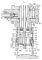
- gas switching valve main bodies 953 are fixedly secured at predetermined intervals to a bottom of an annular tank 932 for accommodating liquid by means of bolts 954, and also on the bottom surface of the gas switching valve main body 953 is present a housing 901 fixedly secured to the former by means of bolts 955. Liquid to be filled in a container 934 is subjected to a gas pressure simultaneously with accommodation within an inner space 933 of the aforementioned annular tank 932.
- the surface of the liquid is held lower than the height of a free inner space 933 of the annular tank 932 so that a gas space may extend above the surface.
- a holding cylinder 904 which is formed as a hollow cylinder and serves to position and seal the container 934.
- the holding member 904 is held in tight contact with the outer surface of the housing 901 at a location indicated by reference numeral 935, and on its central side surface portion, it has a recess 936 which is engageable with a fork-shaped tool (not shown) for vertically moving this holding member 904 with respect to the housing 901.
- the holding member 904 is provided with a positioning conical portion 937 formed in a tapered surface inwardly from its bottom end. At the inner end portion of this positioning conical portion 937 is disposed a sealing element 938 serving as a seal member for the container 934.
- the container 934 is placed on a lower support table 939 fixed to the housing 901, and it is constrained at a position centered with respect to the filling apparatus by means of a semi-circular guide section 940.
- the housing 901 has an inner piece 941 on its inside, and between the inner piece 941 and the housing 901 is formed a liquid feed passageway 942 of nearly annular shape.
- An injection port 926 is provided at the bottom of the liquid feed passageway 942, and a liquid jet flow is led from the injection port 926 to an inner wall surface of the container 934, where the liquid flows towards the bottom as forming a laminar flow as much as possible.
- the housing 901 has a step portion 943 on its inside, and this also forms an upper limit of the inner piece 941.
- the liquid feed passageway 942 terminates here, and since this passageway must be sealed here, an annular liquid valve 944 is disposed above this step portion 943, and this annular liquid valve 944 can be vertically moved by a pipe 946.
- a compression spring (not shown).
- An inner space and an outer space 950 of the pipe 946 are communicated with the inside 933 of the liquid space of the annular tank 932 via holes 945.
- On the inside of the inner piece 941 is disposed a gas pipe 951, a step portion 951a is provided at the top end portion of the gas pipe 951, a flange 951b is provided at a lower portion thereof, and a stopper piece 970 is fixed by a retaining ring 971 on the inside of the proximity of the center of the inner piece 941 to serve as a positioning member in the downward direction for the gas pipe 951.
- a spring 972 On the other hand, on the outside of the gas pipe 951 is disposed a spring 972, the bottom end of the spring 972 is fitted and secured to the upper surface of the flange 951b of the gas pipe 951, its top end butts against the stopper piece 970, and thus the spring 972 normally biases the inner piece 941 of the housing 901 in the downward direction.
- a free end portion 986 of a bend member 985 fits around an outer circumference of the gas pipe 951 without being fixedly secured thereto, and the bend member 985 has its the other arm 989 connected to the holding member 904 by means of a pin 925 and a nut 924.
- An upper surface 987 of the free end portion 986 of the bend member 985 and a lower surface of the gas pipe flange 951b are disposed with a predetermined gap space S retained therebetween.
- the gas pipe 951 reaches the inner space 957 of the gas passageway 956, this gas passageway extends upwards up to the inside of the gas space in the annular tank 932 and terminates at the above of the liquid surface, and thereby the inside of the gas pipe 951 communicates with the inner gas space of the annular tank 932.
- a gas valve (not shown).
- annular chamber 959 Between the outer surface of the housing 901 and the inner surface of the holding member 904 is provided an annular chamber 959, this annular chamber 959 communicates via a passageway 962 with a release valve 961 which can be opened externally by means of a tapet 960, and the annular chamber 959 communicates via a passageway 963 with an inner space of the sealing element 938.
- the step portion 951a of the gas pipe 951 is restrained from slipping out downwards by the stopper piece 970 and the retaining ring 971 at the inside portion in the proximity of the center of the inner piece 941. Consequently, when the gas pipe 951 is to be replaced, the retaining ring 971 must be removed by inserting a special tool into a narrow gap space between the inside portion of the inner piece 941 and the outer circumference of the spring 972. This work necessitates a lot of time.
- a gas pipe of a filling apparatus which determines a filled volume within a container, is slidably fitted into an inner piece of a housing, and a step portion for positioning the gas pipe with respect to the downward direction is provided at an injection port.
- a circular ring slidably fitted on the inner circumference side of a holding member and a spring for normally biasing the same circular ring in the downward direction, and also positioning in the downward direction is carried out by making a flange at the middle portion of the gas pipe butt against the step portion provided at the injection port.
- a free end of a bend member fixedly secured to the above-mentioned circular ring and the outer circumference of the above-described gas pipe are unslidably fitted to each other, and a desired gap space is provided between the bottom of the circular ring and a top surface of a conical cylinder.
- the large stroke generated upon raising the holding member when a container is taken out from the filling apparatus is made not to propagate to the aforementioned spring.
- a gas pipe for determining a filled amount within a container is slidably fitted in a housing inner piece fixedly secured to a housing in a coaxial manner, at a middle portion of the above-mentioned gas pipe is provided a flange, and at the bottom portion of the above-described housing inner piece is provided a step portion adapted to be engaged with the flange at the middle portion of the aforementioned gas pipe for limiting the position in the downward direction of the above-mentioned gas pipe.
- a plate-shaped flange having a longer diameter and a shorter diameter along two orthogonal directions is provided at a middle portion of a gas pipe, while at a portion fixed to a housing (for instance, an inner circumferential portion of an injection port) is provided a step having a slot-like opening whose width is narrower than a length of the gas pipe longer diameter flange of the above-described gas pipe middle flange and broader than a width of the same longer diameter flange.
- the present invention can offer the following effects and advantages:
- the bend member pushes up the gas pipe. Accordingly, the large stroke generated when the above-mentioned holding member is raised would not propagate to the aforementioned spring.
- the gas pipe is inhibited from rotation by the bend member fixedly secured to the holding member, the phase relationship between the longer diameter flange portion of the gas pipe and the slot-like opening provided at the inner circumferential portion of the above-mentioned injection port, and therefore, prevention of the gas pipe from slipping out downwards can be insured.
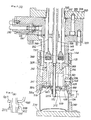
- gas switching valve main bodies 153 are fixedly secured at predetermined intervals to a bottom of an annular tank 132 for accommodating liquid, by means of bolts 154, and also on the bottom surface of the gas switching valve main body 153 is present a housing 101 fixedly secured to the former by means of bolts 155.
- Liquid to be filled in a container 134 is subjected to a gas pressure simultaneously with accommodation within an inner space 133 of the aforementioned annular tank 132.
- the surface of the liquid is made lower than the height of a free inner space 133 of the annular tank 132 so that a gas space may extend above the surface.
- a holding member 104 and a positioning conical cylinder 137 which are formed as hollow cylinders and serve to position and seal the container 134.
- the holding cylinder 104 and the positioning conical cylinder 137 are connected at a threaded portion 125.
- a circular ring 130 On the inside of these members is slidably assembled a circular ring 130 with a resilient force of a spring 172 exerted downwardly.
- the holding member 104 is held in tight contact with an outer surface of the housing 101 at the location indicated by reference numeral 135, and it has a recessed portion 136 engageable with a fork-shaped tool (not shown) for vertically moving this holding member 104 with respect to the housing 101, on the side surface of its central portion.
- the positioning conical cylinder 137 has a positioning conical portion 137a formed in a tapered surface extending inwardly from its bottom. At the inner end portion of this positioning cone portion 137a is disposed a sealing element 138 serving as a seal member for the container 134.
- the container 134 is placed on a lower support table 139 fixed to the housing 101, and it is constrained at a position centered with respect to the filling apparatus by means of a semi-circular guide section 140.
- the housing 101 has an inner piece 141 on its inside, and between the inner piece 141 and the housing 101 is formed a liquid feed passageway 142 of nearly annular shape.
- An injection port 126 is provided at the bottom of the liquid feed passageway 142, and a liquid jet flow is led from the injection port 126 to an inner wall surface of the container 134, where the liquid flows towards the bottom while forming a laminar flow as much as possible.
- the housing 101 has a step portion 143 on its inside, and this also forms an upper limit of the inner piece 141.
- the liquid feed passageway 142 terminates here, and since this passageway must be sealed here, an annular liquid valve 144 is disposed above this step portion 143, and this annular liquid valve 144 can be vertically moved by a pipe 146.
- a compression spring (not shown).
- An inner space and an outer space 150 of the pipe 146 are communicated with the inside 133 of the liquid space of the annular tank 132 via holes 145.
- On the inside of the inner piece 141 is disposed a gas pipe 151, a flange 151a is provided on the gas pipe 151, a step portion 170 is provided on the inside portion in the proximity of the center of the injection port 126, and these serve to position the gas pipe 151 in the downward direction.
- a free and portion 256 of a bend member 255 is fixedly secured to an outer circumference of the gas pipe 151, and the bend member 255 has the other arm 229 thereof connected to the annular ring 130 by means of bolts 124.
- the bottom 257 of the circular ring 130 and the top surface 137b of the positioning conical cylinder 137 are disposed so as to maintain a predetermined gap space S therebetween.
- the gas pipe 151 reaches an inner space 157 of a gas passageway 156, this gas passageway 156 extends upwards up to the inside of gas space in the annular tank 132 and terminates at the above of the liquid surface, and thereby the inside of the gas pipe 151 communicates with the inner gas space of the annular tank 132.
- a gas valve (not shown).
- this annular chamber 159 communicates via a passageway 162 with a release valve 161 which can be opened externally by means of a tapet 160, and the annular chamber 159 communicates via a passageway 163 with an inner space of the sealing element 138.
- the above-described filling apparatus operates in the following manner. That is, an empty container 134 having its mouth opened is carried in by a conveying device not shown, this is transported onto the lower support table 139, and it is centered with respect to the filling apparatus by means of the guide section 140. By means of a fork-shaped tool (not shown) that is engageable with the recessed portion 136 of the above-described holding member 104, this holding member 104 and the positioning conical cylinder 137 are moved downwards and ride on the container 134.
- a gas valve (not shown) within the gas passageway 156 is opened by a control device not shown, hence gas is fed from the inner space 133 of the annular tank 132 through the gas passageway 156 and the gas pipe 151 to the inside of the container 134, the inside of the liquid feed passageway 142, the inside of the passageways 162 and 163, and the inside of a chamber 159, and since all these members are communicated with one another, they would become an equal pressure.
- an annular liquid valve 144 opens automatically under an action of a spring, as a result liquid reaches into the container through the liquid feed passageway 142 and the injection port 126, and the container 134 is filled until a liquid surface reaches the mouth of the gas pipe 151.
- a filled amount within the container 134 is determined by a depth H of the lower surface of the gas pipe 151 as measured from the upper edge of the container 134 butting against the above-described sealing element 138.
- the above-mentioned depth H can be varied only by differently setting the annular tank 132 with respect to the lower support table 139 by vertical movement means not shown.
- annular liquid valve 144 and a gas valve (not shown) in the gas passageway 156 are mechanically closed by a control device not shown, and the inner space of the container is perfectly shut from the inner space of the annular tank 132 and the atmospheric air.
- the release valve 161 is opened as a result of actuation of the tapet 160 by means of a cam not shown, and a pressure in the inner space of the container 134 is released through the passageway 163, the chamber 159, the passageway 162 and the release valve 161.
- the gap space S between the lower surface 257 of the circular ring 130 subjected to a downward force of the spring 172 and the upper surface 137b of the positioning conical cylinder 137 is gradually narrowed, eventually they would butt against each other, and subsequently, the gas pipe 151 is raised high from the upper surface of the container integrally with the holding member 104 and the positioning conical cylinder 137, simultaneously with the bend member 255 and the circular ring 130.
- the container 134 is transferred from a rotary zone of a filling machine to a rotary zone of a sealing machine (not shown).
- gas switching valve main bodies 353 are fixedly secured at predetermined intervals to a bottom of an annular tank 332 for accommodating liquid, by means of bolts 354.
- a housing 301 fixedly secured to the former by means of bolts 355.
- Liquid to be filled in a container 334 is subjected to a gas pressure simultaneously with accommodation within an inner space 333 of the above-mentioned annular tank 332.
- the surface of the liquid is made lower than the height of a free inner space 333 of the annular tank 332 so that a gas space may extend above the surface.
- a holding cylinder 304 which is formed in a hollow cylinder and serves to position and seal the container 334.
- the holding cylinder 304 is held in tight contact with an outer surface of the housing 301 at the location indicated by reference numeral 335, and it has a recessed portion 336 engageable with a fork-shaped tool (not shown) for vertically moving this holding cylinder 304 with respect to the housing 301, on the side surface of its central portion.
- the holding cylinder 304 has a positioning conical portion 337 formed in a tapered surface extending inwardly from its bottom. At the inner top end portion of this positioning conical portion 337 is disposed a sealing element 338 serving as a seal member for the container 334.
- the container 334 is placed on a lower support table 339 fixed to the housing 301, and it is constrained at a position centered with respect to the filling apparatus by means of a semi-circular guide section 340.
- the housing 301 has an inner piece 341 on its inside, and between the inner piece 341 and the housing 301 is formed a liquid feed passageway 342 of nearly annular shape.
- An injection port 326 is provided at the bottom of the liquid feed passageway 342, and a liquid jet flow is led from the injection port 326 to an inner wall surface of the container 334, where the liquid flows towards the bottom while forming a laminar flow as much as possible.
- the housing 301 has a step portion 343 on its inside, and this also forms an upper limit of the inner piece 341.
- the liquid feed passageway 342 terminates here, and since this passageway must be sealed here, an annular liquid valve 344 is disposed above the step portion 343, and this annular liquid valve 344 can be moved vertically by a pipe 346.
- a compression spring (not shown).
- An inner space and an outer space 350 of the pipe 346 are communicated with the inside 333 of the liquid space of the annular tank 332 via holes 345.
- On the inside of the inner piece 341 is disposed a gas pipe 351, a gas pipe middle flange 351a is provided at the middle portion of the gas pipe, while at the lower portion is provided a gas pipe lower flange 351b, and a step portion 326a is provided at an inner circumferential portion of the injection port 326 which is fixedly secured to the housing 301 as well as the above-mentioned inner piece 341, and this step portion 326a serves to position the gas pipe 351 in the downward direction.
- a spring 372 On the other hand, on the outside of the gas pipe 351 under the middle flange 351a is disposed a spring 372, the bottom end of the spring 372 is fitted and secured to an upper surface of the gas pipe lower flange 351b, while the top end thereof butts against a lower surface of a free end portion 456 of a bend member 455 fixedly secured to the above-mentioned holding cylinder 304, and the gas pipe 351 is normally biased downwards against the injection port 326 fixedly secured to the housing 301.
- a free end portion 456 of the bend member 455 slidably fits around the outer circumference of the gas pipe 351 under the middle flange, and the bend member 455 has the other arm 429 thereof connected to the holding cylinder 304 by means of a pin 325 and a nut 324.
- the gas pipe 351 reaches the inner space 357 of the gas passageway 356, this gas passageway 356 extends upwards up to the inside of the gas space of the annular tank 332 and terminates at the above of the liquid surface, and thereby the inside of the gas pipe 351 communicates with the inside of the annular tank 332.
- a gas valve (not shown). Between the outer surface of the housing 301 and the inner surface of the holding member 304 is provided an annular chamber 359, this chamber 359 communicates via a passageway 362 with a release valve 361 which can be externally opened by means of a tapet 360, and the annular chamber 356 is connected via a passageway 363 to an inner space of the sealing element 338.
- An empty container 334 having its mouth opened is fed by a conveying device not shown, and this is conveyed onto the lower support table 339 and is centered with respect to the filling apparatus by means of a guide section 340.
- the above-described holding cylinder 304 is moved downwards by a fork-shaped tool (not shown) which engages with a recessed portion 336 of the holding cylinder 304, and rides on the container 334.
- the gas valve (not shown) within the gas passageway 356 is opened by a control device not shown, hence the gas flows through the gas passageway 356 and the gas pipe 351 to the inside of the container 334 from the inner space 333 of the inner tank 332, and since the inside of the liquid feed passageway 342, the insides of the passageways 362 and 363, and the inside of the chamber 359 are all communicated with one another, they become an equal pressure.
- the annular liquid valve 344 opens automatically as actuated by a spring, as a result, liquid reaches the inside of the container 334 through the liquid feed passageway 342 and the injection port 326, and the container is filled until a liquid surface reaches a mouth of the gas pipe 351.
- the filled volume within the container is determined by a depth H of the lower surface of the gas pipe 351 as measured from an upper edge of the container 334 butting against the above-mentioned sealing element 338.
- the above-described dimension H can be changed only by differently setting the levels of the annular tank 332 and the lower support table 339 by making use of elevator means not shown.
- the annular liquid valve 344 and the gas valve (not shown) within the gas passageway 356 are mechanically closed by a control device not shown, and the inner space of the container is perfectly shut from the inner space of the annular tank 332 and the atmospheric air.
- the release valve 361 is opened by the tapet 360 being actuated by a cam not shown, and the pressure in the inner space of the container 334 is released through the passageway 363, the chamber 359, the passageway 362 and the release valve 361.
- the gap space S between the upper surface of the free end portion of the bend member 455 and the middle flange 351b of the gas pipe 351 is gradually narrowed, eventually they would butt against each other, and subsequently, the gas pipe 351 is raised higher than the upper surface of the container as joining with the movement of the aforementioned holding pipe 304.
- the container 334 is transferred from a rotating zone of the filling machine to a rotating zone of a container lid fastening machine (not shown).
- the spring 372 operates to normally bias the gas pipe 351 downwards, and when the filled amount of the container is changed and adjusted, only a changed amount of the above-described gap space S produced upon change of the levels of the annular tank 332 and the lower support table 339, is equal to the compression length of the spring.
- the gas pipe 351 having threads machined therearound is normally biased downwards via a nut 301 corresponding the gas pipe lower flange 351b in the first preferred embodiment and threadedly engaged with the lower portion of the gas pipe 351, and therefore, the same effect and advantage as those of the spring 372 in the first preferred embodiment can be provided.
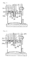
- a fourth preferred embodiment is illustrated in Fig. 4.
- a magnet 300a and a magnet 300c are disposed with their opposite magnetic poles opposed to each other, the magnet 300c is fitted and secured to the upper surface of the middle flange 351a of the gas pipe 351, and the magnet 300a is fixedly secured to the free end portion of the bend member 455 similarly to the third preferred embodiment.
- the middle flange 351a has been stopped to descend by the step portion 326a of the injection port 326, the upper surface of the middle flange 351a is biased downwards as the magnet 300c is attracted towards the magnet 300a.
- Fig. 6 is a perspective view of a gas pipe
- Fig. 7 is a cross-section view taken along line A-A in Fig. 5
- Fig. 8 is a cross-section view taken along line B-B in Fig. 5.
- a holding cylinder 504 On the outside of a housing 501 is slidably mounted a holding cylinder 504, which is formed in a hollow cylinder and serves to position and seal a container 534.
- the holding cylinder 504 is held in tight contact with an outer surface of the housing 501 at the location indicated by reference numeral 535, and at a central side surface portion it has a recess 536 engageable with a fork-shaped tool (not shown) for vertically moving this holding cylinder 504.
- the holding cylinder 504 has a positioning conical portion 537 formed in a tapered surface extending inwardly from its bottom end. At the inner end portion of this positioning conical portion 537 is disposed a sealing element 538 serving as a seal member for the container 534.
- the housing 501 has an inner piece 641 on its inside, and between the inner piece 641 and the housing 501 is formed a nearly annular liquid feed passageway 542. At the bottom of the liquid feed passageway 542 is provided an injection port 626, and a liquid jet flow is led to an inner wall surface of the container 534, where the liquid flows down towards the bottom while forming a laminar flow as much as possible.
- the housing 501 has a step 543 on its inside, and this simultaneously serves as an upper limit for the inner piece 641.
- a gas pipe 651 On the inside of the inner piece 641 is disposed a gas pipe 651, at the middle portion of the aforementioned gas pipe 651 is provided a gas pipe middle flange 651a, and this flange 651a has a gas pipe longer diameter flange portion 651c and a gas pipe shorter diameter flange portion 651d on opposed side surfaces which are orthogonal to each other.
- a step 626a having a slot-shaped opening which has a width narrower than the length of the gas pipe longer diameter flange 651c and broader than the length of the gas pipe shorter diameter flange 651c (See Fig. 7: It is to be noted that in Fig. 5, for convenience of explanation, the gas pipe longer diameter flange 651c and the step 626a are illustrated as directed in the same direction as the gas pipe lower flange 651b.). This step 626a serves to position the gas pipe 651 in the downward direction.
- a spring 672 Under the middle flange 651a of the gas pipe 651 and on the outsides of the gas pipe 651 is disposed a spring 672, its bottom end is fitted and secured to an upper surface of the gas pipe lower flange 651b, while its top end butts against a lower surface of a free end portion 756 of a bend member 755 fixedly secured to the holding cylinder 504, and thereby the gas pipe 651 is normally biased downwards with respect to the injection port 626 fixedly secured to the housing 501.
- the free end portion 756 of the bend member 755 slidably fits around the outer circumference of the gas pipe 651 under the middle flange, and the bend member 755 has the other arm 629 thereof connected to the holding cylinder 504 by means of a pin 525 and a nut 524.
- the gas pipe 651 is inhibited from rotation, hence the phase relationship between the gas pipe longer diameter flange 651c and the step 626a provided at the inner circumferential portion of the injection port is not variable and therefore, prevention of the gas pipe 651 from slipping out downwards can be insured.
- the gas pipe 651 in the case where the gas pipe 651 is to be replaced, if the holding cylinder 504 is extracted downwards, the fitting engagement between the gas pipe 651 and the free end portion 756 of the bend member 755 is released, therefore when the gas pipe 651 is rotated by 90°, as the position of the gas pipe longer diameter flange 651c comes to the position in the lengthwise direction of the slot-shaped opening formed at the step 626a provided at the inner circumferential portion of the injection port, the gas pipe 651 can be easily dismounted without using a tool.
- a spring for normally biasing a gas pipe downwards does not directly butt against a housing of a filling apparatus, also since when a container is taken out from a filling apparatus a stroke of raising a holding member upwards does not propagate to the above-mentioned spring, and further, since as a compression length of the spring only an adjustment width S (normally S being small as compared to a stroke of a holding member) for changing and adjusting a filled amount is necessary, there is no need to insure a space for mounting a spring within a filling nozzle as is the case with the apparatus in the prior art, and it becomes possible to employ the apparatus as a filling apparatus adapted for a container having a small mouth diameter which was difficult in the case of the apparatus in the prior art.
- the invention provides the advantage that accidents such as mixing of foreign matters into a container caused by breaking and dropping of a spring or a retainer ring due to an unexpectable trouble can be avoided.
- a liquid filling apparatus including a housing, an annular liquid feed passageway disposed within the housing, an annular liquid valve for opening and closing the liquid feed passageway, a holding member having a positioning conical portion and a sealing element for a container to be filled with liquid and disposed slidably along the housing, a gas pipe for introducing gas into the container and discharging gas from the same container, and a bend member fixedly secured to the holding member to hold the gas pipe in a vertically movable manner with respect to the holding member; the gas pipe slidably fits in an inner piece of the housing, a free end portion of the bend member fixedly secured to the holding member slidably fits between a middle flange and a lower flange provided on the gas pipe, a member for normally biasing the gas pipe downwardly is provided between a lower surface of the free end portion of the bend member and the lower flange of the gas pipe, the position in the downward direction of the gas pipe is limited by a
- the gas pipe upon replacement of a gas pipe, if the holding member is extracted downwards and the fitting engagement between the gas pipe and the bend member is released, then the gas pipe can be dismounted only by manually rotating the gas pipe by 90°.
Landscapes
- Filling Of Jars Or Cans And Processes For Cleaning And Sealing Jars (AREA)
Claims (3)
- Flüssigkeitsfüllvorrichtung zum Befüllen eines Behälters, umfassend ein Gehäuse, einen im Gehäuse angeordneten ringförmigen Flüssigkeitsspeisedurchgang, ein Flüssigkeitsventil zum Öffnen und Schließen des Flüssigkeitsspeisedurchgangs, ein einen konischen Positionierabschnitt und ein Dichtelement aufweisendes Halteelement (104) für einen mit Flüssigkeit zu befüllenden Behälter, welches Halteelement längs des Gehäuses verschiebbar angeordnet ist, und ein Gasrohr (151) zum Einführen von Gas in den Behälter und Abführen von Gas aus ihm, wobei das Gasrohr verschiebbar in ein Innenstück des Gehäuses eingesetzt ist und das Innenstück ein Element (170) zum Positionieren des Gasrohrs in der Abwärtsrichtung aufweist, dadurch gekennzeichnet, daß an der Innenumfangsseite des längs des Gehäuses verschiebbar angeordneten Halteelements ein längs der gleichen Innenumfangsfläche verschiebbar angeordneter kreisförmiger Ring (130) und eine Feder (172), um diesen Ring normalerweise in der Abwärtsrichtung vorzubelasten, angeordnet sind und ein gewünschter Spalt oder Zwischenraum zwischen einer Unterseite des kreisförmigen Rings und einer Oberseite eines konischen Positionierzylinders (137) mit einem Dicht(ungs)element für einen Mündungsrandteil eines mit Flüssigkeit zu befüllenden Behälters dadurch bereitgestellt ist, daß ein gebogenes Element oder Winkelelement (255), das um die Außenumfangsfläche des Gasrohrs herum aufgesetzt ist, am kreisförmigen Ring befestigt und der konische Positionierzylinder am Halteelement befestigt sind.
- Flüssigkeitsfüllvorrichtung, umfassend ein Gehäuse, einen im Gehäuse angeordneten ringförmigen Flüssigkeitsspeisedurchgng, ein ringförmiges Flüssigkeitsventil zum Öffnen und Schließen des Flüssigkeitsspeisedurchgangs, ein für einen mit Flüssigkeit zu befüllenden Behälter vorgesehenes und längs des Gehäuses verschiebbar angeordnetes Halteelement (304) mit einem konischen Positionierabschnitt (337) und einem Dicht(ungs)element, ein Gasrohr (351) zum Einführen von Gas in den Behälter und zum Abführen von Gas aus ihm sowie ein am Halteelement befestigtes gebogenes Element oder Winkelelement zum Halten des Gasrohrs in lotrecht bewegbarer Weise gegenüber dem Halteelement, dadurch gekennzeichnet, daß das Gasrohr verschiebbar in ein Innenstück (341) des Gehäuses eingesetzt ist, ein freier Endabschnitt des am Halteelement befestigten gebogenen Elements (455) verschiebbar zwischen einen mittleren Flansch (351a) und einen unteren Flansch (351b) am Gasrohr eingesetzt ist, ein das Gasrohr normalerweise nach unten vorbelastendes Element (372) zwischen einer Unterseite des freien Endabschnitts des gebogenen Elements und dem unteren Flansch des Gasrohrs vorgesehen ist, die Stellung des Gasrohrs in der Abwärtsrichtung durch eine am unteren Abschnitt des Gehäuse-Innenstücks vorgesehene Stufe (326a) und den mittleren Flansch des Gasrohrs begrenzt ist und damit ein vorbestimmter Spalt oder Zwischenraum zwischen dem mittleren Flansch des Gasrohrs und einer Oberseite des freien Endabschnitts des gebogenen Elements bereitgestellt ist.
- Flüssigkeitsfüllvorrichtung nach Anspruch 2, dadurch gekennzeichnet, daß der mittlere Flansch des Gasrohrs plattenförmig ausgebildet ist und einen größeren Durchmesser sowie einen kleineren Durchmesser in zwei zueinander orthogonalen Richtungen aufweist, die Stufe zum Abstützen des mittleren Flansches des Gasrohrs in bzw. als eine(r) schlitzförmige(n) Öffnung ausgebildet ist, deren Breite kleiner ist als der größere Durchmesser, aber größer als der kleinere Durchmesser, am unteren Ende des Gasrohrs eine Führungsfläche zur Anlage gegen das oder Eingriff mit dem gebogene(n) Element zwecks Verhinderung seiner Drehung angeformt ist und es dadurch ermöglicht ist, das Gasrohr durch Abziehen des des gebogenen Elements vom unteren Endabschnitt des Gasrohrs und Drehen des Gasrohrs um etwa 90° nach unten auszubauen (to dismount).
Applications Claiming Priority (6)
| Application Number | Priority Date | Filing Date | Title |
|---|---|---|---|
| JP4108090U JPH041198U (de) | 1990-04-19 | 1990-04-19 | |
| JP41080/90U | 1990-04-19 | ||
| JP4398890U JP2501328Y2 (ja) | 1990-04-26 | 1990-04-26 | 充填装置 |
| JP43988/90U | 1990-04-26 | ||
| JP49059/90U | 1990-05-14 | ||
| JP4905990U JP2503152Y2 (ja) | 1990-05-14 | 1990-05-14 | 充填装置 |
Publications (2)
| Publication Number | Publication Date |
|---|---|
| EP0452899A1 EP0452899A1 (de) | 1991-10-23 |
| EP0452899B1 true EP0452899B1 (de) | 1993-10-20 |
Family
ID=27290703
Family Applications (1)
| Application Number | Title | Priority Date | Filing Date |
|---|---|---|---|
| EP91106129A Expired - Lifetime EP0452899B1 (de) | 1990-04-19 | 1991-04-17 | Füllvorrichtung |
Country Status (3)
| Country | Link |
|---|---|
| US (1) | US5161585A (de) |
| EP (1) | EP0452899B1 (de) |
| DE (1) | DE69100519T2 (de) |
Families Citing this family (4)
| Publication number | Priority date | Publication date | Assignee | Title |
|---|---|---|---|---|
| DE4133713A1 (de) * | 1991-10-11 | 1993-04-15 | Kronseder Maschf Krones | Verfahren und vorrichtung zur fuellung eines gefaesses mit einer fluessigkeit |
| WO1994010079A1 (en) * | 1992-10-30 | 1994-05-11 | Simonazzi S.P.A. | A process for filling containers, in particular cans, with liquids, and a filler valve group for carrying out the process |
| DE102006051237B4 (de) * | 2006-10-31 | 2015-09-10 | Khs Gmbh | Spülgaseinbringung in Getränkedosen |
| US10464796B2 (en) * | 2016-05-03 | 2019-11-05 | Codi Manufacturing, Inc. | Modulated pressure control of beer fill flow |
Family Cites Families (7)
| Publication number | Priority date | Publication date | Assignee | Title |
|---|---|---|---|---|
| US2770263A (en) * | 1954-03-03 | 1956-11-13 | Crown Cork & Seal Co | Method and apparatus for filling containers with a liquid |
| US3889725A (en) * | 1970-08-29 | 1975-06-17 | Holstein & Kappert Maschf | Method of filling beer cans or the like |
| US4688608A (en) * | 1986-04-21 | 1987-08-25 | Figgie International, Inc. | Filling valves for cans and like containers |
| US4798234A (en) * | 1986-07-03 | 1989-01-17 | Adolph Coors Company | Can filling system |
| US4938261A (en) * | 1988-08-08 | 1990-07-03 | H & K Inc. | Apparatus for filling cans with a liquid |
| DE3836489A1 (de) * | 1988-10-26 | 1990-05-03 | Kronseder Maschf Krones | Verfahren und vorrichtung zum befuellen von getraenkedosen |
| JP2566311B2 (ja) * | 1989-03-09 | 1996-12-25 | 三菱重工業株式会社 | 充填装置 |
-
1991
- 1991-04-17 DE DE91106129T patent/DE69100519T2/de not_active Expired - Fee Related
- 1991-04-17 EP EP91106129A patent/EP0452899B1/de not_active Expired - Lifetime
- 1991-04-18 US US07/687,407 patent/US5161585A/en not_active Expired - Fee Related
Also Published As
| Publication number | Publication date |
|---|---|
| EP0452899A1 (de) | 1991-10-23 |
| US5161585A (en) | 1992-11-10 |
| DE69100519D1 (de) | 1993-11-25 |
| DE69100519T2 (de) | 1994-02-17 |
Similar Documents
| Publication | Publication Date | Title |
|---|---|---|
| US4410108A (en) | Pressure-actuated valve for use with positive displacement filling machine | |
| US3774658A (en) | Vent tube with slidable spreader for filling containers | |
| US3500879A (en) | Container filling apparatus | |
| EP1995208A1 (de) | Rotationsfüllmaschine zur Füllung von Behältern mit Flüssigkeiten | |
| US20020003005A1 (en) | Rugged high flow rate valve for bottle filling machines | |
| JPS62193992A (ja) | 背圧式の容器充填装置 | |
| NO940217L (no) | Fremgangsmåte for fylling av storsekker, og utstyr dertil | |
| US3299606A (en) | Automatic filling machine | |
| US3563287A (en) | Machines for filling beer kegs and like containers | |
| US4335761A (en) | Reciprocal bottle filling device | |
| EP0452899B1 (de) | Füllvorrichtung | |
| US4616684A (en) | Automatic bottling machine bottle holder | |
| AU2221092A (en) | Fill valve adapter and methods | |
| CA1172216A (en) | Automatic bottle filling device, and facility using same | |
| US4735238A (en) | Drum filling method and apparatus | |
| US4317475A (en) | Liquid filling and level sensing apparatus | |
| EP0488215B1 (de) | Vorrichtung zum Befüllen von Behältern | |
| US3152429A (en) | Apparatus for filling and sealing aerosol containers | |
| US3595280A (en) | Automatic filling valve | |
| EP0410332B1 (de) | Verfahren und Vorrichtung zur Beladung einer Flüssigkeit | |
| US4492259A (en) | Apparatus for filling bottles | |
| US5139056A (en) | Liquid charging method | |
| GB2172582A (en) | Tap for dispensing liquid from a tank | |
| US4771588A (en) | Machine for automatic sealing of sterile bottles in a bottle filling plant | |
| US2934238A (en) | Guide structure for bottle stoppering apparatus |
Legal Events
| Date | Code | Title | Description |
|---|---|---|---|
| PUAI | Public reference made under article 153(3) epc to a published international application that has entered the european phase |
Free format text: ORIGINAL CODE: 0009012 |
|
| 17P | Request for examination filed |
Effective date: 19910514 |
|
| AK | Designated contracting states |
Kind code of ref document: A1 Designated state(s): DE IT |
|
| 17Q | First examination report despatched |
Effective date: 19930318 |
|
| GRAA | (expected) grant |
Free format text: ORIGINAL CODE: 0009210 |
|
| AK | Designated contracting states |
Kind code of ref document: B1 Designated state(s): DE IT |
|
| REF | Corresponds to: |
Ref document number: 69100519 Country of ref document: DE Date of ref document: 19931125 |
|
| ITF | It: translation for a ep patent filed | ||
| PLBE | No opposition filed within time limit |
Free format text: ORIGINAL CODE: 0009261 |
|
| STAA | Information on the status of an ep patent application or granted ep patent |
Free format text: STATUS: NO OPPOSITION FILED WITHIN TIME LIMIT |
|
| 26N | No opposition filed | ||
| PGFP | Annual fee paid to national office [announced via postgrant information from national office to epo] |
Ref country code: DE Payment date: 20020424 Year of fee payment: 12 |
|
| PG25 | Lapsed in a contracting state [announced via postgrant information from national office to epo] |
Ref country code: DE Free format text: LAPSE BECAUSE OF NON-PAYMENT OF DUE FEES Effective date: 20031101 |
|
| PG25 | Lapsed in a contracting state [announced via postgrant information from national office to epo] |
Ref country code: IT Free format text: LAPSE BECAUSE OF NON-PAYMENT OF DUE FEES;WARNING: LAPSES OF ITALIAN PATENTS WITH EFFECTIVE DATE BEFORE 2007 MAY HAVE OCCURRED AT ANY TIME BEFORE 2007. THE CORRECT EFFECTIVE DATE MAY BE DIFFERENT FROM THE ONE RECORDED. Effective date: 20050417 |