EP0452930B1 - Dispositif pour l'ionisation et la spectrométrie de masse d'un échantillon - Google Patents
Dispositif pour l'ionisation et la spectrométrie de masse d'un échantillon Download PDFInfo
- Publication number
- EP0452930B1 EP0452930B1 EP91106232A EP91106232A EP0452930B1 EP 0452930 B1 EP0452930 B1 EP 0452930B1 EP 91106232 A EP91106232 A EP 91106232A EP 91106232 A EP91106232 A EP 91106232A EP 0452930 B1 EP0452930 B1 EP 0452930B1
- Authority
- EP
- European Patent Office
- Prior art keywords
- space
- fluid
- sample
- heat block
- introduction
- Prior art date
- Legal status (The legal status is an assumption and is not a legal conclusion. Google has not performed a legal analysis and makes no representation as to the accuracy of the status listed.)
- Expired - Lifetime
Links
- 238000004949 mass spectrometry Methods 0.000 title claims description 11
- 238000000050 ionisation spectroscopy Methods 0.000 title 1
- 239000012530 fluid Substances 0.000 claims description 104
- 150000002500 ions Chemical class 0.000 claims description 31
- 239000007788 liquid Substances 0.000 claims description 29
- 230000037361 pathway Effects 0.000 claims description 21
- 238000010438 heat treatment Methods 0.000 claims description 12
- 239000002904 solvent Substances 0.000 claims description 10
- 238000002347 injection Methods 0.000 claims description 8
- 239000007924 injection Substances 0.000 claims description 8
- 230000003247 decreasing effect Effects 0.000 claims description 7
- 239000012212 insulator Substances 0.000 claims description 5
- 230000001276 controlling effect Effects 0.000 claims description 2
- 230000001105 regulatory effect Effects 0.000 claims description 2
- 239000003595 mist Substances 0.000 description 28
- 238000002663 nebulization Methods 0.000 description 24
- 238000004807 desolvation Methods 0.000 description 20
- JUJWROOIHBZHMG-UHFFFAOYSA-N Pyridine Chemical compound C1=CC=NC=C1 JUJWROOIHBZHMG-UHFFFAOYSA-N 0.000 description 10
- UMJSCPRVCHMLSP-UHFFFAOYSA-N pyridine Natural products COC1=CC=CN=C1 UMJSCPRVCHMLSP-UHFFFAOYSA-N 0.000 description 5
- 230000008030 elimination Effects 0.000 description 4
- 238000003379 elimination reaction Methods 0.000 description 4
- 230000008901 benefit Effects 0.000 description 3
- 239000010419 fine particle Substances 0.000 description 3
- 238000004519 manufacturing process Methods 0.000 description 3
- 239000006199 nebulizer Substances 0.000 description 3
- 230000002093 peripheral effect Effects 0.000 description 3
- 238000005086 pumping Methods 0.000 description 3
- 230000035945 sensitivity Effects 0.000 description 3
- IJGRMHOSHXDMSA-UHFFFAOYSA-N Atomic nitrogen Chemical compound N#N IJGRMHOSHXDMSA-UHFFFAOYSA-N 0.000 description 2
- 238000006243 chemical reaction Methods 0.000 description 2
- 238000004891 communication Methods 0.000 description 2
- 230000006872 improvement Effects 0.000 description 2
- 239000002245 particle Substances 0.000 description 2
- 238000000926 separation method Methods 0.000 description 2
- XLYOFNOQVPJJNP-UHFFFAOYSA-N water Substances O XLYOFNOQVPJJNP-UHFFFAOYSA-N 0.000 description 2
- -1 and accordingly Substances 0.000 description 1
- 238000005515 capillary zone electrophoresis Methods 0.000 description 1
- 230000006866 deterioration Effects 0.000 description 1
- 230000002349 favourable effect Effects 0.000 description 1
- 239000007789 gas Substances 0.000 description 1
- 239000001307 helium Substances 0.000 description 1
- 229910052734 helium Inorganic materials 0.000 description 1
- SWQJXJOGLNCZEY-UHFFFAOYSA-N helium atom Chemical compound [He] SWQJXJOGLNCZEY-UHFFFAOYSA-N 0.000 description 1
- 238000001819 mass spectrum Methods 0.000 description 1
- 238000005259 measurement Methods 0.000 description 1
- 238000012986 modification Methods 0.000 description 1
- 230000004048 modification Effects 0.000 description 1
- 229910052757 nitrogen Inorganic materials 0.000 description 1
- 230000001737 promoting effect Effects 0.000 description 1
- 230000009467 reduction Effects 0.000 description 1
- 238000009834 vaporization Methods 0.000 description 1
- 230000008016 vaporization Effects 0.000 description 1
- 238000009423 ventilation Methods 0.000 description 1
Images


Classifications
-
- H—ELECTRICITY
- H01—ELECTRIC ELEMENTS
- H01J—ELECTRIC DISCHARGE TUBES OR DISCHARGE LAMPS
- H01J49/00—Particle spectrometers or separator tubes
- H01J49/02—Details
- H01J49/04—Arrangements for introducing or extracting samples to be analysed, e.g. vacuum locks; Arrangements for external adjustment of electron- or ion-optical components
- H01J49/0468—Arrangements for introducing or extracting samples to be analysed, e.g. vacuum locks; Arrangements for external adjustment of electron- or ion-optical components with means for heating or cooling the sample
- H01J49/049—Arrangements for introducing or extracting samples to be analysed, e.g. vacuum locks; Arrangements for external adjustment of electron- or ion-optical components with means for heating or cooling the sample with means for applying heat to desorb the sample; Evaporation
-
- H—ELECTRICITY
- H01—ELECTRIC ELEMENTS
- H01J—ELECTRIC DISCHARGE TUBES OR DISCHARGE LAMPS
- H01J49/00—Particle spectrometers or separator tubes
- H01J49/02—Details
- H01J49/04—Arrangements for introducing or extracting samples to be analysed, e.g. vacuum locks; Arrangements for external adjustment of electron- or ion-optical components
- H01J49/0431—Arrangements for introducing or extracting samples to be analysed, e.g. vacuum locks; Arrangements for external adjustment of electron- or ion-optical components for liquid samples
- H01J49/0445—Arrangements for introducing or extracting samples to be analysed, e.g. vacuum locks; Arrangements for external adjustment of electron- or ion-optical components for liquid samples with means for introducing as a spray, a jet or an aerosol
- H01J49/045—Arrangements for introducing or extracting samples to be analysed, e.g. vacuum locks; Arrangements for external adjustment of electron- or ion-optical components for liquid samples with means for introducing as a spray, a jet or an aerosol with means for using a nebulising gas, i.e. pneumatically assisted
-
- H—ELECTRICITY
- H01—ELECTRIC ELEMENTS
- H01J—ELECTRIC DISCHARGE TUBES OR DISCHARGE LAMPS
- H01J49/00—Particle spectrometers or separator tubes
- H01J49/02—Details
- H01J49/10—Ion sources; Ion guns
- H01J49/14—Ion sources; Ion guns using particle bombardment, e.g. ionisation chambers
- H01J49/145—Ion sources; Ion guns using particle bombardment, e.g. ionisation chambers using chemical ionisation
Definitions
- the present invention relates to a device which ionizes a sample for the purpose of, for example, mass spectrometry, and a mass spectrometer apparatus with this ionization device.
- a liquid chromatograph/mass spectrometer apparatus includes an ionization device serving as an interface between a liquid chromatograph and a mass analyzing unit. Liquid containing sample components and solvent is delivered from the liquid chromatograph into the ionization device where it is ionized for mass spectrometry. More specifically, the liquid from the liquid chromatograph is first introduced into a nebulizer of the ionization device and nebulized. The nebulized liquid is then delivered to a desolvation unit where the solvent molecules are separated from the sample molecules. The sample molecules are further transferred to a location as an ion source in which the sample molecules are ionized. Ions thus produced are delivered to the mass analyzing unit where they undergo mass separation and thereafter they are discharged out of the apparatus.
- nebulizers An example of commonly used or publicly known nebulizers is disclosed in Analytical Chemistry , 1988, vol. 60, pp. 774 - 780.
- This nebulizer includes a pipe having an inner diameter of 100 ⁇ m or so, and liquid from a liquid chromatograph is injected from the pipe and nebulized. The nebulized liquid is then introduced into a desolvation unit including a pipe whose inner diameter is about 5 mm.
- a space between the two pipes are open to the atmospheric pressure.
- the liquid is injected to this open space, causing friction between a flow of nebulized mist and the atmosphere. Due to this friction, the surrounding fluid is drawn into the nebulized mist flow, and actively collides with droplets of the nebulized mist, thus making the mist finer.
- the nebulization space is directly open to the atmosphere, and consequently, drawing of the fluid into the mist in the nebulization space is directly influenced by turbulence of the environment caused by ventilation of the apparatus, temperature difference and the like. Accordingly, stability in ionization of a sample is unfavorably affected, resulting in a problem of deterioration in accuracy of mass spectrometry.
- GB-A-2 151 021 Another example of a known nebuliser is disclosed in GB-A-2 151 021.
- the sample is injected into a low-pressure chamber which is evacuated by a pump.
- a fluid is introduced into the low-pressure chamber to envelope the nebulised sample as it flows through an outlet of the chamber so as to prevent the sample from contacting the chamber wall.
- An object of the present invention is to provide a device by which a sample can be ionized reliably by constantly producing a mist of fine particles.
- the ionization device of the invention has the advantage that it can constantly produce a mist of fine particles by preventing fluid supply to the mist from being directly influenced by turbulence of the environment surrounding the device.
- the liquid chromatograph/mass spectrometer apparatus of claim 27 has the advantage that a sample can be ionized reliably so as to obtain high accuracy in mass spectrometry.
- a space to which a sample is injected is enclosed and separated from surrounding fluid, and a fluid introduction pathway is formed to introduce the fluid into this space.
- a device for ionizing a sample comprises means for injecting and nebulizing the sample, means for defining a space to which the sample is injected, means for introducing fluid into the space; and means for ionizing the nebulized sample.
- the introduction means include at least one opening adjacent to the injection means so as to bring the fluid into contact with the injected sample and promote nebulization of the sample.
- the space defining means are shaped to surround the space and maintain a pressure-reduced condition of the space which is caused by contact between the injected sample and the fluid.
- the space in which the sample is nebulized is enclosed and separated from the environment.
- the fluid is introduced into the space through the introduction means, and drawn into the injected sample. Therefore, the introduced fluid in this space is less affected by turbulence of the environment than in a nebulization space of a conventional type which is completely open to the atmosphere. As a result, particles of the nebulized sample can be constantly made finer, and ionization can be accordingly performed reliably.
- the inner diameter of the space at a position where the sample is injected is preferably larger than that of an outlet through which the nebulized sample is delivered to the ionization means. More favorably, the inner diameter of the space is decreased gradually toward the outlet from the position where the sample is infected. For this reason, the space may be of a substantially conical shape which is suitable in respect of fluid resistance and production of the device.
- the fluid introduced into the space preferably, there are provided means for regulating an amount of the fluid and means for heating the fluid.
- the fluid introduction means are located in such a manner that the fluid is introduced in a direction inclined with respect to a flow of the injected sample.
- the fluid introduction means are located in such a manner that the fluid is introduced in a direction inclined with respect to a flow of the injected sample.
- an apparatus for mass spectrometry of a sample is constituted by combining the above-described ionization device with a liquid chromatograph and other means required for mass spectrometry.
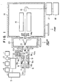
- a liquid chromatograph/mass spectrometer includes an eluant tank 1, a pump 2, a damper 3, a sample introduction port 4, and a column 5, and these system elements are successively connected by pipe lines so as to deliver liquid through them.
- the column 5 is connected in turn to an interface 6 of the liquid chromatograph/mass spectrometer having an ionization device according to one embodiment of a first aspect of the present invention.
- the liquid chromatograph/mass spectrometer shown in Fig. 1 is one embodiment according to a second aspect of the invention.
- the tank 1 contains eluant of mobile phase, and the eluant is supplied from the tank 1 by the pump 2.
- the flow of the eluant becomes stable in the damper 3 where pulsating flows of the eluant are extinguished.
- the sample introduction port 4 the eluant is supplied to the column 5.
- a sample is also introduced from the introduction port 4 to the column 5, and is separated into components in the column 5. Thereafter, the eluant is supplied to the interface 6.
- the interface 6 comprises a micropipe 6a, a desolvation unit 9, a corona discharger 10a, and a differential pumping unit 20.
- the micropipe 6a is extended through a heat block 8, and one end of the micropipe 6a is communicated with the column 5.
- the other end of the micropipe 6a is open toward a nebulization space or chamber 8a of the desolvation unit 9.
- a heater 7 is provided within the heat block 8 so as to heat the micropipe 6a.
- the eluant is nebulized from the tip of the micropipe 6a toward the nebulization space 8a.
- a mist thus produced is heated and vaporized in the desolvation unit 9 provided with a heater 9b, and is then transmitted to the corona discharger 10a.
- a high voltage is supplied from a power source 11 to a discharge needle 10 of the corona discharger 10a, and corona discharge is caused from the tip of the discharge needle 10.
- Solvent molecules of the liquid from the column 5 are first ionized by the corona discharge, and then, solute molecules, i.e., sample components of the liquid are ionized by ion/molecule reactions. After the ion/molecule reactions, the eluant required no longer is discharged from an opening 19 of the corona discharger 10a into the atmosphere by means of a fan.
- Ions thus produced are introduced into the differential pumping unit 20 through a first skimmer 12. At that time, the solvent molecules are separated and discharged out of the ionization device by a vacuum pump.
- the ions are further delivered to a mass analyzing unit 14 to which the differential pumping unit 20 is connected through a second skimmer 13.
- the ions enter a quadrupole 15 at a speed accelerated by an ion extracting electrode 14a so as to undergo mass separation and be determined by a detector 16.
- Output from the detector 16 is amplified by a direct current amplifier 17, and supplied to a data processor 18.
- the mass analyzing unit of the liquid chromatograph/mass spectrometer in this embodiment includes the quadrupole, the mass analyzing unit may be of a magnetic field type or the like.
- a member or block which defines the desolvation unit 9 is jointed with the heat block 8 through a thermal insulator 8b. Interposition of the thermal insulator 8b enables the micropipe 6a and the desolvation unit 9 to be heated up to their required respective temperatures.
- a plurality of fluid intake holes 9a are perforated through side walls of the desolvation unit 9 which define the nebulization space 8a. These fluid intake holes 9a are extended substantially perpendicular to the micropipe 6a and located radially at equal angular intervals around a flow of mist nebulized from the micropipe 6a, one end of each hole being open in the vicinity of the tip of the micropipe 6a. Fluid surrounding the interface 6 is drawn into the vicinity of the nebulized mist flow via the fluid intake holes 9a.
- the liquid from the column 5 is not vaporized within the micropipe 6a but nebulized all at once when it is discharged from the tip of the micropipe 6a into the nebulization space 8a.
- the nebulization space 8a is of a conical shape in symmetry to the axis of the nebulized mist flow. It should be noted that the nebulization space 8a is formed in such a manner that its inner diameter is decreased gradually in a range from the tip of the micropipe 6a to the outlet of the solvent elimination unit 9, i.e., the nebulization space 8a is reduced in diameter at the outlet.
- the nebulization space 8a In the nebulization space 8a, friction is caused between the nebulized mist flow from the micropipe 6a and the sucked fluid, and the fluid is drawn into the nebulized mist flow according to Bernoulii's theorem.
- the nebulization space 8a of the above-described shape serves to maintain the space at a pressure slightly lower than a pressure of the environment in order to ensure the supply of the fluid through the fluid intake holes 9a.
- collision of the nebulized mist with the drawn fluid is promoted so that droplets of the mist will be made finer.
- Such production of a fine mist leads to improvement of ionization efficiency and accordingly to improvement of sensitivity of mass spectrometry.
- these fine droplets pass through the desolvation unit 9, they are heated and made even finer.
- the nebulization space or chamber 8a is surrounded by the side walls of the desolvation unit 9, and it is not a space of a direct open type as in the conventional apparatus. Consequently, in comparison with a direct open type space, an intake of the fluid, i.e., an amount of supply of the fluid directed toward the nebulized mist flow is hardly affected by turbulence of the environment, thereby enabling reliable ionization.
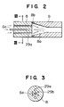
- Figs. 2 and 3 illustrate an essential portion of an ionization device according to a second embodiment of the invention.
- a pair of fluid introduction holes 29a and a plurality of heater elements 29b are extended through the heat block 8 substantially in parallel to the micropipe 6a.
- the fluid introduction holes 29a are located on both sides of the micropipe 6a, and the heater elements 29b are located between these fluid introduction hales 29a around the micropipe 6a.
- fluid supplied into the nebulization space or chamber 8a is heated when it flows through the introduction holes 29a within the heat block 8a.
- the heated fluid collides with mist particles from the micropipe 6a, thus promoting the vaporization of the droplets.
- the number of the fluid introduction holes 29a may be more than two so as to supply the fluid stably.
- Fig. 4 illustrates an essential portion of an ionization device according to a third embodiment of the invention.
- the heat block 8 and the desolvation unit 9 are slightly separated to have a gap 39a through which fluid is supplied toward a flow of nebulized mist.
- the heat block 8 and the solvent elimination unit 9 are joined by an adjusting member 39c which is extended over these two units so that they are not in direct contact but separated from each other.
- the adjusting member 39c is of a substantially hollow cylindrical shape, and the inner peripheries of both ends of the adjusting member 39c are screw-threaded.
- the outer periphery of the heat block 8 and the outer periphery of the desolvation unit 9 are similarly screw-threaded so that the adjusting member 39c is tightenedly screw-fitted to the heat block 8 at one end and to the desolvation unit 9 at the other end.
- the adjusting member 39c is screw-threaded in such a manner that it is screw-fitted to, one of the heat block 8 and the solvent elimination unit 9 in the left-hand screw direction and screw-fitted to the other in the right-hand screw direction.
- the heat block 8 and the desolvation unit 9 are separated from each other or moved closer to each other, thus controlling the gap 39a between these two units. Openings are formed in most of the outer peripheral portion of the adjusting member 39c so as not to obstruct the flowing course of the fluid.
- an essential portion of an ionization device is similar to the essential portion of the third embodiment.
- a heat block 48 and a desolvation unit 49 are slightly separated to have a gap 49a through which fluid is supplied in the same manner as the third embodiment.
- the gap 49a of this embodiment is of a conical ring-like shape.
- the end portion of the heat block 48 which faces the nebulization space 8a is conically shaped, and the associated end portion of the desolvation unit 49 is conically recessed at substantially the same angle.
- the heat block 48 and the desolvation unit 49 are jointed with each other by the adjusting member 39c in the same manner as the third embodiment, while defining the gap 49a of a conical ring-like shape between the complementarily shaped end portions of these two units.
- the gap 49c which is a fluid intake pathway is inclined with respect to a flow of nebulized mist, and accordingly, fluid can be introduced more stably. It is preferred that the fluid intake pathway is formed to supply the fluid toward the nebulized mist flow smoothly and stably and to heat the fluid for a sufficiently long period of time during the supply of the fluid.
- the size of the gap 39a or 49a for fluid introduction is an important factor for production of the mist having finer droplets and also for reliable ionization.
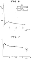
- Figs. 6 to 8 are graphs showing results of tests conducted by the inventors of the present application so as to investigate the influence of the size of the above-described gap.
- a liquid chromatograph/mass spectrometer including the ionization device shown in Fig. 5 was used to perform these tests.
- Fig. 6 illustrates a relationship between a distance D of the gap for fluid introduction and cluster ions detected with the mass spectrometer.
- a test was performed under the following measurement conditions: eluant of mobile phase was water 100%; the temperature of the heat block was 320°C; and the temperature of the desolvation unit was 400°C.
- Fig. 6 shows a relationship between an ion intensity ratio I 2 /I 1 of an intensity I 1 of ions of ⁇ H 3 O(H 2 O) ⁇ + and an intensity I 2 of ions of ⁇ H 3 O(H 2 O) 5 ⁇ + and the distance D.
- the intensity I 2 of ions of ⁇ H 3 O(H 2 O) 5 ⁇ + was higher than the intensity I 1 of ions of ⁇ H 3 O(H 2 O) ⁇ + .
- the ratio I 2 /I 1 was decreased drastically. After the distance D exceeded 2 mm, the ratio I 2 /I 1 was slightly increased, but after the distance D exceeded 10 mm, the ratio I 2 /I 1 was decreased again.
- Fig. 7 illustrates a relationship between an ion current of quasi-molecular ions (area value) and the distance D when 100 nanograms of pyridine was introduced under the same conditions as the test whose results are shown in Fig. 6.
- the ion-current of quasi-molecular ions was at its maximum when the distance D was 2 mm, and the sensitivity was decreased gradually as the distance D was increased.
- Ordinates of Fig. 7 indicate arbitrary units.
- Fig. 8 illustrates a relationship between an ion current (peak area) of pyridine quasi-molecular ions (m/z 80) and a flow rate of eluant of moving phase when the distance D was 2 mm and 20 mm.
- the temperature of the heat block was set to such a value that the ion current would be at its maximum when the flow rate was 1 ml/min, and the temperature was maintained at this value throughout the test. Results of the test are plotted in Fig. 8 with the ion current of pyridine quasi-molecular ions when the flow rate was 1 ml/min being 100.
- the ion current is low at the distance D in a range from 0 when the heat block and the solvent elimination unit are closely fitted to each other to 1 mm because the mist cannot have fine particles due to negative pressure in the nebulization chamber to thereby increase the size of cluster ions. Therefore, the sensitivity of pyridine becomes insufficient.
- the distance D is increased, the fluid is adequately supplied, and droplets of the mist can be made finer, thus lessening the size of cluster ions.
- the amount of the supplied fluid is large, and the temperature of the supplied fluid is relatively low, thereby setting a limit to promotion of fineness of the mist.
- Fig. 9 illustrates an essential portion of an ionization device according to a fifth embodiment of the present invention.
- the above-described first to fourth embodiments are of a natural supply type in which the pressure reduction phenomenon induced by the nebulized mist flowing through the nebulization chamber is utilized for supplying the surrounding fluid.
- fluid is controlled to be forcibly supplied. More specifically, a fluid pathway 59e of such an annular shape as to surround the nebulization chamber 8a is formed within the side walls of the desolvation unit 9, and a fluid inlet 59d in communication with the pathway 59e is formed in an outer peripheral portion of the desolvation unit 9.
- a plurality of fluid outlets 59f are dispersedly formed in an inner peripheral portion of the nebulization chamber 8a.
- the outlets 59f are in communication with the pathway 59e and open toward the nebulization chamber 8a in the vicinity of the tip of the micropipe 6a.
- a fluid reservoir 51 in which fluid such as nitrogen and helium is stored at a pressure more than one atmospheric pressure.
- the fluid reservoir 51 is connected to the fluid inlet 59d from which the fluid is forcibly supplied through the pathway 59e and the outlets 59f into the nebulization chamber 8a.
- reference numeral 52 denotes a heater which heats the fluid reservoir 51.
- the fluid When the fluid is stored in the reservoir 51 at one atmospheric pressure, the fluid is fed from the reservoir 51 to the nebulization chamber 8a in accordance with a pressure-reduced condition of the nebulization chamber 8a in the same manner as the natural supply type embodiments described previously.
- the ionization device is applied to the liquid chromatograph/mass spectrometer in the above description.
- it can be used in an SFC/MS (supercritical fluid chromatograph/mass spectrometer) and a capillary zone electrophoresis/mass spectrometer, and it can be also used as a detector for a liquid chromatograph.
Landscapes
- Chemical & Material Sciences (AREA)
- Analytical Chemistry (AREA)
- Physics & Mathematics (AREA)
- Engineering & Computer Science (AREA)
- Plasma & Fusion (AREA)
- Dispersion Chemistry (AREA)
- Other Investigation Or Analysis Of Materials By Electrical Means (AREA)
- Electron Sources, Ion Sources (AREA)
- Electron Tubes For Measurement (AREA)
Claims (27)
- Appareil pour ioniser un échantillon, comportant :des moyens (6, 6a, 8, 48) pour injecter et nébuliser l'échantillon,des moyens (9, 49) définissant un espace (8a) dans lequel est injecté l'échantillon,des moyens (9a, 29a, 39a, 49a, 59d à 59f), comportant une ouverture, pour introduire un fluide dans ledit espace, etdes moyens (10) pour ioniser l'échantillon nébulisé,caractérisé en ce queladite ouverture est agencée adjacente auxdits moyens d'injection pour laisser l'échantillon injecté entrer en collision avec le fluide introduit pour favoriser la nébulisation de l'échantillon et entraîner une pression réduite dans ledit espace par laquelle ledit fluide est entraîné dans lequel, lesdits moyens définissant un espace entourent ledit espace de sorte que la pression réduite est maintenue dans celui-ci.
- Appareil selon la revendication 1, comportant en outre des moyens (39c) pour réguler la quantité de fluide introduit dans ledit espace (8a). (Figure 4, figure 5).
- Appareil selon la revendication 2, dans lequel lesdits moyens de régulation (39c) règlent la quantité de fluide introduit dans ledit espace (8a) en commandant les dimensions de l'ouverture desdits moyens d'introduction (39a, 49a).
- Appareil selon la revendication 1, comportant en outre des moyens (29b, 52) pour chauffer le fluide introduit dans ledit espace. (Figure 4, figure 9).
- Appareil selon la revendication 4, dans lequel lesdits moyens de chauffage (29b) sont situés adjacents auxdits moyens d'introduction (29a) de manière à chauffer le fluide s'écoulant à travers lesdits moyens d'introduction (29a).
- Appareil selon la revendication 1, dans lequel le fluide est entraîné dans ledit espace (8a) à partir de l'extérieur du fait de l'état sous pression réduite dudit espace (8a).
- Appareil selon la revendication 1, comportant en outre des moyens (51) pour stocker le fluide sous pression, lesdits moyens de stockage (51) étant reliés auxdits moyens d'introduction (59d à 59f) de manière à alimenter le fluide jusqu'à l'intérieur dudit espace (8a).(Figure 9)
- Appareil selon la revendication 7, comportant en outre des moyens (52) pour chauffer le fluide introduit dans ledit espace, lesdits moyens de chauffage (52) étant combinés avec lesdits moyens de stockage (51) de manière à chauffer le fluide situé à l'intérieur desdits moyens de stockage (51).
- Appareil selon la revendication 1, dans lequel lesdits moyens d'introduction comportent plusieurs trajets d'introduction de fluide (9a) s'étendant sensiblement perpendiculairement à un écoulement de l'échantillon injecté, chacun desdits trajets d'introduction de fluide (9a) étant ouvert vers l'extérieur dudit espace (8a) de manière à introduire le fluide extérieur jusqu'à l'intérieur dudit espace (8a) . (Figure 1).
- Appareil selon la revendication 9, dans lequel lesdits trajets d'introduction de fluide (9a) sont situés radialement à intervalles angulaires sensiblement égaux autour de l'écoulement de l'échantillon injecté.
- Appareil selon la revendication 1, dans lequel lesdits moyens d'injection (6a, 8) comportent une microtuyauterie (6a) pour alimenter l'échantillon, qui est ouverte dans ledit espace (8a), lesdits moyens d'introduction (8, 29a) comportant plusieurs trajets d'introduction de fluide (29a) adjacents à ladite microtuyauterie et sensiblement parallèles à ladite microtuyauterie (6a), chacun desdits trajets d'introduction de fluide (29a) étant ouvert vers l'extérieur dudit espace (8a) de manière à introduire le fluide extérieur jusqu'à l'intérieur dudit espace (8a). (Figure 2).
- Appareil selon la revendication 11, dans lequel lesdits moyens d'introduction (8, 29a) comportent deux parmi lesdits trajets d'introduction de fluide (29a), qui sont situés sur les deux côtés de ladite microtuyauterie (6a).
- Appareil selon la revendication 11, comportant en outre des moyens (29b) pour chauffer le fluide introduit dans ledit espace (8a), lesdits moyens de chauffage (29b) étant situés entre lesdits trajets d'introduction de fluide (29a) de manière à entourer ladite microtuyauterie (6a).
- Appareil selon la revendication 1, dans lequel lesdits moyens d'introduction (6a, 48) sont situés d'une manière telle que le fluide est introduit dans une direction inclinée par rapport à l'écoulement de l'échantillon injecté. (Figure 5).
- Appareil selon la revendication 1, dans lequel ledit espace (8a) comporte une sortie à travers laquelle l'échantillon nébulisé est transféré vers lesdits moyens d'ionisation (10), le diamètre intérieur dudit espace (8a) au niveau d'une position où l'échantillon est injecté étant plus grand que celui de ladite sortie.
- Appareil selon la revendication 15, dans lequel le diamètre intérieur dudit espace (8a) diminue graduellement en direction de ladite sortie à partir de la position où l'échantillon est injecté.
- Appareil selon la revendication 1, dans lequel lesdits moyens d'injection (6a, 8, 48) comportent un bloc de chauffage (8, 48) ayant un trajet (6a) pour alimenter l'échantillon et un dispositif de chauffage (7) pour chauffer l'échantillon, lesdits moyens définissant un espace comportant un élément (9, 49) qui enferme le espace (8a) de manière à séparer ledit espace (8a) du fluide entourant, ledit espace (8a) étant défini par ledit élément (9, 49) en liaison avec ledit bloc de chauffage (8, 48).
- Appareil selon la revendication 17, dans lequel ledit bloc de chauffage (8) et ledit élément (9) sont reliés de manière fixe par l'intermédiaire d'un isolant thermique (8b) interposé entre ceux-ci.
- Appareil selon la revendication 17, dans lequel ledit bloc de chauffage (8, 48) et ledit élément (9, 49) sont séparés pour avoir un écartement (39, 49a) entre eux, lesdits moyens d'introduction étant constitués de l'écartement (39a, 49a) existant entre ledit bloc de chauffage (8, 48) et ledit élément (9, 49).
- Appareil selon la revendication 17, dans lequel la partie d'extrémité dudit bloc de chauffage (48) qui fait face audit élément (49), a une forme sensiblement conique, la partie d'extrémité dudit élément (49) qui fait face audit bloc de chauffage (48) étant creusée de manière conique correspondante, ledit écartement (49a) ayant une forme analogue à un anneau conique incliné par rapport à l'écoulement de l'échantillon injecté.
- Appareil selon la revendication 19 ou 20, comportant en outre des moyens (39c) pour régler ledit écartement (49a) existant entre ledit bloc de chauffage (48) et ledit élément (49).
- Appareil selon la revendication 1 ou 21, dans lequel ledit espace (8a) a une forme sensiblement conique.
- Appareil selon la revendication 1, dans lequel lesdits moyens d'injection (6a, 8) comportent un bloc de chauffage (8), une microtuyauterie (6a) pour alimenter l'échantillon, qui s'étend à travers ledit bloc de chauffage (8), et un dispositif de chauffage (7) pour chauffer l'échantillon, lesdits moyens définissant un espace comportant un élément (9) qui enferme ledit espace (8a) de manière à séparer ledit espace (8a) du fluide entourant, ledit élément (9) et ledit bloc de chauffage étant reliés de manière fixe par l'intermédiaire d'un isolant thermique (8b) interposé entre eux de manière à définir l'espace (8a) ayant une forme à peu près conique, lesdits moyens d'introduction comportant plusieurs trajets d'introduction de fluide (9a) qui s'étendent à travers ledit élément (9), lesdits trajets d'introduction de fluide (9a) étant situés radialement à intervalles angulaires sensiblement égaux autour d'un écoulement de l'échantillon injecté, tout en s'étendant sensiblement perpendiculairement à l'écoulement de l'échantillon injecté, chacun desdits trajets d'introduction de fluide (9a) étant ouvert vers l'extérieur dudit espace (8a) de manière à introduire le fluide extérieur jusqu'à l'intérieur dudit espace (8a). (Figure 1).
- Appareil selon la revendication 1, dans lequel lesdits moyens d'injection (6a, 8) comportent un bloc de chauffage (8), une microtuyauterie (6a) pour alimenter l'échantillon, qui s'étend à travers ledit bloc de chauffage (8), et un dispositif de chauffage (29b) pour chauffer l'échantillon, lesdits moyens définissant un espace comportant un élément (9) qui enferme ledit espace (8a) de manière à séparer ledit espace (8a) du fluide entourant, ledit élément (9) et ledit bloc de chauffage (8) étant reliés de manière fixe par l'intermédiaire d'un isolant thermique (8b) interposé entre eux de manière à définir l'espace (8a) ayant une forme sensiblement conique, lesdits moyens d'introduction comportant deux des trajets d'introduction de fluide (29a) qui s'étendent à travers ledit bloc de chauffage (8) à peu près parallèlement à ladite microtuyauterie, ledit dispositif de chauffage (29b) servant aussi à chauffer le fluide s'écoulant à travers lesdits trajets d'introduction de fluide (29a). (Figure 2).
- Appareil selon la revendication 1, dans lequel lesdits moyens d'injection (6a, 8, 48) comportent un bloc de chauffage (8, 48), une microtuyauterie (6a) pour alimenter l'échantillon, qui s'étend à travers ledit bloc de chauffage (8, 48), et un dispositif de chauffage (7) pour chauffer l'échantillon, lesdits moyens définissant un espace comportant un élément (9, 49) qui enferme ledit espace (8a) de manière à séparer ledit espace (8a) du fluide entourant, ledit élément (9, 49) en liaison avec ledit bloc de chauffage (8, 48) définissant ledit espace (8a) ayant une forme sensiblement conique, ledit bloc de chauffage (8, 48) et ledit élément (9, 49) étant mobiles l'un par rapport à l'autre pour avoir un écartement variable (39a, 49a) entre eux, lesdits moyens d'introduction étant l'écartement (39a, 49a) existant entre ledit bloc de chauffage (8, 48) et ledit élément (9, 49). (Figure 4, figure 5).
- Appareil selon la revendication 1, dans lequel lesdits moyens d'injection (6a, 48) comportent un bloc de chauffage (48), une microtuyauterie (6a) pour alimenter l'échantillon, qui s'étend à travers ledit bloc de chauffage (48), et un dispositif de chauffage (7) pour chauffer l'échantillon, lesdits moyens définissant un espace comportant un élément (49) qui enferme ledit espace (8a) de manière à séparer ledit espace (8a) du fluide entourant, ledit élément (49) en liaison avec ledit bloc de chauffage (48) définissant ledit espace (8a) ayant une forme sensiblement conique, ledit bloc de chauffage (48) et ledit élément (49) étant mobiles l'un par rapport à l'autre pour avoir un écartement variable (49a) entre eux, la partie d'extrémité dudit bloc de chauffage (48) qui fait face audit élément (49) ayant une forme sensiblement conique, la partie d'extrémité dudit élément (49) qui fait face audit bloc de chauffage (48) étant creusée de manière conique correspondante, ledit écartement (49a) ayant une forme analogue à un anneau conique incliné par rapport à un écoulement de l'échantillon injecté, lesdits moyens d'introduction étant l'écartement (49a) existant entre ledit bloc de chauffage (48) et ledit élément (49).
- Appareil pour spectrométrie de masse des composants d'un échantillon, comportant un appareil selon l'une quelconque des revendications 1 à 26 etun chromatographe liquide (1 à 5) alimentant un liquide comportant lesdits composants d'échantillon et un solvant en tant que dit échantillon pour ledit appareil d'ionisation,des moyens (19) pour séparer et enlever les molécules de solvant des molécules des composants d'échantillon et pour alimenter les composants d'échantillon vers lesdits moyens d'ionisation (10),des moyens (14) pour spectrométrie de masse des ions produits par les moyens d'ionisation, etdes moyens (16) pour détecter les ions soumis à la spectrométrie de masse.
Applications Claiming Priority (2)
| Application Number | Priority Date | Filing Date | Title |
|---|---|---|---|
| JP2100323A JP2633974B2 (ja) | 1990-04-18 | 1990-04-18 | 試料のイオン化および質量分析のための装置 |
| JP100323/90 | 1990-04-18 |
Publications (3)
| Publication Number | Publication Date |
|---|---|
| EP0452930A2 EP0452930A2 (fr) | 1991-10-23 |
| EP0452930A3 EP0452930A3 (en) | 1991-12-18 |
| EP0452930B1 true EP0452930B1 (fr) | 1996-07-03 |
Family
ID=14270970
Family Applications (1)
| Application Number | Title | Priority Date | Filing Date |
|---|---|---|---|
| EP91106232A Expired - Lifetime EP0452930B1 (fr) | 1990-04-18 | 1991-04-18 | Dispositif pour l'ionisation et la spectrométrie de masse d'un échantillon |
Country Status (4)
| Country | Link |
|---|---|
| US (1) | US5170052A (fr) |
| EP (1) | EP0452930B1 (fr) |
| JP (1) | JP2633974B2 (fr) |
| DE (1) | DE69120583T2 (fr) |
Families Citing this family (32)
| Publication number | Priority date | Publication date | Assignee | Title |
|---|---|---|---|---|
| JP2505060Y2 (ja) * | 1990-08-30 | 1996-07-24 | 日新電機株式会社 | イオン源 |
| US5526682A (en) * | 1991-05-02 | 1996-06-18 | Waters Investments Limited | Method and apparatus for analyzing sample solutions |
| JP2902197B2 (ja) * | 1992-02-04 | 1999-06-07 | 株式会社日立製作所 | 大気圧イオン化質量分析装置 |
| CA2062629C (fr) * | 1992-03-10 | 1999-06-15 | John Barry French | Appareil et methode d'introduction d'echantillon liquide |
| US5304798A (en) * | 1992-04-10 | 1994-04-19 | Millipore Corporation | Housing for converting an electrospray to an ion stream |
| JP3172283B2 (ja) * | 1992-10-20 | 2001-06-04 | 株式会社日立製作所 | 質量分析用試料のイオン化装置 |
| JPH06310091A (ja) * | 1993-04-26 | 1994-11-04 | Hitachi Ltd | 大気圧イオン化質量分析計 |
| JP2568158Y2 (ja) * | 1993-07-16 | 1998-04-08 | 日本電子株式会社 | ネブライザー |
| JP3087548B2 (ja) * | 1993-12-09 | 2000-09-11 | 株式会社日立製作所 | 液体クロマトグラフ結合型質量分析装置 |
| US6147347A (en) * | 1994-03-15 | 2000-11-14 | Hitachi, Ltd. | Ion source and mass spectrometer instrument using the same |
| DE4415480C2 (de) * | 1994-05-02 | 1999-09-02 | Bruker Daltonik Gmbh | Vorrichtung und Verfahren zur massenspektrometrischen Untersuchung von Substanzgemischen durch Kopplung kapillarelektrophoretischer Separation (CE) mit Elektrospray-Ionisierung (ESI) |
| JP3415682B2 (ja) | 1994-08-10 | 2003-06-09 | 株式会社日立製作所 | キャピラリー電気泳動・質量分析計 |
| JP3274302B2 (ja) * | 1994-11-28 | 2002-04-15 | 株式会社日立製作所 | 質量分析計 |
| JP3353561B2 (ja) * | 1995-09-07 | 2002-12-03 | 株式会社日立製作所 | 溶液の質量分析に関する方法と装置 |
| US5969351A (en) * | 1996-02-07 | 1999-10-19 | Hitachi, Ltd. | Mass spectrometer |
| JP3494553B2 (ja) * | 1996-08-30 | 2004-02-09 | 株式会社日立製作所 | 質量分析装置 |
| US5969352A (en) * | 1997-01-03 | 1999-10-19 | Mds Inc. | Spray chamber with dryer |
| DE10155775B4 (de) * | 2001-11-14 | 2006-04-06 | CARBOTEC Gesellschaft für instrumentelle Analytik mbH | Fokussierte Elektrosprayvorrichtung |
| US6818888B2 (en) * | 2002-04-04 | 2004-11-16 | Varian, Inc. | Vortex flow atmospheric pressure chemical ionization source for mass spectrometry |
| US7015466B2 (en) | 2003-07-24 | 2006-03-21 | Purdue Research Foundation | Electrosonic spray ionization method and device for the atmospheric ionization of molecules |
| FI119747B (fi) * | 2003-11-14 | 2009-02-27 | Licentia Oy | Menetelmä ja laitteisto näytteiden tutkimiseksi massaspektrometrisesti |
| JP2010512514A (ja) * | 2006-12-06 | 2010-04-22 | ザ・キュレイターズ・オブ・ザ・ユニバーシティ・オブ・ミズーリ | 液体クロマトグラフィー検出器およびそのためのフローコントローラ |
| WO2009152321A1 (fr) * | 2008-06-11 | 2009-12-17 | The Curators Of The University Of Missouri | Détecteur de chromatographie en phase liquide et régulateur de débit pour ledit détecteur |
| DE102009045116A1 (de) * | 2009-09-29 | 2011-03-31 | Evonik Degussa Gmbh | Niederdruckvermahlungsverfahren |
| GB201109384D0 (en) * | 2011-06-03 | 2011-07-20 | Micromass Ltd | Sampling with increased efficiency |
| JP2013007639A (ja) * | 2011-06-24 | 2013-01-10 | Hitachi High-Technologies Corp | 液体クロマトグラフ質量分析装置 |
| CA2852043C (fr) * | 2011-10-26 | 2020-08-25 | Fluidigm Canada Inc. | Appareil de transfert d'echantillon pour cytometrie de masse |
| EP3047507B1 (fr) * | 2013-09-20 | 2019-06-26 | Micromass UK Limited | Interface pour source d'ions et boîtier sous vide |
| WO2015110860A1 (fr) * | 2014-01-24 | 2015-07-30 | Dh Technologies Development Pte. Ltd. | Systèmes et procédés pour distribuer un liquide à une source d'ions |
| EP3240014A1 (fr) * | 2016-04-29 | 2017-11-01 | ETH Zurich | Cellule d'ablation laser |
| US10147592B2 (en) * | 2016-05-18 | 2018-12-04 | Perkinelmer Health Sciences Canada, Inc. | Spray chambers and methods of using them |
| JP7327130B2 (ja) * | 2019-12-05 | 2023-08-16 | 株式会社島津製作所 | イオン分析装置 |
Family Cites Families (9)
| Publication number | Priority date | Publication date | Assignee | Title |
|---|---|---|---|---|
| JPS4722976U (fr) * | 1971-03-25 | 1972-11-15 | ||
| JPH065228B2 (ja) * | 1983-12-13 | 1994-01-19 | 株式会社日立製作所 | 大気圧イオン化式試料導入装置 |
| JPS60129668A (ja) * | 1983-12-19 | 1985-07-10 | Jeol Ltd | 液体クロマトグラフ質量分析装置 |
| JPH01146262A (ja) * | 1987-12-03 | 1989-06-08 | Toshiba Corp | 燃料電池 |
| US4977785A (en) * | 1988-02-19 | 1990-12-18 | Extrel Corporation | Method and apparatus for introduction of fluid streams into mass spectrometers and other gas phase detectors |
| JPH0627726B2 (ja) * | 1988-04-22 | 1994-04-13 | 株式会社日立製作所 | 質量分析計 |
| JP2834136B2 (ja) * | 1988-04-27 | 1998-12-09 | 株式会社日立製作所 | 質量分析計 |
| JPH0713624B2 (ja) * | 1988-10-05 | 1995-02-15 | 株式会社日立製作所 | イオンの抽出および分析装置 |
| US4996424A (en) * | 1990-05-03 | 1991-02-26 | Hitachi, Ltd. | Atmospheric pressure ionization mass spectrometer |
-
1990
- 1990-04-18 JP JP2100323A patent/JP2633974B2/ja not_active Expired - Fee Related
-
1991
- 1991-04-17 US US07/686,361 patent/US5170052A/en not_active Expired - Lifetime
- 1991-04-18 EP EP91106232A patent/EP0452930B1/fr not_active Expired - Lifetime
- 1991-04-18 DE DE69120583T patent/DE69120583T2/de not_active Expired - Fee Related
Also Published As
| Publication number | Publication date |
|---|---|
| DE69120583D1 (de) | 1996-08-08 |
| JP2633974B2 (ja) | 1997-07-23 |
| US5170052A (en) | 1992-12-08 |
| DE69120583T2 (de) | 1997-02-13 |
| EP0452930A3 (en) | 1991-12-18 |
| JPH042033A (ja) | 1992-01-07 |
| EP0452930A2 (fr) | 1991-10-23 |
Similar Documents
| Publication | Publication Date | Title |
|---|---|---|
| EP0452930B1 (fr) | Dispositif pour l'ionisation et la spectrométrie de masse d'un échantillon | |
| US6278111B1 (en) | Electrospray for chemical analysis | |
| JP4178110B2 (ja) | 質量分析装置 | |
| US4531056A (en) | Method and apparatus for the mass spectrometric analysis of solutions | |
| US5898175A (en) | Mass spectrometer and mass spectrometry method for analyzing compounds contained in a solution | |
| US9870904B2 (en) | Ion source for mass spectrometry | |
| US4999493A (en) | Electrospray ionization interface and method for mass spectrometry | |
| US10818486B2 (en) | System for minimizing electrical discharge during ESI operation | |
| US20060145071A1 (en) | Apparatus for delivering ions from a grounded electrospray assembly to a vacuum chamber | |
| JP5589750B2 (ja) | 質量分析装置用イオン化装置及び該イオン化装置を備える質量分析装置 | |
| US5162651A (en) | Mass spectrometer | |
| EP0888169A1 (fr) | Enceinte de repartition d'echantillons, subatmospherique et a pression variable, aux fins d'une ionisation par electro-pulverisation/spectrometrie de masse et d'autres applications | |
| GB2441601A (en) | Ionizing apparatus | |
| JP4454157B2 (ja) | 質量分析装置のためのイオン源 | |
| CN112106170A (zh) | 撞击电离喷雾离子源或电喷雾电离离子源 | |
| US6646255B2 (en) | Liquid chromatograph/mass spectrometer and its ionization interface | |
| US11189477B2 (en) | APCI ion source with asymmetrical spray | |
| WO2019053851A1 (fr) | Pulvérisateur esi et dispositif d'ionisation | |
| US11222778B2 (en) | Multi-electrospray ion source for a mass spectrometer | |
| US20030062474A1 (en) | Electrospray ion source for mass spectrometry with atmospheric pressure desolvating capabilities | |
| JP7433477B2 (ja) | イオン源およびこれを備えた質量分析計 | |
| JP2002015697A (ja) | エレクトロスプレー・イオン源 | |
| JP3948096B2 (ja) | Lc/msインタフェース | |
| JPH09119915A (ja) | 試料のイオン化および質量分析のための装置 | |
| WO2000019193A1 (fr) | Dispositif d'electronebulisation a courant divergent pour spectrometrie de masse |
Legal Events
| Date | Code | Title | Description |
|---|---|---|---|
| PUAI | Public reference made under article 153(3) epc to a published international application that has entered the european phase |
Free format text: ORIGINAL CODE: 0009012 |
|
| AK | Designated contracting states |
Kind code of ref document: A2 Designated state(s): DE FR GB |
|
| PUAL | Search report despatched |
Free format text: ORIGINAL CODE: 0009013 |
|
| AK | Designated contracting states |
Kind code of ref document: A3 Designated state(s): DE FR GB |
|
| 17P | Request for examination filed |
Effective date: 19920525 |
|
| 17Q | First examination report despatched |
Effective date: 19940919 |
|
| GRAH | Despatch of communication of intention to grant a patent |
Free format text: ORIGINAL CODE: EPIDOS IGRA |
|
| GRAA | (expected) grant |
Free format text: ORIGINAL CODE: 0009210 |
|
| AK | Designated contracting states |
Kind code of ref document: B1 Designated state(s): DE FR GB |
|
| REF | Corresponds to: |
Ref document number: 69120583 Country of ref document: DE Date of ref document: 19960808 |
|
| ET | Fr: translation filed | ||
| PLBE | No opposition filed within time limit |
Free format text: ORIGINAL CODE: 0009261 |
|
| STAA | Information on the status of an ep patent application or granted ep patent |
Free format text: STATUS: NO OPPOSITION FILED WITHIN TIME LIMIT |
|
| 26N | No opposition filed | ||
| REG | Reference to a national code |
Ref country code: GB Ref legal event code: IF02 |
|
| PGFP | Annual fee paid to national office [announced via postgrant information from national office to epo] |
Ref country code: GB Payment date: 20060424 Year of fee payment: 16 Ref country code: FR Payment date: 20060424 Year of fee payment: 16 |
|
| PGFP | Annual fee paid to national office [announced via postgrant information from national office to epo] |
Ref country code: DE Payment date: 20060602 Year of fee payment: 16 |
|
| GBPC | Gb: european patent ceased through non-payment of renewal fee |
Effective date: 20070418 |
|
| PG25 | Lapsed in a contracting state [announced via postgrant information from national office to epo] |
Ref country code: DE Free format text: LAPSE BECAUSE OF NON-PAYMENT OF DUE FEES Effective date: 20071101 |
|
| PG25 | Lapsed in a contracting state [announced via postgrant information from national office to epo] |
Ref country code: GB Free format text: LAPSE BECAUSE OF NON-PAYMENT OF DUE FEES Effective date: 20070418 |
|
| PG25 | Lapsed in a contracting state [announced via postgrant information from national office to epo] |
Ref country code: FR Free format text: LAPSE BECAUSE OF NON-PAYMENT OF DUE FEES Effective date: 20070430 |