EP0453182A1 - Metallrohrherstellung - Google Patents
Metallrohrherstellung Download PDFInfo
- Publication number
- EP0453182A1 EP0453182A1 EP91303203A EP91303203A EP0453182A1 EP 0453182 A1 EP0453182 A1 EP 0453182A1 EP 91303203 A EP91303203 A EP 91303203A EP 91303203 A EP91303203 A EP 91303203A EP 0453182 A1 EP0453182 A1 EP 0453182A1
- Authority
- EP
- European Patent Office
- Prior art keywords
- metal strip
- brazing wire
- tube
- edge portion
- forming
- Prior art date
- Legal status (The legal status is an assumption and is not a legal conclusion. Google has not performed a legal analysis and makes no representation as to the accuracy of the status listed.)
- Granted
Links
Images


Classifications
-
- B—PERFORMING OPERATIONS; TRANSPORTING
- B21—MECHANICAL METAL-WORKING WITHOUT ESSENTIALLY REMOVING MATERIAL; PUNCHING METAL
- B21C—MANUFACTURE OF METAL SHEETS, WIRE, RODS, TUBES, PROFILES OR LIKE SEMI-MANUFACTURED PRODUCTS OTHERWISE THAN BY ROLLING; AUXILIARY OPERATIONS USED IN CONNECTION WITH METAL-WORKING WITHOUT ESSENTIALLY REMOVING MATERIAL
- B21C37/00—Manufacture of metal sheets, rods, wire, tubes, profiles or like semi-manufactured products, not otherwise provided for; Manufacture of tubes of special shape
- B21C37/06—Manufacture of metal sheets, rods, wire, tubes, profiles or like semi-manufactured products, not otherwise provided for; Manufacture of tubes of special shape of tubes or metal hoses; Combined procedures for making tubes, e.g. for making multi-wall tubes
- B21C37/08—Making tubes with welded or soldered seams
- B21C37/087—Making tubes with welded or soldered seams using rods or strips of soldering material
-
- B—PERFORMING OPERATIONS; TRANSPORTING
- B23—MACHINE TOOLS; METAL-WORKING NOT OTHERWISE PROVIDED FOR
- B23K—SOLDERING OR UNSOLDERING; WELDING; CLADDING OR PLATING BY SOLDERING OR WELDING; CUTTING BY APPLYING HEAT LOCALLY, e.g. FLAME CUTTING; WORKING BY LASER BEAM
- B23K1/00—Soldering, e.g. brazing, or unsoldering
- B23K1/14—Soldering, e.g. brazing, or unsoldering specially adapted for soldering seams
- B23K1/18—Soldering, e.g. brazing, or unsoldering specially adapted for soldering seams circumferential seams, e.g. of shells
-
- H—ELECTRICITY
- H01—ELECTRIC ELEMENTS
- H01B—CABLES; CONDUCTORS; INSULATORS; SELECTION OF MATERIALS FOR THEIR CONDUCTIVE, INSULATING OR DIELECTRIC PROPERTIES
- H01B13/00—Apparatus or processes specially adapted for manufacturing conductors or cables
- H01B13/22—Sheathing; Armouring; Screening; Applying other protective layers
- H01B13/26—Sheathing; Armouring; Screening; Applying other protective layers by winding, braiding or longitudinal lapping
- H01B13/2613—Sheathing; Armouring; Screening; Applying other protective layers by winding, braiding or longitudinal lapping by longitudinal lapping
- H01B13/2646—Bending and soldering of a metallic screen
-
- B—PERFORMING OPERATIONS; TRANSPORTING
- B23—MACHINE TOOLS; METAL-WORKING NOT OTHERWISE PROVIDED FOR
- B23K—SOLDERING OR UNSOLDERING; WELDING; CLADDING OR PLATING BY SOLDERING OR WELDING; CUTTING BY APPLYING HEAT LOCALLY, e.g. FLAME CUTTING; WORKING BY LASER BEAM
- B23K2101/00—Articles made by soldering, welding or cutting
- B23K2101/04—Tubular or hollow articles
- B23K2101/06—Tubes
Definitions
- the invention relates to an apparatus and method for manufacturing elongate metal tubes and particularly, but not exclusively, to manufacturing tubular copper sheathing for cables.
- the present invention provides an apparatus for manufacturing an elongate metal tube comprising forming means for forming an elongate metal strip into a shape which defines a tube, supplying means for supplying a brazing wire onto an edge portion of the metal strip prior to the completion of the formation of the metal strip into the shape defining a tube, means for aligning the brazing wire adjacent to and substantially parallel to the free edge of said edge portion such that the brazing wire becomes sandwiched between said edge portion and the edge portion of the metal strip opposed thereto, frictional means for forming a bond between said two edge portions at the location of the brazing wire, and means for causing longitudinal relative movement between said frictional means and the metal strip.
- the means for aligning the brazing wire may comprise an adjustable guide tube adapted to be arranged adjacent the metal strip for aligning the brazing wire substantially immediately before the completion of the formation of the metal strip into a shape defining a tube.
- the supplying means may further comprise straightening means for straightening the brazing wire.
- the straightening means may comprise a plurality of rollers adapted to receive the brazing wire therethrough.
- the straightening means may be adapted to be at least intermittently apply radial pressure to the brazing wire in order to at least partially flatten the brazing wire.
- the apparatus may further comprise means for forming a groove to accommodate the brazing wire in an edge portion of the metal strip.
- the means for forming a groove may comprise a pair of rollers.
- the apparatus may further comprise means for aligning an elongate object to be housed in the metal tube with the metal strip prior to the completion of the formation of the metal strip into the shape defining a tube.
- the means for aligning an elongate object in the tube may comprise guide rail means.
- the forming means may comprise a combination of rollers and die means.
- the frictional means may comprise a wheel adapted to rotate at high speed.
- the means for causing longitudinal relative movement between said frictional means and the metal strip may comprise means for feeding the metal strip past a frictional means whose rotational axis is stationary.
- the means for feeding the metal strip may comprise a plurality of rollers.
- the apparatus may be adapted to continuously form a metal strip into a shape defining a tube and moving the edge portions thereof longitudinally past said frictional means.
- the apparatus may further comprise detecting means for detecting the absence of or an insufficient tension in the brazing wire and/or metal strip and switching means for switching off in response to a signal from said detecting means the means for feeding the metal strip and/or the frictional means in the event of such an absence of or insufficient tension in the brazing wire and/or metal strip.
- the detecting means may comprise a respective roller resting on the brazing wire and/or metal strip and adapted to move downwards in the absence of sufficient tension in the brazing wire and/or metal strip to actuate said switching means.
- the forming means may be adapted to form the metal strip into the shape defining the tube such that the two edge portions to be bonded together have faces opposing each other which are part of the same surface of the metal strip.
- the forming means may be such that on completion of the formation of the metal strip into the shape defining the tube, said edge portions protrude from the periphery of the tube, and the apparatus may further comprise means for folding said edge portions subsequently to bonding against the periphery of the tube.
- the invention also provides a method of manufacturing an elongate metal tube comprising the steps of forming an elongate metal strip into a shape which defines a tube, supplying a brazing wire onto an edge portion of said metal strip prior to the completion of the formation of said metal strip into said shape, aligning said brazing wire adjacent to and substantially parallel to the free edge of said edge portion such that said brazing wire becomes sandwiched between said edge portion and the edge portion of the metal strip opposed thereto, and causing relative longitudinal movement between a frictional means and said metal strip at the location of the brazing wire to form a bond between said two edge portions.
- the brazing wire may be so aligned substantially immediately before the completion of the formation of said metal strip into said shape.
- the method may further comprise the step of straightening said brazing wire before aligning the brazing wire on said edge portion.
- the method may further comprise the step of at least partially flattening the brazing wire.
- the method may further comprise the step of forming a groove to accommodate said brazing wire in the edge portion of the metal strip.
- the method may further comprise the step of aligning an elongate object to be housed in the metal tube with said metal strip prior to the completion of the formation of the metal strip into said shape.
- the metal strip may be continuously formed into said shape and said edge portion may be moved longitudinally past said frictional means.
- the method may further comprise the step of detecting the absence of or an insufficient tension in said brazing wire and/or metal strip and ceasing the manufacturing process in response to such an absence or insufficient tension being detected.
- the metal strip may be formed into said shape such that the two edge portions to be bonded together have faces opposing each other which are part of the same surface of the metal strip.
- the edge portions may protrude from the periphery of the tube and be subsequently to bonding folded against said periphery.
- a metal tube manufacturing apparatus which in the present case is used to manufacture copper sheathing for cables.
- the apparatus comprises forming means 15, 17, 17′, 23, 24 for forming an elongate metal strip 2 into a shape which defines a tube, supplying means 4, 5, 6, 8, 9 for supplying a brazing wire 1 onto the metal strip 2 prior to the completion of the formation of the metal strip 2 into the shape defining a tube and means 7, which in the present embodiment includes an adjustable guide tube 10, for aligning the brazing wire 1 adjacent to and substantially parallel to the free edge of an edge portion of the metal strip 2 such that the brazing wire becomes sandwiched between the edge portion and the edge portion of the metal strip 2 opposed thereto.
- the apparatus also comprises a frictional means 27, which in the present embodiment comprises a wheel adapted to rotate at high speed, for forming a bond between the two edge portions, and means 28 for causing longitudinal relative movement between the frictional means 27 and the metal strip 2.
- the means 28 for causing longitudinal relative movement includes a brazing anvil 28 for feeding the metal strip 2 past a frictional means 27 whose rotational axis is stationary, and this function may also be assisted by the forming means 15, 17, 17′, 23, 24.
- a copper strip 2 passes through the apparatus from right to left as viewed in Figures 1 and 2.
- a brazing wire 1 is supplied from a spool 4 which has an adjustable friction brake to control the tension in the wire 1, which is preferably a silver/copper/phosphorous alloy in the proportions Ag 15: Cu80: P5, although any suitable alternative composition may be used.
- the wire 1 then passes around a guide 9 and into a straightening means 5 which comprises a set of straightening rollers which are mounted with their axes parallel, and then under a detecting means 6 comprising a weighted roller whose function will be described later.
- the first and last of the straightening rollers 5 each have a circumferential groove at a position midway along their axes, the grooves serving to align the brazing wire 1 before it passes through the supplying rollers 8, of which in the present case there are two.
- the straightening rollers 5 are adjusted so that each successive pair of rollers progressively nips the wire 1 which then emerges from the rollers 5 substantially straighter but with small flat portions on its upper and lower surfaces. These help to maintain alignment of the wire 1 as it passes through the rollers 8, and make the wire 1 stiffer in the horizontal plane than in the vertical plane.
- the copper strip 2 passes over guide roller 14 and through the forming die 15, which performs part of the function of forming the metal strip 2 into a tubular shape and is also shown in Figure 3.
- the forming die 15 consists of two matched adjustable parts which preform the strip 2 into a section of about 90° of circular arc having one edge turned slightly downwards, as shown in cross-section in Figure 10. This pre-forming facilitates further forming of the strip 2 by a pair of rollers 17, 17′ into a finned U-shape which is shown in cross-section in Figures 7 and 11.
- the adjustable screw 16 shown in Figures 3 and 7 locates the edge of the strip 2 before it is formed into a finned U-shape by the rollers 17, 17′, as is shown in more detail in cross-section in Figure 7, the edge portion located by the screw 16 forming the fin of the finned U-shape.
- a guide block 18 having a profile matching the inner profile of the finned U-shape then aligns the strip 2 as it exits from the rollers 17, 17′. The size and uniformity of the fin are varied by adjustment of the guide block 18 and/or screw 16.
- the strip 2 then passes through a guide block 20 and a means 19, 19′ for forming a groove in the strip 2 to accommodate the brazing wire, the means 19, 19′ in the present embodiment comprising a pair of rollers.
- the guide block 20 is similar in construction to the guide block 18 and is positioned so that it holds the short side of the U-shape and the fin securely against the lower forming roller 19.
- the rollers 19, 19′ then form a groove in the edge portion of the strip 2 adjacent to and substantially parallel to its free edge, as can be seen in cross-section in Figure 12. The groove serves to accommodate the brazing wire 1 in the edge portion of the metal strip 2.
- the strip 2 then passes through means 21 for aligning with the strip 2 an elongate object 3, which in the present case is the cable core, which is to be housed in the metal tube.
- the means 21 comprises two brass guide rails which have concave bearing surfaces to locate the cable core 3 and lay it directly onto the bottom of the finned U-shape.
- the strip 2 carrying the cable core 3 then passes into a U-channel guide block 22, which is preferably made of solid nylon, and at the same time, the supplying rollers 8 feed the brazing wire 1 into the U-channel block 22 and subsequently into the brazing wire guide means 7 which aligns the brazing wire 1 in the groove in the lower fin.
- an adjustable guide 24 folds the high side of the finned U-shape over and across the top of the cable core 3 to almost complete the formation of the shape defining tube such that the high side of the finned U becomes the upper of the two edge portions of the strip 2 to be bonded together.
- the brazing wire 1 in the groove becomes sandwiched between these two edge portions.
- first fin-pinching rollers 23 in the lower one of which is a groove which locates the notch in the upper fin caused by the brazing wire 1, as can be seen from Figure 13.
- the brazing wire guide tube 7 is preferably located as near as possible to the first fin-pinching rollers 23, so that the fins are pinched together before the brazing wire 1 can become dislodged from the groove in the fin.
- Second fin-pinching rolls 25 then apply sufficient load to the fins to embed the brazing wire 1 in the now tubular metal strip 2 such that the top of the upper fin and bottom of the lower fin emerge from the rolls 25 substantially flat as is shown in detail in Figure 14.
- both sets of rolls 23, 25 have fixed bottom rolls and cam-adjustable top rolls so that the pinching pressure on the fins can be varied.
- the tubular metal strip 2 then passes under a pressure pad 26 which ensures that the brazing wire remains in place by keeping the fins pressed firmly together, and the cable sheath 2 containing the core 3 then passes under the frictional means 27, which in the present case is a wheel adapted to spin rapidly.
- the wheel is preferably made of hot worked steel and is driven at a speed of about 25000 rpm.
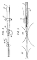
- the cable sheath 2 is carried beneath the wheel 27 by a brazing anvil 28 which consists of a grooved roller on a cantilevered shaft, as shown more clearly in Figure 8.
- the bulk of the cable lies in the groove of the anvil 28 and the fins are supported on a flat surface adjacent to the groove.
- the amount of contact between the wheel 27 and the fin is controlled by vertical movement of the brazing anvil 28 by means of a stepper motor 38, a belt 39 and two slides 35, 36, on the upper 35 of which the anvil 28 is mounted through a button-type load cell 37.
- the anvil 28 is water cooled and the wheel 27 is cooled by means of cold air provided by passing compressed air through a vortex tube 30, the air then being directed via the wheel guard 29 onto the periphery of the wheel 27.
- the process is also monitored in the present case by focusing an infra-red thermometer 31 or any other suitable means, onto the track left by the wheel 27.
- the bonded sheath 2 then passes under a flat roller 32, which helps to prevent the sheath from twisting in the brazing anvil 28, and then passes through an anti-twist guide block 33 and a fin-closing die 34.
- the fin-closing die 34 is in the present embodiment made of steel and water cooled. It folds the still protruding fins against the periphery of the sheath 2 so that the sheath 2 has the cross-section shown in Figure 15.
- the weighted roller 6 shown in Figure 1 forms a detecting means for detecting the absence of or insufficient tension in the brazing wire 1 and is mounted on an arm about a pivot. If the tension in the brazing wire 1 is sufficient, the weighted roller 6 is maintained in the condition shown in Figure 1. If the tension in the wire 1 becomes too low, or if there is no more brazing wire 1, however, the weighted roller 6 pivots downwards on the arm and operates a switching means 11 for switching off the moving parts of the apparatus.
- a similar detecting and switching arrangement may be included to detect the absence of or too low a tension in the copper strip 2 and to shut down the moving parts of the apparatus in response to such a detection, though such an additional arrangement is not shown in the figures.
- an alternative construction of the frictional means may be used, i.e. not using wheels, or the apparatus, instead of receiving a copper strip and brazing wire at one end and continuously delivering manufactured metal tubing with cable core therein at the other end, may be an apparatus which moves along a copper strip which is fixed in position.
- detecting means in the form of weighted rollers, optical or any other suitable detectors may be used.
- edge portions to be bonded into a fin arrangement as shown in Figure 15 may alternatively be simply overlapped in a wrap-around arrangement if the materials of the metal strip or the contents of the tube provide sufficient support during manufacture.
Landscapes
- Engineering & Computer Science (AREA)
- Mechanical Engineering (AREA)
- Manufacturing & Machinery (AREA)
- Wire Processing (AREA)
- Bending Of Plates, Rods, And Pipes (AREA)
Applications Claiming Priority (2)
| Application Number | Priority Date | Filing Date | Title |
|---|---|---|---|
| GB9008659A GB2243097B (en) | 1990-04-18 | 1990-04-18 | Manufacture of metal tubes |
| GB9008659 | 1990-04-18 |
Publications (2)
| Publication Number | Publication Date |
|---|---|
| EP0453182A1 true EP0453182A1 (de) | 1991-10-23 |
| EP0453182B1 EP0453182B1 (de) | 1995-02-22 |
Family
ID=10674576
Family Applications (1)
| Application Number | Title | Priority Date | Filing Date |
|---|---|---|---|
| EP91303203A Expired - Lifetime EP0453182B1 (de) | 1990-04-18 | 1991-04-11 | Metallrohrherstellung |
Country Status (7)
| Country | Link |
|---|---|
| US (1) | US5129571A (de) |
| EP (1) | EP0453182B1 (de) |
| JP (1) | JPH0557339A (de) |
| CA (1) | CA2040665A1 (de) |
| DE (1) | DE69107503T2 (de) |
| ES (1) | ES2068504T3 (de) |
| GB (1) | GB2243097B (de) |
Cited By (7)
| Publication number | Priority date | Publication date | Assignee | Title |
|---|---|---|---|---|
| WO2000051776A1 (en) * | 1999-03-03 | 2000-09-08 | Evelyn Frances Gray | High speed metal joining process |
| WO2013002869A3 (en) * | 2011-04-07 | 2013-02-28 | Schultz-Creehan Holdings, Inc. | System for continuous feeding of filler material for friction stir fabrication and self-reacting friction stir welding tool |
| US9643279B2 (en) | 2005-09-26 | 2017-05-09 | Aeroprobe Corporation | Fabrication tools for exerting normal forces on feedstock |
| US9862054B2 (en) | 2013-12-18 | 2018-01-09 | Aeroprobe Corporation | Additive friction stir methods of repairing substrates |
| US10105790B2 (en) | 2014-12-17 | 2018-10-23 | Aeroprobe Corporation | Solid state joining using additive friction stir processing |
| US10583631B2 (en) | 2014-12-17 | 2020-03-10 | MELD Manufacturing Corporation | In-situ interlocking of metals using additive friction stir processing |
| US11311959B2 (en) | 2017-10-31 | 2022-04-26 | MELD Manufacturing Corporation | Solid-state additive manufacturing system and material compositions and structures |
Families Citing this family (2)
| Publication number | Priority date | Publication date | Assignee | Title |
|---|---|---|---|---|
| GB9309822D0 (en) * | 1993-05-13 | 1993-06-23 | Allwood Searle & Timney | Improvements relating to friction welding |
| US20060157539A1 (en) * | 2005-01-19 | 2006-07-20 | Dubois Jon D | Hot reduced coil tubing |
Citations (3)
| Publication number | Priority date | Publication date | Assignee | Title |
|---|---|---|---|---|
| DE520305C (de) * | 1927-10-08 | 1931-03-09 | Bundy Tubing Co | Verfahren zur Herstellung eines zweischichtigen Verbundrohres |
| DE954775C (de) * | 1950-04-18 | 1956-12-20 | British Insulated Callenders | Verfahren und Einrichtung zum Herstellen von Rohren aus Metallstreifen, insbesondere fuer elektrische Kabel |
| AT326980B (de) * | 1972-04-20 | 1976-01-12 | Luc Jane | Verfahren und einrichtung zum direkten verbinden von metallteilen |
Family Cites Families (5)
| Publication number | Priority date | Publication date | Assignee | Title |
|---|---|---|---|---|
| US2032271A (en) * | 1933-10-25 | 1936-02-25 | Winford L Enghauser | Pipe forming process |
| GB727684A (en) * | 1951-09-10 | 1955-04-06 | Bundy Tubing Co | Improvements in metal tubing and method of making the same |
| GB1224891A (en) * | 1966-09-01 | 1971-03-10 | Penelope Jane Vesey Luc | Improvements in or relating to apparatus and processes for causing adhesion or cohesion together of materials |
| DE2102020A1 (de) * | 1971-01-16 | 1972-09-21 | Luc J | Klebeverfahren, Einrichtungen zur Durchfuhrung des Verfahrens und Anwen düngen des Verfahrens |
| US3949896A (en) * | 1970-10-23 | 1976-04-13 | Penelope Jane Vesey Luc | Seamed article |
-
1990
- 1990-04-18 GB GB9008659A patent/GB2243097B/en not_active Expired - Fee Related
-
1991
- 1991-04-11 US US07/683,781 patent/US5129571A/en not_active Expired - Fee Related
- 1991-04-11 EP EP91303203A patent/EP0453182B1/de not_active Expired - Lifetime
- 1991-04-11 ES ES91303203T patent/ES2068504T3/es not_active Expired - Lifetime
- 1991-04-11 DE DE69107503T patent/DE69107503T2/de not_active Expired - Fee Related
- 1991-04-17 CA CA002040665A patent/CA2040665A1/en not_active Abandoned
- 1991-04-18 JP JP3114053A patent/JPH0557339A/ja active Pending
Patent Citations (3)
| Publication number | Priority date | Publication date | Assignee | Title |
|---|---|---|---|---|
| DE520305C (de) * | 1927-10-08 | 1931-03-09 | Bundy Tubing Co | Verfahren zur Herstellung eines zweischichtigen Verbundrohres |
| DE954775C (de) * | 1950-04-18 | 1956-12-20 | British Insulated Callenders | Verfahren und Einrichtung zum Herstellen von Rohren aus Metallstreifen, insbesondere fuer elektrische Kabel |
| AT326980B (de) * | 1972-04-20 | 1976-01-12 | Luc Jane | Verfahren und einrichtung zum direkten verbinden von metallteilen |
Cited By (8)
| Publication number | Priority date | Publication date | Assignee | Title |
|---|---|---|---|---|
| WO2000051776A1 (en) * | 1999-03-03 | 2000-09-08 | Evelyn Frances Gray | High speed metal joining process |
| US9643279B2 (en) | 2005-09-26 | 2017-05-09 | Aeroprobe Corporation | Fabrication tools for exerting normal forces on feedstock |
| WO2013002869A3 (en) * | 2011-04-07 | 2013-02-28 | Schultz-Creehan Holdings, Inc. | System for continuous feeding of filler material for friction stir fabrication and self-reacting friction stir welding tool |
| US9862054B2 (en) | 2013-12-18 | 2018-01-09 | Aeroprobe Corporation | Additive friction stir methods of repairing substrates |
| US10500674B2 (en) | 2013-12-18 | 2019-12-10 | MELD Manufacturing Corporation | Additive friction-stir fabrication system for forming substrates with ribs |
| US10105790B2 (en) | 2014-12-17 | 2018-10-23 | Aeroprobe Corporation | Solid state joining using additive friction stir processing |
| US10583631B2 (en) | 2014-12-17 | 2020-03-10 | MELD Manufacturing Corporation | In-situ interlocking of metals using additive friction stir processing |
| US11311959B2 (en) | 2017-10-31 | 2022-04-26 | MELD Manufacturing Corporation | Solid-state additive manufacturing system and material compositions and structures |
Also Published As
| Publication number | Publication date |
|---|---|
| EP0453182B1 (de) | 1995-02-22 |
| DE69107503T2 (de) | 1995-06-14 |
| CA2040665A1 (en) | 1991-10-19 |
| ES2068504T3 (es) | 1995-04-16 |
| US5129571A (en) | 1992-07-14 |
| GB2243097B (en) | 1994-01-26 |
| GB9008659D0 (en) | 1990-06-13 |
| JPH0557339A (ja) | 1993-03-09 |
| GB2243097A (en) | 1991-10-23 |
| DE69107503D1 (de) | 1995-03-30 |
Similar Documents
| Publication | Publication Date | Title |
|---|---|---|
| EP0299123B1 (de) | Vorrichtung und Verfahren zur kontinuierlichen Fertigung von bewehrten optischen Kabeln | |
| US5129571A (en) | Manufacture of metal tubes | |
| US8141403B2 (en) | Method for bending pipes, rods, profiled sections and similar blanks, and corresponding device | |
| CN1128685A (zh) | 纵缝焊接的金属管的制造方法 | |
| CN112912187B (zh) | 电缆加工机的矫直装置和用于操作矫直机构的方法 | |
| US5119984A (en) | Manufacture of metal tubes | |
| JPS6031572B2 (ja) | 直線状の帯材から環状体を成形する方法 | |
| US6936124B2 (en) | Wire joint detecting apparatus | |
| EP0566733B1 (de) | Verfahren und vorrichtung zur kontinuierlichen herstellung von metallbändern | |
| US4514900A (en) | Apparatus to manufacture heat exchanger finned tube | |
| EP0581493B1 (de) | Verfahren und Ausrüstung für den automatischen Übergang des zugeführten Drahtes in einer Funkenerosionsmaschine | |
| US5406818A (en) | Opening apparatus having an alignment system for producing a continuous metal strip from a split-tube | |
| US7143622B2 (en) | Extruded composite profile and method for separately winding two individual simultaneously extruded tubes with the aid of a winding device | |
| EP0163520A2 (de) | Verfahren und Vorrichtung zur Herstellung von Gleitlagern | |
| CN220199674U (zh) | 一种换热器芯体自动捆扎设备 | |
| CN113044629B (zh) | 轧线上的激光焊接装置 | |
| JP3160786B2 (ja) | 電線端末処理機の測長挟持機構 | |
| US5701648A (en) | Multi-functional fabricating system for welding electrodes | |
| EP0751593A2 (de) | Drahtzuführungsmechanismus und sein Gebrauch in einer Drahtzuführungseinheit einer Drahtschneidvorrichtung | |
| US1464583A (en) | Tube-forming machine | |
| JP3197387B2 (ja) | 異形横断面形状の長尺材の製造方法および装置 | |
| JPH09174254A (ja) | 溶接h形鋼の製造方法 | |
| JPH06155148A (ja) | 定尺整直切断装置 |
Legal Events
| Date | Code | Title | Description |
|---|---|---|---|
| PUAI | Public reference made under article 153(3) epc to a published international application that has entered the european phase |
Free format text: ORIGINAL CODE: 0009012 |
|
| AK | Designated contracting states |
Kind code of ref document: A1 Designated state(s): DE ES FR GB IT |
|
| 17P | Request for examination filed |
Effective date: 19911210 |
|
| 17Q | First examination report despatched |
Effective date: 19930423 |
|
| GRAA | (expected) grant |
Free format text: ORIGINAL CODE: 0009210 |
|
| AK | Designated contracting states |
Kind code of ref document: B1 Designated state(s): DE ES FR GB IT |
|
| REF | Corresponds to: |
Ref document number: 69107503 Country of ref document: DE Date of ref document: 19950330 |
|
| PGFP | Annual fee paid to national office [announced via postgrant information from national office to epo] |
Ref country code: GB Payment date: 19950403 Year of fee payment: 5 |
|
| ITF | It: translation for a ep patent filed | ||
| PGFP | Annual fee paid to national office [announced via postgrant information from national office to epo] |
Ref country code: DE Payment date: 19950410 Year of fee payment: 5 |
|
| PGFP | Annual fee paid to national office [announced via postgrant information from national office to epo] |
Ref country code: FR Payment date: 19950411 Year of fee payment: 5 |
|
| REG | Reference to a national code |
Ref country code: ES Ref legal event code: FG2A Ref document number: 2068504 Country of ref document: ES Kind code of ref document: T3 |
|
| PGFP | Annual fee paid to national office [announced via postgrant information from national office to epo] |
Ref country code: ES Payment date: 19950426 Year of fee payment: 5 |
|
| ET | Fr: translation filed | ||
| PLBE | No opposition filed within time limit |
Free format text: ORIGINAL CODE: 0009261 |
|
| STAA | Information on the status of an ep patent application or granted ep patent |
Free format text: STATUS: NO OPPOSITION FILED WITHIN TIME LIMIT |
|
| 26N | No opposition filed | ||
| PG25 | Lapsed in a contracting state [announced via postgrant information from national office to epo] |
Ref country code: GB Effective date: 19960411 |
|
| PG25 | Lapsed in a contracting state [announced via postgrant information from national office to epo] |
Ref country code: ES Free format text: LAPSE BECAUSE OF NON-PAYMENT OF DUE FEES Effective date: 19960412 |
|
| GBPC | Gb: european patent ceased through non-payment of renewal fee |
Effective date: 19960411 |
|
| PG25 | Lapsed in a contracting state [announced via postgrant information from national office to epo] |
Ref country code: FR Effective date: 19961227 |
|
| PG25 | Lapsed in a contracting state [announced via postgrant information from national office to epo] |
Ref country code: DE Effective date: 19970101 |
|
| REG | Reference to a national code |
Ref country code: FR Ref legal event code: ST |
|
| REG | Reference to a national code |
Ref country code: ES Ref legal event code: FD2A Effective date: 19990503 |
|
| PG25 | Lapsed in a contracting state [announced via postgrant information from national office to epo] |
Ref country code: IT Free format text: LAPSE BECAUSE OF NON-PAYMENT OF DUE FEES;WARNING: LAPSES OF ITALIAN PATENTS WITH EFFECTIVE DATE BEFORE 2007 MAY HAVE OCCURRED AT ANY TIME BEFORE 2007. THE CORRECT EFFECTIVE DATE MAY BE DIFFERENT FROM THE ONE RECORDED. Effective date: 20050411 |