EP0453201A1 - Commande d'un égaliseur adaptif - Google Patents
Commande d'un égaliseur adaptif Download PDFInfo
- Publication number
- EP0453201A1 EP0453201A1 EP91303284A EP91303284A EP0453201A1 EP 0453201 A1 EP0453201 A1 EP 0453201A1 EP 91303284 A EP91303284 A EP 91303284A EP 91303284 A EP91303284 A EP 91303284A EP 0453201 A1 EP0453201 A1 EP 0453201A1
- Authority
- EP
- European Patent Office
- Prior art keywords
- amplifiers
- data
- delay elements
- adder
- inputted
- Prior art date
- Legal status (The legal status is an assumption and is not a legal conclusion. Google has not performed a legal analysis and makes no representation as to the accuracy of the status listed.)
- Granted
Links
Images

Classifications
-
- H—ELECTRICITY
- H04—ELECTRIC COMMUNICATION TECHNIQUE
- H04L—TRANSMISSION OF DIGITAL INFORMATION, e.g. TELEGRAPHIC COMMUNICATION
- H04L25/00—Baseband systems
- H04L25/02—Details ; arrangements for supplying electrical power along data transmission lines
- H04L25/03—Shaping networks in transmitter or receiver, e.g. adaptive shaping networks
- H04L25/03006—Arrangements for removing intersymbol interference
- H04L25/03012—Arrangements for removing intersymbol interference operating in the time domain
- H04L25/03019—Arrangements for removing intersymbol interference operating in the time domain adaptive, i.e. capable of adjustment during data reception
- H04L25/03038—Arrangements for removing intersymbol interference operating in the time domain adaptive, i.e. capable of adjustment during data reception with a non-recursive structure
-
- H—ELECTRICITY
- H03—ELECTRONIC CIRCUITRY
- H03H—IMPEDANCE NETWORKS, e.g. RESONANT CIRCUITS; RESONATORS
- H03H21/00—Adaptive networks
- H03H21/0012—Digital adaptive filters
Definitions
- the present invention relates to a control for an adaptive equalizer which is applied to a high transmission rate digital mobile communication system.
- the present invention relates to a control for an equalizer disposed between an antenna for a receiver in a digital mobile communication system and a signal processing circuit (demodulator and the like) for outputting to the signal processing in unit an optimum signal (reference signal) of the inputted signals which have not been influenced by disturbances between a transmitter and the receiver since some of the signals transmitted from the transmitter are directly inputted to the receiver without being influenced while the other signals are reflected by buildings to cause fading or delayed by the reflection.
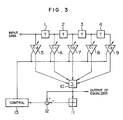
- Fig. 3 shows a prior art control for an adaptive equalizer.
- a reference numeral 1 denotes a delay element for delaying an inputted data.
- Reference numerals 2 through 4 denote delay elements for delaying data from the delay elements 1 through 3 at the previous stage.
- Reference numerals 5 through 9 denote amplifiers for weighting the input data to the delay element and the output data (tap output) from the delay elements 1 through 4, respectively.
- a reference numeral 10 denotes an adder for adding the outputs from the amplifiers 5 through 9.
- the delay elements 1 through 4, the amplifier 5 through 9 and the adder 10 form an equalizer.
- Reference numerals 11 and 12 denote a discriminator for presuming the level of a reference signal from the output of the adder 10 and a subtracter for subtracting the level of the reference signal from the discriminator 11 from the level of the output of the adder 10, respectively.
- control 13 performs operation of the gains of all the amplifiers 5 through 9 by ZF or LMS method and updates the gains each time when the data are inputted to the delay elements 1 through 4 so that the inputted data are equalized.
- the LMS method has a problem in a prior art control for an adaptive equalizer that this method cannot be used for high rate communication since operation speed is slow.
- the ZF method has a difficulty in convergence and has a problem that the inputted data cannot be equalized particularly when it is used for the digital mobile communication in which the signals are generated in a burst manner.
- the present invention was made for overcoming the above mentioned problems.
- the gains of the amplifiers are sequentially operated by the LMS method and updated each time when data are inputted to delay elements for overcoming the above mentioned problems.
- the present invention has advantages that the LMS method having a low operation speed can be used for high transmission rate communication and that the convergence speed is fast since the operation is performed by the LMS method.
- Fig. 1 is a block diagrams showing an embodiment of a control for an adaptive equalizer of the present invention in which components which are like to those in Fig. 3 are designated with like numerals.
- a reference numeral 1 denotes a delay element for delaying an inputted data.
- Reference numerals 2 through 4 denote delay elements for delaying data from the delay elements 1 through 3 at the previous stage. Each delay element include a latch.
- Reference numerals 5 through 9 denote amplifiers for weighting the input data to the delay element and the output data (tap output) from the delay elements 1 through 4, respectively.
- a reference numeral 10 denotes an adder for adding the outputs from the amplifiers 5 through 9.
- the delay elements 1 through 4, the amplifier 5 through 9 and the adder 10 form an equalizer.
- Reference numerals 11 and 12 denote a discriminator for presuming the level of a reference signal from the output of the adder 10 and a subtracter for subtracting the level of the reference signal from the discriminator 11 from the level of the output of the adder 10, respectively.
- Reference numeral 13a denotes a control for sequentially operating each gain of the amplifiers 5 through 9 by the LMS method in predetermined order in accordance with the level of the signal from the subtracter 12 and a reference numeral 14 denotes a control order switching circuit which is switched by the control 13a for outputting the operated gain to the corresponding amplifier.
- Fig. 1 the inputted data are delayed by the serial delay elements 1 through 4 and are stored as a data train and then weighted by the amplifiers 5 through 9 in accordance with the following formula and then added by the adder 10 to provide an output signal to the equalizer.
- the discriminator 11 presumes the level of the reference signal in accordance with an output signal of the equalizer (adder 10) as shown in Fig. 2A and outputs the output signal -1, 0, +1 as shown in Fig. 2B.
- the subtracter 12 subtracts the level of the reference signal from the discriminator 11 from the level of the output signal of the equalizer 10 to output a signal to the control 13a.
- the control 13a operates the gain of one of the amplifiers 5 through 9 in predetermined order and switches the control order switching device 14 for updating the gain of the amplifier in interest to the operated gain.
- the data stored in the delay elements 1 through 4 are sequentially shifted to the subsequent delay elements 2 through 4 and the amplifier 9 and weighted by the amplifiers 5 through 9.
- the weighted signals are added by the adder 10.
- the discriminator 11 presumes the reference signal level in accordance with the output signal of the equalizer and outputs an output signal representative of the reference signal level.
- the subtracter 12 subtracts the reference signal level determined by the discriminator 11 from the output signal level of the equalizer to output a signal representative of the difference to the control 13a.
- the control 13a operates the gain of next one of the amplifiers 5 through 9 in predetermined order and switches the control order switcher 14 for updating the gain of the amplifier in interest to the operated gain.
- control 13a consecutively operates the gain of one of the amplifiers 5 through 9 in predetermined order in accordance with the present embodiment each time when a data is inputted. Therefore, the gain can be updated within an operation period of time which is 1/5 of that required in the prior art in which there are provided five amplifiers 5 through 9.
- the control 13a has an advantage that the convergence is fast since the control performs the operation by the LMS method.
- the gains of one amplifier may be operated at one time, in the present embodiment, the gains of a plurality of amplifiers may be operated at the same time and the amplifiers, the gains of which are to be operated may be sequentially changed at given times.
Landscapes
- Engineering & Computer Science (AREA)
- Power Engineering (AREA)
- Computer Networks & Wireless Communication (AREA)
- Signal Processing (AREA)
- Cable Transmission Systems, Equalization Of Radio And Reduction Of Echo (AREA)
Applications Claiming Priority (2)
| Application Number | Priority Date | Filing Date | Title |
|---|---|---|---|
| JP2100033A JPH03297228A (ja) | 1990-04-16 | 1990-04-16 | 適応等化器制御装置 |
| JP100033/90 | 1990-04-16 |
Publications (2)
| Publication Number | Publication Date |
|---|---|
| EP0453201A1 true EP0453201A1 (fr) | 1991-10-23 |
| EP0453201B1 EP0453201B1 (fr) | 1994-12-21 |
Family
ID=14263217
Family Applications (1)
| Application Number | Title | Priority Date | Filing Date |
|---|---|---|---|
| EP91303284A Expired - Lifetime EP0453201B1 (fr) | 1990-04-16 | 1991-04-12 | Commande d'un égaliseur adaptif |
Country Status (4)
| Country | Link |
|---|---|
| EP (1) | EP0453201B1 (fr) |
| JP (1) | JPH03297228A (fr) |
| DE (1) | DE69106030T2 (fr) |
| ES (1) | ES2064905T3 (fr) |
Cited By (3)
| Publication number | Priority date | Publication date | Assignee | Title |
|---|---|---|---|---|
| EP0554494A1 (fr) * | 1992-02-07 | 1993-08-11 | Siemens Aktiengesellschaft | Filtre numérique non récursif adaptatif |
| US5444739A (en) * | 1991-09-12 | 1995-08-22 | Matsushita Electric Industrial Co., Ltd. | Equalizer for data receiver apparatus |
| WO2006061491A1 (fr) * | 2004-12-08 | 2006-06-15 | France Telecom | Procede pour decider de la valeur d'un signal reçu et recepteur associe |
Citations (3)
| Publication number | Priority date | Publication date | Assignee | Title |
|---|---|---|---|---|
| US3781720A (en) * | 1973-01-04 | 1973-12-25 | Bell Telephone Labor Inc | Automatic tap-gain incrementation of adaptive equalizers |
| US3868603A (en) * | 1973-03-09 | 1975-02-25 | Trt Telecom Radio Electr | Automatic equalizing arrangement for a data transmission channel |
| US3992616A (en) * | 1975-06-24 | 1976-11-16 | Honeywell Inc. | Receiver equalizer apparatus |
-
1990
- 1990-04-16 JP JP2100033A patent/JPH03297228A/ja active Pending
-
1991
- 1991-04-12 EP EP91303284A patent/EP0453201B1/fr not_active Expired - Lifetime
- 1991-04-12 DE DE69106030T patent/DE69106030T2/de not_active Expired - Lifetime
- 1991-04-12 ES ES91303284T patent/ES2064905T3/es not_active Expired - Lifetime
Patent Citations (3)
| Publication number | Priority date | Publication date | Assignee | Title |
|---|---|---|---|---|
| US3781720A (en) * | 1973-01-04 | 1973-12-25 | Bell Telephone Labor Inc | Automatic tap-gain incrementation of adaptive equalizers |
| US3868603A (en) * | 1973-03-09 | 1975-02-25 | Trt Telecom Radio Electr | Automatic equalizing arrangement for a data transmission channel |
| US3992616A (en) * | 1975-06-24 | 1976-11-16 | Honeywell Inc. | Receiver equalizer apparatus |
Non-Patent Citations (1)
| Title |
|---|
| PATENT ABSTRACTS OF JAPAN, unexamined applications, E field, vol. 10, no. 289, October 2, 1986 THE PATENT OFFICE JAPANESE GOVERNMENT page 66 E 442 * |
Cited By (5)
| Publication number | Priority date | Publication date | Assignee | Title |
|---|---|---|---|---|
| US5444739A (en) * | 1991-09-12 | 1995-08-22 | Matsushita Electric Industrial Co., Ltd. | Equalizer for data receiver apparatus |
| US5563911A (en) * | 1991-09-12 | 1996-10-08 | Matsushita Electric Industrial Co., Ltd. | Equalizer for data receiver apparatus |
| EP0554494A1 (fr) * | 1992-02-07 | 1993-08-11 | Siemens Aktiengesellschaft | Filtre numérique non récursif adaptatif |
| US5315621A (en) * | 1992-02-07 | 1994-05-24 | Siemens Aktiengesellschaft | Adaptive nonrecursive digital filter and method for forming filter coefficients therefor |
| WO2006061491A1 (fr) * | 2004-12-08 | 2006-06-15 | France Telecom | Procede pour decider de la valeur d'un signal reçu et recepteur associe |
Also Published As
| Publication number | Publication date |
|---|---|
| ES2064905T3 (es) | 1995-02-01 |
| DE69106030D1 (de) | 1995-02-02 |
| DE69106030T2 (de) | 1995-08-10 |
| EP0453201B1 (fr) | 1994-12-21 |
| JPH03297228A (ja) | 1991-12-27 |
Similar Documents
| Publication | Publication Date | Title |
|---|---|---|
| US5444739A (en) | Equalizer for data receiver apparatus | |
| US6011813A (en) | Blind equalization method and apparatus having reduced complexity | |
| EP0720334A2 (fr) | Egaliseur à décision récursive, pour l'annulation des composantes multivoies courtes et longues, utilisant des symboles de décision retardés en correspondance | |
| US5388123A (en) | Data receiving system | |
| JPH0661878A (ja) | 判定帰還形等化器 | |
| EP0577901A1 (fr) | Procédé et dispositif d'égalisation adaptative | |
| EP0528436A2 (fr) | Dispositif de compensation de la gigue de phase pour un annuleur d'écho | |
| EP0459823A2 (fr) | RÀ©cepteur à diversité utilisant un filtre adapté et un égaliseur à décision récursive | |
| US4769808A (en) | Method of cancelling echoes in full-duplex data transmission system | |
| EP0240056A1 (fr) | Filtre adaptatif pour la formation d'un signal annulateur d'écho dans un système d'émission-réception pour la communication bidirectionnelle numérique sur une paire de conducteurs | |
| US5659584A (en) | Data receiving system for receiving data signal faded and delayed | |
| US4982428A (en) | Arrangement for canceling interference in transmission systems | |
| EP1206032A2 (fr) | Méthode de démodulation de signaux et dispositif de reproduction de données à partir d'un signal reçu | |
| US5440583A (en) | Decision feedback equalizer with second-order recursive filter controlled with two feedback coefficients | |
| JP2718937B2 (ja) | 決定指令制御装置とその調節方法 | |
| EP0453201B1 (fr) | Commande d'un égaliseur adaptif | |
| US6349112B1 (en) | Adaptive equalizer compensating signal distortion on transmission path | |
| SU1474859A1 (ru) | Устройство дл передачи дискретных сигналов в многолучевом канале св зи | |
| JP2888174B2 (ja) | 干渉補償器 | |
| JPS62136133A (ja) | 自動トランスバ−サルフイルタ | |
| JPS5945251B2 (ja) | サンプリング位相制御装置 | |
| JP2592390B2 (ja) | 適応自動等化方式 | |
| JPS59139717A (ja) | 自動等化器 | |
| EP0566362A2 (fr) | Egaliseur à réponse impulsionnelle finie (FIR) adaptatif | |
| JPH06188785A (ja) | 自動等化器 |
Legal Events
| Date | Code | Title | Description |
|---|---|---|---|
| PUAI | Public reference made under article 153(3) epc to a published international application that has entered the european phase |
Free format text: ORIGINAL CODE: 0009012 |
|
| AK | Designated contracting states |
Kind code of ref document: A1 Designated state(s): BE CH DE ES FR GB IT LI NL |
|
| 17P | Request for examination filed |
Effective date: 19911121 |
|
| 17Q | First examination report despatched |
Effective date: 19930618 |
|
| GRAA | (expected) grant |
Free format text: ORIGINAL CODE: 0009210 |
|
| ITF | It: translation for a ep patent filed | ||
| AK | Designated contracting states |
Kind code of ref document: B1 Designated state(s): BE CH DE ES FR GB IT LI NL |
|
| REG | Reference to a national code |
Ref country code: ES Ref legal event code: FG2A Ref document number: 2064905 Country of ref document: ES Kind code of ref document: T3 |
|
| REF | Corresponds to: |
Ref document number: 69106030 Country of ref document: DE Date of ref document: 19950202 |
|
| ET | Fr: translation filed | ||
| PLBE | No opposition filed within time limit |
Free format text: ORIGINAL CODE: 0009261 |
|
| STAA | Information on the status of an ep patent application or granted ep patent |
Free format text: STATUS: NO OPPOSITION FILED WITHIN TIME LIMIT |
|
| 26N | No opposition filed | ||
| K1C1 | Correction of patent application (title page) published |
Effective date: 19911023 |
|
| REG | Reference to a national code |
Ref country code: GB Ref legal event code: IF02 |
|
| REG | Reference to a national code |
Ref country code: CH Ref legal event code: PFA Owner name: MATSUSHITA ELECTRIC INDUSTRIAL CO., LTD Free format text: MATSUSHITA ELECTRIC INDUSTRIAL CO., LTD#1006, OAZA KADOMA#KADOMA-SHI/OSAKA-FU (JP) -TRANSFER TO- MATSUSHITA ELECTRIC INDUSTRIAL CO., LTD#1006, OAZA KADOMA#KADOMA-SHI/OSAKA-FU (JP) |
|
| PGFP | Annual fee paid to national office [announced via postgrant information from national office to epo] |
Ref country code: GB Payment date: 20100325 Year of fee payment: 20 |
|
| PGFP | Annual fee paid to national office [announced via postgrant information from national office to epo] |
Ref country code: FR Payment date: 20100521 Year of fee payment: 20 Ref country code: ES Payment date: 20100423 Year of fee payment: 20 |
|
| PGFP | Annual fee paid to national office [announced via postgrant information from national office to epo] |
Ref country code: NL Payment date: 20100416 Year of fee payment: 20 Ref country code: IT Payment date: 20100419 Year of fee payment: 20 Ref country code: DE Payment date: 20100430 Year of fee payment: 20 Ref country code: BE Payment date: 20100322 Year of fee payment: 20 |
|
| PGFP | Annual fee paid to national office [announced via postgrant information from national office to epo] |
Ref country code: CH Payment date: 20100414 Year of fee payment: 20 |
|
| REG | Reference to a national code |
Ref country code: DE Ref legal event code: R071 Ref document number: 69106030 Country of ref document: DE |
|
| REG | Reference to a national code |
Ref country code: NL Ref legal event code: V4 Effective date: 20110412 |
|
| REG | Reference to a national code |
Ref country code: CH Ref legal event code: PL |
|
| BE20 | Be: patent expired |
Owner name: *MATSUSHITA ELECTRIC INDUSTRIAL CO. LTD Effective date: 20110412 |
|
| REG | Reference to a national code |
Ref country code: GB Ref legal event code: PE20 Expiry date: 20110411 |
|
| PG25 | Lapsed in a contracting state [announced via postgrant information from national office to epo] |
Ref country code: GB Free format text: LAPSE BECAUSE OF EXPIRATION OF PROTECTION Effective date: 20110411 Ref country code: NL Free format text: LAPSE BECAUSE OF EXPIRATION OF PROTECTION Effective date: 20110412 |
|
| REG | Reference to a national code |
Ref country code: ES Ref legal event code: FD2A Effective date: 20120510 |
|
| PG25 | Lapsed in a contracting state [announced via postgrant information from national office to epo] |
Ref country code: ES Free format text: LAPSE BECAUSE OF EXPIRATION OF PROTECTION Effective date: 20110413 |
|
| PG25 | Lapsed in a contracting state [announced via postgrant information from national office to epo] |
Ref country code: DE Free format text: LAPSE BECAUSE OF EXPIRATION OF PROTECTION Effective date: 20110412 |