EP0453251B1 - Génération d'images à ultrasons d'une aiguille de biopsie - Google Patents
Génération d'images à ultrasons d'une aiguille de biopsie Download PDFInfo
- Publication number
- EP0453251B1 EP0453251B1 EP91303404A EP91303404A EP0453251B1 EP 0453251 B1 EP0453251 B1 EP 0453251B1 EP 91303404 A EP91303404 A EP 91303404A EP 91303404 A EP91303404 A EP 91303404A EP 0453251 B1 EP0453251 B1 EP 0453251B1
- Authority
- EP
- European Patent Office
- Prior art keywords
- doppler
- biopsy needle
- imaging system
- tip
- cannula
- Prior art date
- Legal status (The legal status is an assumption and is not a legal conclusion. Google has not performed a legal analysis and makes no representation as to the accuracy of the status listed.)
- Expired - Lifetime
Links
- 238000001574 biopsy Methods 0.000 title claims abstract description 59
- 238000003384 imaging method Methods 0.000 title claims abstract description 40
- 230000005540 biological transmission Effects 0.000 claims description 11
- 230000008878 coupling Effects 0.000 claims description 3
- 238000010168 coupling process Methods 0.000 claims description 3
- 238000005859 coupling reaction Methods 0.000 claims description 3
- 230000004044 response Effects 0.000 abstract description 16
- 238000002604 ultrasonography Methods 0.000 abstract description 9
- 238000013459 approach Methods 0.000 abstract description 7
- 210000000746 body region Anatomy 0.000 abstract 2
- 230000007246 mechanism Effects 0.000 description 18
- 238000000034 method Methods 0.000 description 18
- 230000001360 synchronised effect Effects 0.000 description 5
- 238000013519 translation Methods 0.000 description 5
- 230000003595 spectral effect Effects 0.000 description 4
- 238000010586 diagram Methods 0.000 description 3
- 230000010354 integration Effects 0.000 description 3
- 230000010363 phase shift Effects 0.000 description 3
- 238000012800 visualization Methods 0.000 description 3
- 238000002592 echocardiography Methods 0.000 description 2
- 230000035807 sensation Effects 0.000 description 2
- 230000015572 biosynthetic process Effects 0.000 description 1
- 230000008859 change Effects 0.000 description 1
- 239000004020 conductor Substances 0.000 description 1
- 238000010276 construction Methods 0.000 description 1
- 230000002939 deleterious effect Effects 0.000 description 1
- 238000001514 detection method Methods 0.000 description 1
- 229940079593 drug Drugs 0.000 description 1
- 239000003814 drug Substances 0.000 description 1
- 230000000694 effects Effects 0.000 description 1
- 238000005516 engineering process Methods 0.000 description 1
- 230000007717 exclusion Effects 0.000 description 1
- 238000001914 filtration Methods 0.000 description 1
- 238000001727 in vivo Methods 0.000 description 1
- 238000003780 insertion Methods 0.000 description 1
- 230000037431 insertion Effects 0.000 description 1
- 230000000873 masking effect Effects 0.000 description 1
- 238000001208 nuclear magnetic resonance pulse sequence Methods 0.000 description 1
- 238000012545 processing Methods 0.000 description 1
- 239000013598 vector Substances 0.000 description 1
- 230000000007 visual effect Effects 0.000 description 1
Images

Classifications
-
- A—HUMAN NECESSITIES
- A61—MEDICAL OR VETERINARY SCIENCE; HYGIENE
- A61B—DIAGNOSIS; SURGERY; IDENTIFICATION
- A61B8/00—Diagnosis using ultrasonic, sonic or infrasonic waves
- A61B8/08—Clinical applications
- A61B8/0833—Clinical applications involving detecting or locating foreign bodies or organic structures
- A61B8/0841—Clinical applications involving detecting or locating foreign bodies or organic structures for locating instruments
-
- A—HUMAN NECESSITIES
- A61—MEDICAL OR VETERINARY SCIENCE; HYGIENE
- A61B—DIAGNOSIS; SURGERY; IDENTIFICATION
- A61B17/00—Surgical instruments, devices or methods
- A61B17/34—Trocars; Puncturing needles
- A61B17/3403—Needle locating or guiding means
-
- A—HUMAN NECESSITIES
- A61—MEDICAL OR VETERINARY SCIENCE; HYGIENE
- A61B—DIAGNOSIS; SURGERY; IDENTIFICATION
- A61B8/00—Diagnosis using ultrasonic, sonic or infrasonic waves
- A61B8/08—Clinical applications
- A61B8/0833—Clinical applications involving detecting or locating foreign bodies or organic structures
-
- A—HUMAN NECESSITIES
- A61—MEDICAL OR VETERINARY SCIENCE; HYGIENE
- A61B—DIAGNOSIS; SURGERY; IDENTIFICATION
- A61B17/00—Surgical instruments, devices or methods
- A61B17/22—Implements for squeezing-off ulcers or the like on inner organs of the body; Implements for scraping-out cavities of body organs, e.g. bones; for invasive removal or destruction of calculus using mechanical vibrations; for removing obstructions in blood vessels, not otherwise provided for
- A61B2017/22072—Implements for squeezing-off ulcers or the like on inner organs of the body; Implements for scraping-out cavities of body organs, e.g. bones; for invasive removal or destruction of calculus using mechanical vibrations; for removing obstructions in blood vessels, not otherwise provided for with an instrument channel, e.g. for replacing one instrument by the other
- A61B2017/22074—Implements for squeezing-off ulcers or the like on inner organs of the body; Implements for scraping-out cavities of body organs, e.g. bones; for invasive removal or destruction of calculus using mechanical vibrations; for removing obstructions in blood vessels, not otherwise provided for with an instrument channel, e.g. for replacing one instrument by the other the instrument being only slidable in a channel, e.g. advancing optical fibre through a channel
- A61B2017/22075—Implements for squeezing-off ulcers or the like on inner organs of the body; Implements for scraping-out cavities of body organs, e.g. bones; for invasive removal or destruction of calculus using mechanical vibrations; for removing obstructions in blood vessels, not otherwise provided for with an instrument channel, e.g. for replacing one instrument by the other the instrument being only slidable in a channel, e.g. advancing optical fibre through a channel with motorized advancing or retracting means
-
- A—HUMAN NECESSITIES
- A61—MEDICAL OR VETERINARY SCIENCE; HYGIENE
- A61B—DIAGNOSIS; SURGERY; IDENTIFICATION
- A61B17/00—Surgical instruments, devices or methods
- A61B17/34—Trocars; Puncturing needles
- A61B17/3403—Needle locating or guiding means
- A61B2017/3413—Needle locating or guiding means guided by ultrasound
-
- A—HUMAN NECESSITIES
- A61—MEDICAL OR VETERINARY SCIENCE; HYGIENE
- A61B—DIAGNOSIS; SURGERY; IDENTIFICATION
- A61B90/00—Instruments, implements or accessories specially adapted for surgery or diagnosis and not covered by any of the groups A61B1/00 - A61B50/00, e.g. for luxation treatment or for protecting wound edges
- A61B90/39—Markers, e.g. radio-opaque or breast lesions markers
- A61B2090/3925—Markers, e.g. radio-opaque or breast lesions markers ultrasonic
- A61B2090/3929—Active markers
Definitions
- This invention relates to ultrasonic imaging systems and, in particular, to the imaging of biopsy needles by ultrasonic imaging systems during surgical biopsy procedures.
- Surgical biopsy procedures are commonly performed with the assistance of ultrasonic imaging to enable the physician to view the tissue being biopsied. It is of course desirable during such procedures to be able to clearly visualize the needle and monitor its progression through the body as it approaches the tissue mass from which a sample is to be taken.
- Accessories to assist the physician in such procedures are readily available such as biopsy needle guides to be used in conjunction with a transducer scanhead.
- a conventional needle guide attaches to the scanhead to direct the needle to the sector or area of view of the scanhead, thereby mandating that insertion of the needle will follow a path that is confined to the area of the body being imaged.
- Other techniques to more clearly distinguish the needle in the ultrasonic image have also been suggested, such as the formation of a diffraction grating on the needle.
- the diffraction grating is designed to cause the returning ultrasonic echoes from the needle to be more intense, and hence more readily distinguishable than would otherwise be the case.
- an ultrasonic biopsy needle imaging systems as defined by claims 1 and 2.
- the present invention is advantageous as compared with the aforementioned active techniques in that no invasive transducers are employed and system integration may be minimized.
- the present invention is also advantageous as compared with the aforementioned technique of hand manipulating the needle in that the tip of the biopsy needle is preferentially and continuously visualized.
- An apparatus constructed in accordance with the principles of the present invention employs means for mechanically reciprocating a biopsy needle, and preferably a stylet carried by a biopsy needle.
- the frequency of reciprocation is a low audible frequency. Such mechanical reciprocation causes low amplitude motion at the tip of the needle, which is readily detectable by use of Doppler techniques.
- the detected mechanical motion at the needle tip is translated by Doppler detection into locational representation of the needle tip in the image of the tissue being biopsied.
- means for mechanically reciprocating a biopsy needle or stylet is connected to the needle or stylet.
- the needle or stylet motion is detected by a Doppler imaging system as the biopsy procedure is being performed.
- the cycle reciprocation of the needle or stylet is synchronized with the Doppler scanning sequence. This enables the needle tip to be displayed in a constant hue of a predetermined color for positive identification of the needle tip in an ultrasonic image of the tissue structure.
- the representation of the needle tip can obscure the structural image of the tissue which is to be biopsied. This will impair the ability of the physician to precisely locate the needle tip in proximity to the target tissue.
- the representation of the Doppler signal response of the needle tip provides a color modulation of the image of the tissue structure.
- the target tissue is at all times visible to the physician and is not obscured by the Doppler signal response of the needle tip, and the hue and intensity of the color of the target tissue provides a precise indication of the proximity of the needle tip to the target tissue.
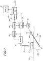
- FIGURE 1 a system for ultrasonically imaging a biopsy needle in accordance with the present invention is illustrated in block diagram form.
- An ultrasonic scanhead 10 including a plurality of imaging transducers 11 is in contact with the surface 30 of the skin of a patient.
- the scanhead 10 is a phased array scanning transducer device.
- the scanhead is connected by a cable 12 to a transmitter and receiver module 14, which provides drivers for supplying energizing pulses or waves to the transducers 11, and receivers for receiving and amplifying electrical signals produced by the transducers in response to the reception of echoes and return signals from the tissue structure being scanned.
- the transducers of the scanhead are energized in a synchronized manner to generate phased array ultrasonic waves under control of a timing and control system 24 connected to the transmitting and receiving module 14.
- the received and amplified electrical signals are demodulated to system baseband signals by a demodulator 16, then stored in a memory or store 18 in positional correspondence to the rays or vectors of interrogation of the phased array scanhead.
- the stored signals are then supplied to a processor 20, where they are filtered by a high pass filter 20a and analyzed by a spectral estimator 20b.
- the spectral estimator provides data which is analyzed for phase shift information as will be described in conjunction with FIGURE 4 below, which information is then translated to positionally representative velocity display information, such as color.
- the display information is then displayed in the desired image format on a display 22.
- the elements thus far described are those of a color flow imaging system such as that employed in the Ultramark 9 color flow imaging system available from Advanced Technology Laboratories, Inc. of Bothell
- a bioopsy needle including a hollow cannula 40 with a tapered and pointed distal tip. Carried within the cannula as it is inserted into the tissue is a removable member 42 extending to the pointed tip, such as a stylet. The proximal end of the member 42 is coupled to a mechanism 44 which longitudinally reciprocates the member or stylet.
- the mechanism 44 may be any one of a variety of devices which generate linear reciprocating motion, such as a linear motor, solenoid, speaker coil, or other device capable of developing and coupling longitudinal reciprocating motion to the member 42.
- the mechanism 44 is energized by an oscillator 46 which develops an appropriate energizing waveform for the mechanism, such as a sine wave, pulse, sawtooth or other waveform.
- an oscillator 46 which develops an appropriate energizing waveform for the mechanism, such as a sine wave, pulse, sawtooth or other waveform.
- the oscillator waveform is synchronized with the energization of the transducers 11 of the scanhead by connection of the oscillator 46 to the timing and control system 24, thereby synchronizing the motion of the member 42 with the rays of the scanhead for clear and continuous visualization of the biopsy needle.
- the method of using the biopsy needle of the present invention is as follows.
- the scanhead 10 is placed against the tissue surface 30 and maneuvered until the mass 31 to be biopsied is viewed in the image sector.
- the image sector is represented in FIGURE 1 by the dashed sector boundaries 32a and 32b on either side of the mass 31.
- the mechanism 44 is connected to member 42 of the biopsy needle and energized to longitudinally reciprocate the member 42 within the cannula 40.
- the biopsy needle is then inserted into the tissue and directed toward the mass 31 and into the field of view of the scanhead. As the needle comes into the field of view, the motion of the vibrating member at the tip of the cannula causes a Doppler response by the imaging system.
- the Doppler response is indicated positionally in the structural ultrasound image as by a color spot or dot.
- the color spot or dot indicates the position of the motion of the member 42 at the cannula tip, and as the biopsy needle is directed toward the mass 31 the color spot will approach the mass 31 in the display image.
- the color spot converges with the mass 31 in the image the cannula 40 is properly positioned to perform a biopsy of the mass.
- the member 42 is withdrawn from the cannula at that point to allow biopsy through the cannula.
- FIGURE 2 a stylet 42' is reciprocated longitudinally within the cannula 40, as indicated by the arrow 43.
- the motion imparted to the stylet is confined in the longitudinal direction to as great a degree as possible.
- the Doppler response of the needle is substantially confined to the very tip of the needle, where the tip of the stylet is reciprocating between its retracted position as shown at 48 and its extended position as indicated by the dashed line at the cannula opening at 48a.
- the range of travel between positions 48 and 48a is only a few millimeters or less, and generally around one millimeter.
- a visual Doppler response is only the motion of the stylet at the open needle tip, to the exclusion of the body of the cannula. Since it is the needle tip that is to be maneuvered precisely to the tissue to be biopsied, it is preferable to have the needle tip highlighted in the image, which is accomplished if the only Doppler response is from the needle tip.
- Radial vibration components can cause motion of the cannula surface, which can undesirably elicit a Doppler response from various locations along the surface of the cannula 40 and hence visualization of this motion in the image in addition to that at the needle tip. This can present a confusing image to the user, who is trying to intently follow the path of the needle tip. By minimizing radial motion component and resulting Doppler responses from the cannula, the accuracy of the biopsy procedure is enhanced.
- the greatest distal extension of the range of travel of the stylet is only to the open end of the cannula, and not beyond. It is desirable to avoid any potential damage to tissue which would be caused by reciprocating the stylet tip beyond the open cannula tip.
- the only cutting of tissue should be that done by the sharpened cannula tip under the controlled manipulation of the surgeon.
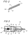
- a mechanism for longitudinally moving member 42 of the biopsy needle of FIGURE 1 is shown in the cross-sectional view of FIGURE 3 of the proximal end of the biopsy needle.
- Attached to the end of the cannula 40 is a cannula hub 50, and attached to the end of the stylet 42' is a stylet hub 52.
- Located around the stylet hub 52 are two spaced annular rings or flanges 72 and 74.
- This proximal end of the biopsy needle fits inside the housing 60 of the reciprocating mechanism.
- a solenoid 62 Inside the proximal end of the housing 60 is a solenoid 62, including a coil 64 and a movable plunger 66 which is threaded at the end 68. Wires 65 from the coil 64 exit from the rear of the housing 60.
- the threaded end of the plunger 66 threads into a reciprocating slider 70, which has an opening at its distal end that engages the stylet hub 52 between the rings 72.
- a rubber O-ring 76 forward of the flange 74 and a rubber bumper 78 rearward of the plunger assist the mechanism at turn-around.
- the solenoid 62 is energized by an appropriate waveform to longitudinally reciprocate the plunger 66 within the coil 64.
- the plunger reciprocates it moves the slider 70 as indicated by the arrow, thereby longitudinally reciprocating the stylet 42' within the cannula 40.
- the O-ring 76 and bumper 78 damp the motion of the mechanism when it reverses its direction.
- a speaker coil arrangement may alternatively be employed, in which a coil is the moving component.
- the speaker coil type of mechanism may be preferred, as it is the lower coil mass which is moving as opposed to the generally larger mass of a solenoid plunger.
- the color flow imaging system described with reference to FIGURE 1 operates by transmitting a series of ultrasound pulses, called an ensemble.
- the ensemble of pulses is sent in a single direction, referred to as a ray line.
- Four such ray lines, R1, R2, R3, and R4 are illustratively shown in FIGURE 4.
- Return signals from the ensemble of pulses are received, demodulated, and stored with respect to position along the ray line, as indicated by positions S1, S2, S3, ... Sn-2, Sn-1, Sn of ray line R1 in FIGURE 4.
- the processing includes high pass filtering of the signal information followed by spectral estimation.
- An important recognition of the present invention is that, although Doppler is commonly referred to by users as having a frequency or frequencies of operation, the spectral estimation does not measure a frequency; it determines a phase shift. It is only when the phase shift is divided by time and presented to the user in this format that a frequency translation is derived.
- the principle of the present invention is that the motion at the tip of the needle has a velocity of translation or range of translation between ray lines, and it is this velocity or range of translation which causes a Doppler response by a color flow imaging system.
- the drive signal for the motive mechanism 44 is illustratively shown as a sawtooth waveform in FIGURE 5a, with turn-around of the mechanism occuring at times to, t1, t2, etc. These turnaround times are synchronized to the commencement of ensemble transmission, or to periods of conventional two-dimensional structural imaging performed between ray line Doppler interrogations.
- FIGURE 5b is drawn in correspondence with the waveform of FIGURE 5a, and illustrates the occurrence of stylet tip turn-around in synchronization with the beginning of every fourth ray line interrogation. In this example, turn-around occurs after the fourth ray line, the eighth, the twelfth, and so forth.
- the timing and control system 24 provides the ray line ensemble synchronizing pulse suitable for use by the oscillating mechanism 46.
- the biopsy needle can be reciprocated over a wide range of frequencies. Audio frequencies have been found to be preferred for their ease of application, preferably frequencies of several hundred Hertz and most preferably below one hundred Hertz. For instance, in a constructed embodiment a sequence of 52 ultrasound pulses were transmitted to interrogate a group of ray lines for Doppler information and to detect structure in a corresponding image sector area. The pulse rate used was 4 KHz. At the end of this pulse sequence the direction of travel of the stylet tip was reversed and the stylet moved in the opposite direction for the same time period. Dividing the pulse rate by the number of pulses corresponding to a full cycle of travel for the stylet, 104 pulses, gives a frequency of approximately 38.5 Hertz, the oscillating frequency for the stylet.
- the mechanism 46 of FIGURE 1 may be housed in or attached to the ultrasound machine and connected to the proximal end of the member 42 by a thin sheathed cable similar to a speedometer cable.
- the mechanism within the ultrasound machine provides the necessary motion, which is carried to the stylet by the cable in the sheath. The user is thereby presented with a very light biopsy needle arrangement connected to the ultrasound machine only by a thin sheath.
- the conventional color flow imaging system strongly emphasizes the flow characteristics in a structure by inserting areas of color into an image where flow is occurring. While highlighting flow, there is no representation of structure in such an image where flow is occurring, as the tissue structure is obscured by the color. This is undesirable in use of the present invention, where the user constantly desires to be able to view the mass which is to be biopsied as the needle tip approaches the mass. Instead of replacing and hence masking the structure of the mass with color as the needle tip approaches the mass, in a preferred embodiment the color representative of the needle tip location is used to modulate the display of the mass. Thus, as the needle tip approaches the mass, the image of the mass will turn color as the needle tip reaches the mass.
- the image of the mass is never obscured by color Doppler; instead, the image of the mass turns brightly colored as the needle tip reaches it.
- the center of the colored area is the location of the needle tip opening where the motion of the stylet tip is generating the Doppler response.
Landscapes
- Health & Medical Sciences (AREA)
- Life Sciences & Earth Sciences (AREA)
- Surgery (AREA)
- Medical Informatics (AREA)
- Animal Behavior & Ethology (AREA)
- Engineering & Computer Science (AREA)
- Biomedical Technology (AREA)
- Heart & Thoracic Surgery (AREA)
- Pathology (AREA)
- Molecular Biology (AREA)
- Nuclear Medicine, Radiotherapy & Molecular Imaging (AREA)
- General Health & Medical Sciences (AREA)
- Public Health (AREA)
- Veterinary Medicine (AREA)
- Physics & Mathematics (AREA)
- Biophysics (AREA)
- Radiology & Medical Imaging (AREA)
- Ultra Sonic Daignosis Equipment (AREA)
Claims (12)
- Système d'imagerie à ultrasons d'une aiguille de biopsie comprenant:un système d'imagerie à ultrasons (20, 22) pour générer une image structurelle de l'intérieur du corps dans lequel un mouvement est représenté de façon déterminée par la transmission et la réception de signaux Doppler par des moyens de réception et de transmission Doppler (10, 14) à une fréquence de répétition d'impulsioins Doppler et l'affichage des signaux de mouvement dérivés Doppler dans ladite image structurelle;une aiguille de biopsie comprenant une cannule creuse (40) ayant une extrémité distale pointue;
caractérisé en ce que ledit dispositif d'imagerie comprend, en outre:des moyens moteurs couplés à ladite aiguille de biopsie pour animer en continu d'un mouvement alternatif l'extrémité de la cannule (40) à une fréquence alternative qui est susceptible d'être détectée par lesdits moyens de réception et de transmission Doppler ; etdes moyens de comptage de temps et de commande (24) agencés pour être couplés auxdits moyens de réception et de transmission Doppler (10, 14), pour commander la transmission des impulsions Doppler à une fréquence de répétition d'impulsions Doppler et pour mesurer les signaux décalés Doppler résultant dudit mouvement alternatif de l'extrémité de la cannule (40), lesdits moyens moteurs (44) étant excités en synchronisation avec lesdites impulsions Doppler pour produire des signaux décalés Doppler susceptibles d'être détectés à ladite fréquence de répétition d'impulsions Doppler, si bien que le mouvément de l'extrémité de la cannule (40) est représenté dans ladite image structurelle de l'intérieur du corps dans une position correspondant à la position de l'extrémité de la cannule (40). - Système d'imagerie à ultrasons d'une aiguille de biopsie comprenant:un système d'imagerie à ultrasons (20, 22) pour générer une image structurelle de l'intérieur du corps dans lequel le mouvement est représenté de façon déterminée par la transmission et la réception de signaux Doppler par des moyens de réception et de transmission Doppler (10, 14) à une fréquence de répétition d'impulsions Doppler et l'affichage des signaux de mouvement dérivés Doppler dans ladite image structurelle;une aiguille de biopsie comprenant une cannule creuse (40) ayant une extrémité distale pointue et supportant un élément amovible (42) dans celle-ci;
caractérisé en ce que ledit système d'imagerie comprend en outre:des moyens moteurs (44) couplés audit élément amovible (42) pour animer en continu d'un mouvement alternatif ledit élément amovible (42) supporté dans la cannule (40) à une fréquence alternative qui est susceptible d'être détectée par lesdits moyens de transmission et de réception Doppler; etdes moyens de comptage de temps et de commande (24) agencés pour être couplés auxdits moyens de transmission et de réception Doppler (10, 14), pour commander la transmission des impulsions Doppler à une fréquence de répétition d'impulsions Doppler et pour mesurer les signaux décalés Doppler résultant dudit mouvement alternatif de l'élément amovible (42), lesdits moyens moteurs (44) étant excités en synchronisation avec lesdites impulsions Doppler pour produire des signaux décalés Doppler susceptibles d'être détectés à ladite fréquence de répétition d'impulsions Doppler, si bien que le mouvement de l'élément amovible (42) est représenté dans ladite image structurelle de l'intérieur du corps dans une position correspondant à la position de l'élément amovible (42). - Système d'imagerie à ultrasons d'une aiguille de biopsie selon la revendication 2, dans lequel ledit élément amovible (42) est agencé pour effectuer un mouvement alternatif entre une première position (48a) dans laquelle l'extrémité distale dudit élément (42) est sensiblement alignée avec l'extrémité distale de ladite cannule (40) et une deuxième position (48) dans laquelle l'extrémité distale dudit élément (42) est rétractée dans ladite cannule (40) par rapport à ladite première position (48a).
- Système d'imagerie à ultrasons d'une aiguille de biopsie selon la revendication 2, dans lequel ledit élément amovible (42) comprend un stylet (42').
- Système d'imagerie à ultrasons d'une aiguille de biopsie selon la revendication 1, comprenant, en outre, un moyen pour coupler le mouvement produit par lesdits moyens moteurs (44) à ladite aiguille de biopsie.
- Système d'imagerie à ultrasons d'une aiguille de biopsie selon la revendication 5, dans lequel ledit moyen de couplage comprend un câble gainé.
- Système d'imagerie à ultrasons d'une aiguille de biopsie selon l'une quelconque des revendications précédentes, dans lequel lesdits moyens moteurs (44) sont agencés pour procurer un mouvement alternatif à une fréquence qui est inférieure à 1000 Hz.
- Système d'imagerie à ultrasons d'une aiguille de biopsie selon la revendication 7, dans lequel lesdits moyens moteurs (44) sont agencés pour procurer un mouvement alternatif à une fréquence qui est inférieure à 100 Hz.
- Système d'imagerie à ultrasons d'une aiguille de biopsie selon l'une quelconque des revendications 1 à 8, dans lequel lesdits moyens moteurs (44) comprennent un solénoïde (62).
- Système d'imagerie à ultrasons d'une aiguille de biopsie selon l'une quelconque des revendications 1 à 8, dans lequel lesdits moyens moteurs (44) comprennent un enroulement mobile type haut-parleur.
- Système d'imagerie à ultrasons d'une aiguille de biopsie selon l'une quelconque des revendications 1 et 5 à 10, dans lequel lesdits moyens moteurs (44) sont agencés pour procurer un mouvement alternatif le long sensiblement de la direction longitudinale par rapport à ladite aiguille de biopsie.
- Système d'imagerie à ultrasons d'une aiguille de biopsie selon l'une quelconque des revendications 1 et 5 à 11, et agencé pour générer, en outre, une image dans laquelle une structure est représentée de façon déterminée et dans lequel ladite extrémité de ladite cannule (40) est représentée de façon déterminée dans ladite image en modulant ladite image structurelle avec une couleur au voisinage de l'emplacement de ladite extrémité dans ladite image.
Applications Claiming Priority (2)
| Application Number | Priority Date | Filing Date | Title |
|---|---|---|---|
| US511382 | 1990-04-18 | ||
| US07/511,382 US5095910A (en) | 1990-04-18 | 1990-04-18 | Ultrasonic imaging of biopsy needle |
Publications (2)
| Publication Number | Publication Date |
|---|---|
| EP0453251A1 EP0453251A1 (fr) | 1991-10-23 |
| EP0453251B1 true EP0453251B1 (fr) | 1997-08-20 |
Family
ID=24034659
Family Applications (1)
| Application Number | Title | Priority Date | Filing Date |
|---|---|---|---|
| EP91303404A Expired - Lifetime EP0453251B1 (fr) | 1990-04-18 | 1991-04-17 | Génération d'images à ultrasons d'une aiguille de biopsie |
Country Status (5)
| Country | Link |
|---|---|
| US (1) | US5095910A (fr) |
| EP (1) | EP0453251B1 (fr) |
| JP (1) | JP3146018B2 (fr) |
| AT (1) | ATE156984T1 (fr) |
| DE (1) | DE69127310T2 (fr) |
Cited By (2)
| Publication number | Priority date | Publication date | Assignee | Title |
|---|---|---|---|---|
| US11369296B2 (en) | 2011-02-01 | 2022-06-28 | Olberon Medical Innovation Sas | Needle holder |
| EP4308023A4 (fr) * | 2021-03-16 | 2024-12-11 | Francis Medical, Inc. | Systèmes et procédés de thérapie à la vapeur |
Families Citing this family (107)
| Publication number | Priority date | Publication date | Assignee | Title |
|---|---|---|---|---|
| US5230339A (en) * | 1991-06-13 | 1993-07-27 | Array Tech, Inc. | Performance evaluation of ultrasonic examination equipment |
| US5517990A (en) * | 1992-11-30 | 1996-05-21 | The Cleveland Clinic Foundation | Stereotaxy wand and tool guide |
| US5329927A (en) * | 1993-02-25 | 1994-07-19 | Echo Cath, Inc. | Apparatus and method for locating an interventional medical device with a ultrasound color imaging system |
| US5983123A (en) * | 1993-10-29 | 1999-11-09 | United States Surgical Corporation | Methods and apparatus for performing ultrasound and enhanced X-ray imaging |
| ATE191136T1 (de) * | 1993-10-29 | 2000-04-15 | United States Surgical Corp | Vorrichtung zur kombinierten ultraschall- abbildung und röntgen-abbildung |
| GB2287319B (en) * | 1994-03-12 | 1998-02-25 | John Francis Cockburn | Medical apparatus for ultrasonic methods of ultrasonic imaging |
| DE69525270T2 (de) * | 1994-03-12 | 2002-10-17 | Donald Cockburn | Medizinische Nadel zur Verwendung in einem Ultraschallabtastgerät |
| US5425370A (en) * | 1994-03-23 | 1995-06-20 | Echocath, Inc. | Method and apparatus for locating vibrating devices |
| GB2298368B (en) * | 1995-02-22 | 1999-01-20 | John Francis Cockburn | Medical needle assembly for use in ultrasound imaging |
| US5807304A (en) * | 1995-03-09 | 1998-09-15 | Cockburn; John F. | Medical needle for use in ultrasound imaging |
| US5833627A (en) * | 1995-04-13 | 1998-11-10 | United States Surgical Corporation | Image-guided biopsy apparatus and methods of use |
| EP0845959A4 (fr) * | 1995-07-16 | 1998-09-30 | Ultra Guide Ltd | Pointage de guide d'aiguille a mains libres |
| US6231514B1 (en) | 1996-06-26 | 2001-05-15 | Tobo, Llc | Device for use in temporary insertion of a sensor within a patient's body |
| US5820552A (en) * | 1996-07-12 | 1998-10-13 | United States Surgical Corporation | Sonography and biopsy apparatus |
| US5851180A (en) * | 1996-07-12 | 1998-12-22 | United States Surgical Corporation | Traction-inducing compression assembly for enhanced tissue imaging |
| US5758650A (en) * | 1996-09-30 | 1998-06-02 | Siemens Medical Systems, Inc. | Universal needle guide for ultrasonic transducers |
| US5967991A (en) * | 1996-12-03 | 1999-10-19 | Echocath, Inc. | Drive apparatus for an interventional medical device used in an ultrasonic imaging system |
| US6053871A (en) * | 1997-01-21 | 2000-04-25 | William Cook Australia Pty. Ltd | Calibrated hollow probe for use with ultrasound imaging |
| US6109270A (en) * | 1997-02-04 | 2000-08-29 | The United States Of America As Represented By The Administrator Of The National Aeronautics And Space Administration | Multimodality instrument for tissue characterization |
| US5836882A (en) * | 1997-03-17 | 1998-11-17 | Frazin; Leon J. | Method and apparatus of localizing an insertion end of a probe within a biotic structure |
| JP3723663B2 (ja) * | 1997-07-15 | 2005-12-07 | フクダ電子株式会社 | 超音波診断装置 |
| US6027457A (en) * | 1998-06-18 | 2000-02-22 | United States Surgical Corporation | Apparatus and method for securing tissue during ultrasound examination and biopsy |
| EP1171037A4 (fr) | 1999-04-15 | 2004-03-24 | Ultraguide Ltd | Procede et dispositif de detection de la courbure d'un outil vulnerant medical, lors d'interventions medicales |
| US6577904B1 (en) | 2000-03-30 | 2003-06-10 | Cardiac Pacemakers, Inc. | Ultrasound echogenic cardiac lead |
| US6695786B2 (en) * | 2001-03-16 | 2004-02-24 | U-Systems, Inc. | Guide and position monitor for invasive medical instrument |
| US7220239B2 (en) | 2001-12-03 | 2007-05-22 | Ekos Corporation | Catheter with multiple ultrasound radiating members |
| US6875179B2 (en) * | 2002-06-17 | 2005-04-05 | Board Of Trustees Of The University Of Arkansas | Ultrasonic guided catheter deployment system |
| US6716176B1 (en) | 2002-09-30 | 2004-04-06 | Tobo, Llc | Device for use in temporary insertion of a sensor within a patient's body |
| US7010337B2 (en) * | 2002-10-24 | 2006-03-07 | Furnary Anthony P | Method and apparatus for monitoring blood condition and cardiopulmonary function |
| US7329225B2 (en) * | 2003-02-12 | 2008-02-12 | Duke University | Methods, devices, systems and computer program products for oscillating shafts using real time 3D ultrasound |
| US20040260199A1 (en) * | 2003-06-19 | 2004-12-23 | Wilson-Cook Medical, Inc. | Cytology collection device |
| US20050159676A1 (en) * | 2003-08-13 | 2005-07-21 | Taylor James D. | Targeted biopsy delivery system |
| US20050228312A1 (en) * | 2004-03-31 | 2005-10-13 | Vihar Surti | Biopsy needle system |
| US20060089626A1 (en) * | 2004-10-22 | 2006-04-27 | Vlegele James W | Surgical device guide for use with an imaging system |
| US7452357B2 (en) * | 2004-10-22 | 2008-11-18 | Ethicon Endo-Surgery, Inc. | System and method for planning treatment of tissue |
| US7833221B2 (en) * | 2004-10-22 | 2010-11-16 | Ethicon Endo-Surgery, Inc. | System and method for treatment of tissue using the tissue as a fiducial |
| JP2008522705A (ja) * | 2004-12-13 | 2008-07-03 | コーニンクレッカ フィリップス エレクトロニクス エヌ ヴィ | カニューレ挿入システム |
| US8852111B2 (en) * | 2005-09-02 | 2014-10-07 | Ultrasound Ventures, Llc | Ultrasound guidance system |
| US8118743B2 (en) * | 2006-05-26 | 2012-02-21 | Ultrasound Ventures, Llc | Sterile cover |
| US8496593B2 (en) * | 2006-05-26 | 2013-07-30 | Robert Park | Needle guide |
| US7728868B2 (en) | 2006-08-02 | 2010-06-01 | Inneroptic Technology, Inc. | System and method of providing real-time dynamic imagery of a medical procedure site using multiple modalities |
| US7979109B2 (en) * | 2006-10-12 | 2011-07-12 | Lawrence Group Medical Device Trust | Needle driver for magnetic resonance elastography |
| US10182833B2 (en) | 2007-01-08 | 2019-01-22 | Ekos Corporation | Power parameters for ultrasonic catheter |
| ES2471118T3 (es) | 2007-06-22 | 2014-06-25 | Ekos Corporation | Método y aparato para el tratamiento de hemorragias intracraneales |
| US20110263985A1 (en) * | 2007-08-28 | 2011-10-27 | Koninklijke Philips Electronics N.V. | Dual Path Color Doppler Imaging System and Method for Simultaneous Invasive Device Visualization and Vasculature Imaging |
| JP5416900B2 (ja) * | 2007-11-22 | 2014-02-12 | 株式会社東芝 | 超音波診断装置及び穿刺支援用制御プログラム |
| WO2009094646A2 (fr) | 2008-01-24 | 2009-07-30 | The University Of North Carolina At Chapel Hill | Procédés, systèmes et supports lisibles par ordinateur pour ablation guidée par imagerie |
| US8340379B2 (en) * | 2008-03-07 | 2012-12-25 | Inneroptic Technology, Inc. | Systems and methods for displaying guidance data based on updated deformable imaging data |
| WO2009141690A1 (fr) * | 2008-05-23 | 2009-11-26 | Oscillon Ltd | Methode et dispositif de reconnaissance de structure tissulaire par effet doppler |
| US8473027B2 (en) * | 2008-07-03 | 2013-06-25 | Qsum Biopsy Disposables Llc | Process for draping breast MRI imaging coils |
| US9138286B2 (en) * | 2008-10-20 | 2015-09-22 | Nuvue Therapeutics, Inc. | Ultrasound detectable interventional medical device |
| US8554307B2 (en) | 2010-04-12 | 2013-10-08 | Inneroptic Technology, Inc. | Image annotation in image-guided medical procedures |
| US8641621B2 (en) * | 2009-02-17 | 2014-02-04 | Inneroptic Technology, Inc. | Systems, methods, apparatuses, and computer-readable media for image management in image-guided medical procedures |
| US8690776B2 (en) | 2009-02-17 | 2014-04-08 | Inneroptic Technology, Inc. | Systems, methods, apparatuses, and computer-readable media for image guided surgery |
| US11464578B2 (en) | 2009-02-17 | 2022-10-11 | Inneroptic Technology, Inc. | Systems, methods, apparatuses, and computer-readable media for image management in image-guided medical procedures |
| US8388550B2 (en) * | 2009-05-19 | 2013-03-05 | Cook Medical Technologies Llc | Guidable cutting instrument |
| US10039527B2 (en) | 2009-05-20 | 2018-08-07 | Analogic Canada Corporation | Ultrasound systems incorporating spatial position sensors and associated methods |
| US8556815B2 (en) * | 2009-05-20 | 2013-10-15 | Laurent Pelissier | Freehand ultrasound imaging systems and methods for guiding fine elongate instruments |
| US8449466B2 (en) * | 2009-05-28 | 2013-05-28 | Edwards Lifesciences Corporation | System and method for locating medical devices in vivo using ultrasound Doppler mode |
| EP2442725B1 (fr) * | 2009-06-18 | 2013-08-21 | Quanta Fluid Solutions Ltd | Dispositif de surveillance d'acces vasculaire |
| US9592029B2 (en) | 2009-06-18 | 2017-03-14 | Quanta Fluid Solutions Ltd. | Vascular access monitoring device |
| US8663110B2 (en) | 2009-11-17 | 2014-03-04 | Samsung Medison Co., Ltd. | Providing an optimal ultrasound image for interventional treatment in a medical system |
| US20110124949A1 (en) * | 2009-11-25 | 2011-05-26 | Qsum Biopsy Disposables Llc | Method and apparatus for stabilizing tubing during a brachytherapy procedure |
| US9486162B2 (en) | 2010-01-08 | 2016-11-08 | Ultrasonix Medical Corporation | Spatial needle guidance system and associated methods |
| EP4122385A1 (fr) * | 2010-05-28 | 2023-01-25 | C. R. Bard, Inc. | Système de guidage d'introduction pour aiguilles et composants médicaux |
| JP5925193B2 (ja) | 2010-06-07 | 2016-05-25 | コーニンクレッカ フィリップス エヌ ヴェKoninklijke Philips N.V. | 経皮的針、血管内カテーテル及び他の侵襲的デバイスの超音波視覚化 |
| EP2454996A1 (fr) * | 2010-11-17 | 2012-05-23 | Samsung Medison Co., Ltd. | Fourniture d'une image ultrasonore optimale pour traitement interventionnel dans un système médical |
| US20120130414A1 (en) * | 2010-11-19 | 2012-05-24 | Corlius Fourie Birkill | Vibrating needle adjustment device |
| WO2012066470A1 (fr) | 2010-11-19 | 2012-05-24 | Koninklijke Philips Electronics N.V. | Procédé de guidage de l'insertion d'un instrument chirurgical avec imagerie ultrasonore en trois dimensions |
| CN102727257B (zh) | 2011-03-31 | 2016-08-03 | 通用电气公司 | 穿刺针可视化方法和装置 |
| ITMO20110272A1 (it) * | 2011-10-27 | 2013-04-28 | Delta Med Srl | Ago-cannula per uso medico |
| CN103169493A (zh) * | 2011-12-20 | 2013-06-26 | 通用电气公司 | 超声探针引导装置、方法及超声系统 |
| US9295449B2 (en) | 2012-01-23 | 2016-03-29 | Ultrasonix Medical Corporation | Landmarks for ultrasound imaging |
| WO2013116240A1 (fr) | 2012-01-30 | 2013-08-08 | Inneroptic Technology, Inc. | Guidage de dispositifs médicaux multiples |
| US8945113B2 (en) | 2012-04-05 | 2015-02-03 | Covidien Lp | Electrosurgical tissue ablation systems capable of detecting excessive bending of a probe and alerting a user |
| GB201301866D0 (en) | 2013-02-01 | 2013-03-20 | Olberon Ltd | Needle location device |
| US9622719B2 (en) | 2013-02-26 | 2017-04-18 | Allen Maizes | Color ultrasound needle |
| US10314559B2 (en) | 2013-03-14 | 2019-06-11 | Inneroptic Technology, Inc. | Medical device guidance |
| US20140276082A1 (en) * | 2013-03-14 | 2014-09-18 | Lumoptik Llc | Ultrasound transducer with needle channel |
| GB201304798D0 (en) * | 2013-03-15 | 2013-05-01 | Univ Dundee | Medical apparatus visualisation |
| GB201305755D0 (en) | 2013-03-28 | 2013-05-15 | Quanta Fluid Solutions Ltd | Re-Use of a Hemodialysis Cartridge |
| CN103340674A (zh) * | 2013-06-27 | 2013-10-09 | 苏州边枫电子科技有限公司 | 基于超声波探头振动检测的穿刺针 |
| GB201314512D0 (en) | 2013-08-14 | 2013-09-25 | Quanta Fluid Solutions Ltd | Dual Haemodialysis and Haemodiafiltration blood treatment device |
| CN103879859A (zh) * | 2014-04-11 | 2014-06-25 | 山东华邦建设集团有限公司 | 一种施工升降机 |
| GB201409796D0 (en) | 2014-06-02 | 2014-07-16 | Quanta Fluid Solutions Ltd | Method of heat sanitization of a haemodialysis water circuit using a calculated dose |
| US9901406B2 (en) | 2014-10-02 | 2018-02-27 | Inneroptic Technology, Inc. | Affected region display associated with a medical device |
| US10188467B2 (en) | 2014-12-12 | 2019-01-29 | Inneroptic Technology, Inc. | Surgical guidance intersection display |
| EP3307388B1 (fr) | 2015-06-10 | 2022-06-22 | Ekos Corporation | Cathéter à ultrasons |
| US9949700B2 (en) | 2015-07-22 | 2018-04-24 | Inneroptic Technology, Inc. | Medical device approaches |
| US11793543B2 (en) | 2015-09-18 | 2023-10-24 | Obvius Robotics, Inc. | Device and method for automated insertion of penetrating member |
| WO2017049146A1 (fr) * | 2015-09-18 | 2017-03-23 | Actuated Medical, Inc. | Dispositif et système pour insertion d'élément de pénétration |
| BR112018008198A2 (pt) * | 2015-10-27 | 2018-10-23 | Koninklijke Philips N.V. | dispositivo de sonda, cateter e sistema |
| GB201523104D0 (en) | 2015-12-30 | 2016-02-10 | Quanta Fluid Solutions Ltd | Dialysis machine |
| GB2547214A (en) | 2016-02-10 | 2017-08-16 | Quanta Fluid Solutions Ltd | Membrane pump usage condition detection |
| US9675319B1 (en) | 2016-02-17 | 2017-06-13 | Inneroptic Technology, Inc. | Loupe display |
| US10939905B2 (en) | 2016-08-26 | 2021-03-09 | Edwards Lifesciences Corporation | Suture clips, deployment devices therefor, and methods of use |
| US10278778B2 (en) | 2016-10-27 | 2019-05-07 | Inneroptic Technology, Inc. | Medical device navigation using a virtual 3D space |
| GB201622119D0 (en) | 2016-12-23 | 2017-02-08 | Quanta Dialysis Tech Ltd | Improved valve leak detection system |
| GB201701740D0 (en) | 2017-02-02 | 2017-03-22 | Quanta Dialysis Tech Ltd | Phased convective operation |
| GB201705273D0 (en) | 2017-03-31 | 2017-05-17 | Quanta Dialysis Tech Ltd | Data storage amd exchange by medical device components |
| GB201710546D0 (en) | 2017-06-30 | 2017-08-16 | Quanta Dialysis Tech Ltd | Dialysis systems, devices and methods |
| US11259879B2 (en) | 2017-08-01 | 2022-03-01 | Inneroptic Technology, Inc. | Selective transparency to assist medical device navigation |
| USD907211S1 (en) | 2017-09-28 | 2021-01-05 | Quanta Dialysis Technologies Ltd. | Dialysis machine |
| CN111315300B (zh) * | 2017-09-29 | 2025-02-11 | 巴德股份有限公司 | 用于跟踪医疗超声对象的装置和方法 |
| US11484365B2 (en) | 2018-01-23 | 2022-11-01 | Inneroptic Technology, Inc. | Medical image guidance |
| GB2584335A (en) | 2019-05-31 | 2020-12-02 | Quanta Dialysis Technologies Ltd | Source container connector |
| US12426965B2 (en) | 2023-06-15 | 2025-09-30 | Obvius Robotics, Inc. | Image-guided robotic arm for inserting a penetrating member into a body lumen |
Family Cites Families (10)
| Publication number | Priority date | Publication date | Assignee | Title |
|---|---|---|---|---|
| US3556079A (en) * | 1967-05-16 | 1971-01-19 | Haruo Omizo | Method of puncturing a medical instrument under guidance of ultrasound |
| US3570476A (en) * | 1968-11-18 | 1971-03-16 | David Paul Gregg | Magnetostrictive medical instrument |
| US3805787A (en) * | 1972-06-16 | 1974-04-23 | Surgical Design Corp | Ultrasonic surgical instrument |
| JPS5558154A (en) * | 1978-10-24 | 1980-04-30 | Toshimitsu Mushiya | Electronic diagnosis device |
| US4401124A (en) * | 1981-08-13 | 1983-08-30 | Technicare Corporation | Reflection enhancement of a biopsy needle |
| US4407294A (en) * | 1982-01-07 | 1983-10-04 | Technicare Corporation | Ultrasound tissue probe localization system |
| US4428379A (en) * | 1982-01-07 | 1984-01-31 | Technicare Corporation | Passive ultrasound needle probe locator |
| US4431006A (en) * | 1982-01-07 | 1984-02-14 | Technicare Corporation | Passive ultrasound needle probe locator |
| DE3311804C2 (de) * | 1983-03-31 | 1994-08-04 | Hans J Dr Einighammer | Verfahren und Vorrichtung für die hervorgehobene sonographische Darstellung von Nadelspitzen |
| US4816018A (en) * | 1985-08-02 | 1989-03-28 | Ultramed Corporation | Ultrasonic probe tip |
-
1990
- 1990-04-18 US US07/511,382 patent/US5095910A/en not_active Expired - Fee Related
-
1991
- 1991-04-17 DE DE69127310T patent/DE69127310T2/de not_active Expired - Fee Related
- 1991-04-17 EP EP91303404A patent/EP0453251B1/fr not_active Expired - Lifetime
- 1991-04-17 AT AT91303404T patent/ATE156984T1/de active
- 1991-04-18 JP JP08663491A patent/JP3146018B2/ja not_active Expired - Fee Related
Non-Patent Citations (1)
| Title |
|---|
| "Motion marking in color Doppler ultrasound needle and catheter visualization", T. Kurohiji et al., Journal of Ultrasound in Medicine, Vol. 9, pages 243-245, 1990. * |
Cited By (2)
| Publication number | Priority date | Publication date | Assignee | Title |
|---|---|---|---|---|
| US11369296B2 (en) | 2011-02-01 | 2022-06-28 | Olberon Medical Innovation Sas | Needle holder |
| EP4308023A4 (fr) * | 2021-03-16 | 2024-12-11 | Francis Medical, Inc. | Systèmes et procédés de thérapie à la vapeur |
Also Published As
| Publication number | Publication date |
|---|---|
| JP3146018B2 (ja) | 2001-03-12 |
| US5095910A (en) | 1992-03-17 |
| DE69127310D1 (de) | 1997-09-25 |
| EP0453251A1 (fr) | 1991-10-23 |
| DE69127310T2 (de) | 1998-01-22 |
| ATE156984T1 (de) | 1997-09-15 |
| JPH04227239A (ja) | 1992-08-17 |
Similar Documents
| Publication | Publication Date | Title |
|---|---|---|
| EP0453251B1 (fr) | Génération d'images à ultrasons d'une aiguille de biopsie | |
| EP0755223B1 (fr) | Appareil pour localiser des dispositifs medicaux vibrants | |
| US5799655A (en) | Method and apparatus for ultrasound imaging and atherectomy | |
| JP4443672B2 (ja) | 超音波診断装置 | |
| CN108027437B (zh) | 具有宽深度和详细查看的超声系统 | |
| EP0547159B1 (fr) | Systeme d'imagerie par ultrasons et sonde acoustique | |
| US9155518B2 (en) | Ultrasound imaging apparatus and method for generating ultrasound image | |
| US6685644B2 (en) | Ultrasound diagnostic apparatus | |
| EP3013245B1 (fr) | Injection d'une forme dans une image ultrasonore de façon à étalonner en temps réel des motifs de faisceau | |
| US20130158390A1 (en) | Ultrasonic needle guiding apparatus, method and system | |
| US5549112A (en) | Medical needle for use in ultrasound imaging and method of enhancing the visibility of such a needle to ultrasound | |
| US20170188991A1 (en) | High quality closed-loop ultrasound imaging system | |
| JPH0643242A (ja) | 超音波イメージ化システム | |
| KR20190088165A (ko) | 초음파 영상장치 및 그 제어방법 | |
| EP2039297B9 (fr) | Appareil de diagnostic à ultrasons | |
| CN101784235A (zh) | 用于同时进行的侵入性设备可视化和脉管系统成像的双路径彩色多普勒成像系统和方法 | |
| WO2015092628A1 (fr) | Systèmes d'imagerie échographique et procédés de localisation pour suivre les emplacements d'un dispositif médical invasif | |
| US5421336A (en) | Method for attaching an interventional medical device to a vibratory member associated with visualization by an ultrasound imaging system | |
| EP0019793A2 (fr) | Procédé de détermination de la vitesse de matière en mouvement, notamment dans le corps et dispositif pour cette détermination et pour la visualisation de parties du corps | |
| US7329225B2 (en) | Methods, devices, systems and computer program products for oscillating shafts using real time 3D ultrasound | |
| EP3815615A1 (fr) | Systèmes et procédés de positionnement de timbres ultrasonores | |
| GB2367895A (en) | Needle location system for use with ultrasound imager | |
| JPS6090542A (ja) | 超音波診断装置 | |
| EP3849424B1 (fr) | Suivi d'un outil dans une image ultrasonore | |
| Von Ramm et al. | Thaumascan: design considerations and performance characteristics |
Legal Events
| Date | Code | Title | Description |
|---|---|---|---|
| PUAI | Public reference made under article 153(3) epc to a published international application that has entered the european phase |
Free format text: ORIGINAL CODE: 0009012 |
|
| AK | Designated contracting states |
Kind code of ref document: A1 Designated state(s): AT BE CH DE DK ES FR GB GR IT LI LU NL SE |
|
| 17P | Request for examination filed |
Effective date: 19920331 |
|
| 17Q | First examination report despatched |
Effective date: 19940718 |
|
| GRAG | Despatch of communication of intention to grant |
Free format text: ORIGINAL CODE: EPIDOS AGRA |
|
| GRAH | Despatch of communication of intention to grant a patent |
Free format text: ORIGINAL CODE: EPIDOS IGRA |
|
| GRAH | Despatch of communication of intention to grant a patent |
Free format text: ORIGINAL CODE: EPIDOS IGRA |
|
| GRAA | (expected) grant |
Free format text: ORIGINAL CODE: 0009210 |
|
| AK | Designated contracting states |
Kind code of ref document: B1 Designated state(s): AT BE CH DE DK ES FR GB GR IT LI LU NL SE |
|
| PG25 | Lapsed in a contracting state [announced via postgrant information from national office to epo] |
Ref country code: LI Free format text: LAPSE BECAUSE OF FAILURE TO SUBMIT A TRANSLATION OF THE DESCRIPTION OR TO PAY THE FEE WITHIN THE PRESCRIBED TIME-LIMIT Effective date: 19970820 Ref country code: GR Free format text: LAPSE BECAUSE OF FAILURE TO SUBMIT A TRANSLATION OF THE DESCRIPTION OR TO PAY THE FEE WITHIN THE PRESCRIBED TIME-LIMIT Effective date: 19970820 Ref country code: ES Free format text: THE PATENT HAS BEEN ANNULLED BY A DECISION OF A NATIONAL AUTHORITY Effective date: 19970820 Ref country code: DK Free format text: LAPSE BECAUSE OF NON-PAYMENT OF DUE FEES Effective date: 19970820 Ref country code: CH Free format text: LAPSE BECAUSE OF FAILURE TO SUBMIT A TRANSLATION OF THE DESCRIPTION OR TO PAY THE FEE WITHIN THE PRESCRIBED TIME-LIMIT Effective date: 19970820 Ref country code: BE Effective date: 19970820 Ref country code: AT Effective date: 19970820 |
|
| REF | Corresponds to: |
Ref document number: 156984 Country of ref document: AT Date of ref document: 19970915 Kind code of ref document: T |
|
| REG | Reference to a national code |
Ref country code: CH Ref legal event code: EP |
|
| REF | Corresponds to: |
Ref document number: 69127310 Country of ref document: DE Date of ref document: 19970925 |
|
| ET | Fr: translation filed | ||
| ITF | It: translation for a ep patent filed | ||
| PG25 | Lapsed in a contracting state [announced via postgrant information from national office to epo] |
Ref country code: SE Effective date: 19971120 |
|
| K1C1 | Correction of patent application (title page) published |
Effective date: 19911023 |
|
| REG | Reference to a national code |
Ref country code: CH Ref legal event code: PL |
|
| PG25 | Lapsed in a contracting state [announced via postgrant information from national office to epo] |
Ref country code: LU Free format text: LAPSE BECAUSE OF NON-PAYMENT OF DUE FEES Effective date: 19980417 |
|
| PLBE | No opposition filed within time limit |
Free format text: ORIGINAL CODE: 0009261 |
|
| STAA | Information on the status of an ep patent application or granted ep patent |
Free format text: STATUS: NO OPPOSITION FILED WITHIN TIME LIMIT |
|
| 26N | No opposition filed | ||
| PGFP | Annual fee paid to national office [announced via postgrant information from national office to epo] |
Ref country code: NL Payment date: 19990426 Year of fee payment: 9 |
|
| PG25 | Lapsed in a contracting state [announced via postgrant information from national office to epo] |
Ref country code: NL Free format text: LAPSE BECAUSE OF NON-PAYMENT OF DUE FEES Effective date: 20001101 |
|
| NLV4 | Nl: lapsed or anulled due to non-payment of the annual fee |
Effective date: 20001101 |
|
| REG | Reference to a national code |
Ref country code: GB Ref legal event code: IF02 |
|
| REG | Reference to a national code |
Ref country code: FR Ref legal event code: D6 |
|
| REG | Reference to a national code |
Ref country code: GB Ref legal event code: 746 Effective date: 20021025 |
|
| PGFP | Annual fee paid to national office [announced via postgrant information from national office to epo] |
Ref country code: FR Payment date: 20030424 Year of fee payment: 13 |
|
| PGFP | Annual fee paid to national office [announced via postgrant information from national office to epo] |
Ref country code: GB Payment date: 20030430 Year of fee payment: 13 |
|
| PGFP | Annual fee paid to national office [announced via postgrant information from national office to epo] |
Ref country code: DE Payment date: 20030616 Year of fee payment: 13 |
|
| PG25 | Lapsed in a contracting state [announced via postgrant information from national office to epo] |
Ref country code: GB Free format text: LAPSE BECAUSE OF NON-PAYMENT OF DUE FEES Effective date: 20040417 |
|
| PG25 | Lapsed in a contracting state [announced via postgrant information from national office to epo] |
Ref country code: DE Free format text: LAPSE BECAUSE OF NON-PAYMENT OF DUE FEES Effective date: 20041103 |
|
| GBPC | Gb: european patent ceased through non-payment of renewal fee |
Effective date: 20040417 |
|
| PG25 | Lapsed in a contracting state [announced via postgrant information from national office to epo] |
Ref country code: FR Free format text: LAPSE BECAUSE OF NON-PAYMENT OF DUE FEES Effective date: 20041231 |
|
| REG | Reference to a national code |
Ref country code: FR Ref legal event code: ST |
|
| PG25 | Lapsed in a contracting state [announced via postgrant information from national office to epo] |
Ref country code: IT Free format text: LAPSE BECAUSE OF NON-PAYMENT OF DUE FEES;WARNING: LAPSES OF ITALIAN PATENTS WITH EFFECTIVE DATE BEFORE 2007 MAY HAVE OCCURRED AT ANY TIME BEFORE 2007. THE CORRECT EFFECTIVE DATE MAY BE DIFFERENT FROM THE ONE RECORDED. Effective date: 20050417 |