EP0453325A1 - Kraftfahrzeug-Karosserie mit einer Sandwich-Struktur für den Wagenkasten - Google Patents
Kraftfahrzeug-Karosserie mit einer Sandwich-Struktur für den Wagenkasten Download PDFInfo
- Publication number
- EP0453325A1 EP0453325A1 EP91303592A EP91303592A EP0453325A1 EP 0453325 A1 EP0453325 A1 EP 0453325A1 EP 91303592 A EP91303592 A EP 91303592A EP 91303592 A EP91303592 A EP 91303592A EP 0453325 A1 EP0453325 A1 EP 0453325A1
- Authority
- EP
- European Patent Office
- Prior art keywords
- motor vehicle
- vehicle body
- body structure
- side frames
- structure according
- Prior art date
- Legal status (The legal status is an assumption and is not a legal conclusion. Google has not performed a legal analysis and makes no representation as to the accuracy of the status listed.)
- Granted
Links
- 239000012792 core layer Substances 0.000 claims abstract description 12
- 239000010410 layer Substances 0.000 claims abstract description 12
- 230000000295 complement effect Effects 0.000 claims description 5
- 229920002430 Fibre-reinforced plastic Polymers 0.000 claims description 4
- 239000011151 fibre-reinforced plastic Substances 0.000 claims description 4
- 239000004033 plastic Substances 0.000 claims description 4
- 229920003023 plastic Polymers 0.000 claims description 4
- 238000004026 adhesive bonding Methods 0.000 claims 1
- 239000000725 suspension Substances 0.000 description 14
- 229920003002 synthetic resin Polymers 0.000 description 7
- 239000000057 synthetic resin Substances 0.000 description 7
- 239000000853 adhesive Substances 0.000 description 6
- 230000001070 adhesive effect Effects 0.000 description 6
- 238000005452 bending Methods 0.000 description 6
- 230000035939 shock Effects 0.000 description 6
- 239000002131 composite material Substances 0.000 description 5
- 229910000831 Steel Inorganic materials 0.000 description 3
- 239000002990 reinforced plastic Substances 0.000 description 3
- 239000010959 steel Substances 0.000 description 3
- XEEYBQQBJWHFJM-UHFFFAOYSA-N Iron Chemical compound [Fe] XEEYBQQBJWHFJM-UHFFFAOYSA-N 0.000 description 2
- 239000011796 hollow space material Substances 0.000 description 2
- -1 particularly Polymers 0.000 description 2
- 230000002787 reinforcement Effects 0.000 description 2
- 229920005830 Polyurethane Foam Polymers 0.000 description 1
- 229910052782 aluminium Inorganic materials 0.000 description 1
- XAGFODPZIPBFFR-UHFFFAOYSA-N aluminium Chemical compound [Al] XAGFODPZIPBFFR-UHFFFAOYSA-N 0.000 description 1
- 210000000746 body region Anatomy 0.000 description 1
- 238000009434 installation Methods 0.000 description 1
- 229910052742 iron Inorganic materials 0.000 description 1
- 238000004519 manufacturing process Methods 0.000 description 1
- 239000011159 matrix material Substances 0.000 description 1
- 229910052751 metal Inorganic materials 0.000 description 1
- 239000002184 metal Substances 0.000 description 1
- 239000011496 polyurethane foam Substances 0.000 description 1
- 238000010008 shearing Methods 0.000 description 1
- 125000006850 spacer group Chemical group 0.000 description 1
- 229910001220 stainless steel Inorganic materials 0.000 description 1
- 239000010935 stainless steel Substances 0.000 description 1
- 239000003351 stiffener Substances 0.000 description 1
- 229920005992 thermoplastic resin Polymers 0.000 description 1
Images




Classifications
-
- B—PERFORMING OPERATIONS; TRANSPORTING
- B62—LAND VEHICLES FOR TRAVELLING OTHERWISE THAN ON RAILS
- B62D—MOTOR VEHICLES; TRAILERS
- B62D29/00—Superstructures, understructures, or sub-units thereof, characterised by the material thereof
- B62D29/04—Superstructures, understructures, or sub-units thereof, characterised by the material thereof predominantly of synthetic material
- B62D29/046—Combined superstructure and frame, i.e. monocoque constructions
-
- B—PERFORMING OPERATIONS; TRANSPORTING
- B62—LAND VEHICLES FOR TRAVELLING OTHERWISE THAN ON RAILS
- B62D—MOTOR VEHICLES; TRAILERS
- B62D29/00—Superstructures, understructures, or sub-units thereof, characterised by the material thereof
- B62D29/04—Superstructures, understructures, or sub-units thereof, characterised by the material thereof predominantly of synthetic material
- B62D29/048—Connections therefor, e.g. joints
Definitions
- the present invention relates to a motor vehicle body structure employing a sandwiched structural body which comprises a core layer whose opposite surfaces are covered with outer skin layers.
- Such composite structural bodies are generally in the form of a sandwiched structural body comprising a core layer whose opposite surfaces are covered with outer skin layers.
- the core layer may be made of foamed plastic (see, for example, Japanese Patent Publications Nos. 46-36329 and 55-43912, Japanese Laid-Open Utility Model Publication No. 63-30276, U.S. Patents Nos. 4,559,274 and 4,573,707), or of a honeycomb structure (see, for example, Japanese Laid-Open Patent Publication No. 47-32521, Japanese Laid-Open Utility Model Publications Nos. 57-114774, 62-174935, and 62-174978). It has also been proposed to use, as a motor vehicle body, a sandwiched structural body with a hollow space in a core layer, as disclosed in Japanese Laid-Open Utility Model Publication No. 62-166136, for example.
- Modern motor vehicles such as automobiles mostly have a monocoque body that combines a frame and a body together and which serves as a frame for bearing applied external forces as they are distributed over the entire monocoque body.
- the monocoque body is advantageous in that the entire motor vehicle weight is reduced, and the motor vehicles can be produced at an increased production rate and with less cost.
- motor vehicle bodies in the form of composite structural bodies of synthetic resin, reinforced plastic or the like be also of a monocoque structure for reduced motor vehicle weight and increased productivity. Demands for composite structural bodies as monocoque motor vehicle bodies are growing.
- a monocoque motor vehicle body were assembled from a plurality of components in the form of sandwiched composite structural bodies mainly of synthetic resin, as with conventional steel sheets or the like, then the assembled monocoque body would not be sufficiently mechanically strong, durable, and shock-resistant.
- each of the components of the proposed frame assembly is sufficiently mechanically strong, durable, and shock-resistant, it is desired that the assembled motor vehicle body structure should be of higher rigidity against torsional and bending stresses.
- the assembled motor vehicle body structure should also be strong enough to support various mechanical components including front suspension beams, upper arms, and an engine with sufficient mechanical strength, and to have increased shock resistance in various body regions.
- component attachment structures of a motor vehicle body in the form of sandwiched structural bodies, i.e., component attachment structures for front suspension beams, front suspension upper arms, and an engine (see U.S. Patent Application No. 446,429 filed December 5, 1989 and European Patent Application No. 89312811.6 filed December 8, 1989).
- a motor vehicle body structure comprising: a pair of side frames each comprising a core layer having opposite surfaces and a pair of outer skin layers covering said opposite surfaces; a motor vehicle component; and joint means disposed between said side frames and said motor vehicle component, for joining said motor vehicle component to said side frames through surface-to-surface contact therebetween.
- the motor vehicle body structure thus constructed is highly rigid against torsional and bending stresses produced by external forces applied thereto.
- the side frames have integral protrusions extending laterally, the joints being joined to surfaces of the protrusions.
- the joints comprises a pair of holders having joint surfaces which are complementary in shape to the surfaces of the protrusions.
- brackets as the joints are attached to the side frames, and the components are attached to the brackets.
- Such component attachments are of increased mechanical strength, and the brackets actually serve as reinforcements in the component attachments.
- FIG. 1 shows a motor vehicle body structure according to an embodiment of the present invention.
- FIG. 1 only a righthand side frame of the motor vehicle body structure is shown as the motor vehicle body structure is symmetrical in shape with respect to its longitudinal axis.
- the side frame generally denoted at 10, comprises a front member 1, a middle member 2, and a rear member 3 which are integrally joined together.
- the middle member 2 has a front pillar 21, a side sill 22, a center pillar 23, a rear pillar 24, and a side roof rail 25.
- the righthand side frame 10 and a lefthand side frame 11 are in the form of respective sandwiched structural bodies which comprise respective core layers 10a, 11a whose opposite surfaces are covered with outer skin layers 10b, 11b, respectively.
- the outer skin layers 10b, 11b may be made of any of various synthetic resins, but should preferably be made of fiber-reinforced plastic.
- the matrix material of such fiber-reinforced plastic should preferably be thermoplastic resin because it has good formability, i.e., can well be formed into complex shapes.
- the core layers 10a, 11a may be made of foamed plastic, or in the form of a honeycomb core, or have a hollow space therein, but should preferably be made of foamed plastic, particularly, polyurethane foam, in view of its good formability and increased mechanical strength.
- the core layers may be of a hollow structure.
- the motor vehicle body structure of such a hollow core arrangement is also advantageously usable in the context of the present invention.
- the side frame 10 has a front frustoconical protrusion 12 integrally projecting laterally inwardly from a side surface of the side frame 10, i.e., from a boundary region between the front pillar 21 and the front frame 1, and a rear frustoconical protrusion 14 integrally projecting laterally inwardly from a side surface of the side frame 10, i.e., a boundary region between the rear pillar 24 and the rear fender 3.
- respective front and rear holders 4, 7 which are connected by respective front and rear connectors 6, 8, thus connecting the righthand side frame 10 to the lefthand side frame 11 (FIG. 2).
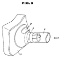
- FIG. 3 shows only the front protrusion 12 of the righthand side frame 10 and the front holder 4 joined thereto as the front protrusion of the lefthand side frame and the front holder joined thereto are identical in shape.
- the lefthand side frame 11 also has a front frustoconical protrusion 13, with a front holder 5 joined thereto.
- the front holders 4, 5 have frustoconical joint surfaces 4a, 5a complementary in shape to the front protrusions 12, 13, respectively, and fastened to outer surfaces of the front protrusions 12, 13 by rivets 30, 31, respectively.
- the rivets 30, 31 extend through the front holders 4, 5 and the outer skin layers 10b, 11b of the sandwiched structural bodies of the side frames 10, 11, and have pressed and hammered heads clamping the front holders 4, 5 and the outer skin layers 10b, 11b therebetween.
- An adhesive may also or alternatively be used to bond the front holders 4, 5 to the front protrusions 12, 13 and also the connector 6 to the front holders 4, 5.
- the front holders 4, 5 have respective tubular fitting portions 18, 19 extending rearwardly from the joint surfaces 4a, 5a, respectively.
- the front connector 6, which is of a tubular shape, has opposite ends fitted respectively over and joined to the tubular fitting portions 18, 19. Therefore, the side frames 10, 11 are coupled to each other in supporting relationship to each other by the front holders 4, 5 and the connector 6.
- the reinforced body structure shown in FIG. 2 is effective to withstand external forces applied in various directions to the motor vehicle body structure.
- the structure shown in FIG. 2 is mechanically strong enough to resist such lateral external forces because the connector 6 between the side frames 10, 11 is sufficiently rigid against compressive forces.
- the front protrusions 12, 13 and the joint surfaces 4a, 5a of the front holders 4, 5 are frustoconical in shape, when a compressive force F1 (FIG. 3) is transmitted from the connector 6 through the front holder 4 to the side frame 10, the applied force F1 is divided into a compressive force and a shearing force by the front frustoconical protrusion 12, and these divided forces are distributed over the side frame 10. Therefore, the structure shown in FIG. 2 is mechanically strong against laterally applied external forces.
- the connector 6 between the side frames 10, 11 is also rigid against external forces such as torsional or bending forces. Accordingly, the motor vehicle body is of increased rigidity against such external forces.
- the frustoconical joint surfaces 4a, 5a of the front holders 4, 5 are also effective to break and distribute torsional or bending forces, which are applied from the connector 6 and the front holders 4, 5, over the side frames 10, 11. The rigidity of the motor vehicle body is thus very high against torsional or bending stresses.
- front protrusions 12, 13, the front holders 4, 5, and the front connector 6 are described by way of example, the rear protrusions, the rear holders, and the rear connector are of the same structure and joined together in the same manner for high mechanical strength and rigidity against various external forces.
- a steering column (not shown) may be mounted on the front connector 6. Since the front connector 6 is rigid, external forces applied through the steering column to the front connector 6 are sufficiently resisted by the front connector 6, and hence the motor vehicle body is of increased rigidity against such external forces.
- the frustoconical joints between the side frames 10, 11 and the front holders 4, 5 are effective to break and distribute external forces, which are applied through the steering column to the motor vehicle body, over the side frames 10, 11 through the front connector 6 and the front holders 4, 5. The motor vehicle body therefore has increased rigidity against such external forces.
- each of the side frames 10, 11 is of a unitary structure.
- the front member 1, the middle member 2, and the rear member 3 of each of the side frames 10, 11 may be separate from each other.
- front and rear reinforced structures respectively in the boundary regions between the front pillar 21 and the front member 1 and between the rear pillar 24 and the rear member 3.
- the position and number of such reinforced structures, the configurations of their portions where components are attached, and the dimensions of such components may be determined depending on the magnitude and direction of external forces to be applied, and the degree of motor vehicle body rigidity to be achieved.
- the motor vehicle body rigidity may freely be varied by varying the dimensions of the joints between the holders and the protrusions and the joints between the holders and the connector.
- one of the paired holders may be integral with the connector, or both of the paired holders may be integral with the connector.
- the holders and the connector may be made of sheet steel or the like, but should preferably be made of synthetic resin from the standpoint of achieving reduced weight, and particularly preferably should be made of fiber-reinforced plastic.
- the rivets by which the protrusions of the side frames and the holders are fastened to each other may be effectively used as temporary fasteners until an adhesive by which the protrusions and the holders are bonded to each other is hardened, or may be effective as additional fasteners after such an adhesive is hardened.
- rivets may be used as temporary fasteners until an adhesive by which the holders and the connector are bonded to each other is hardened.
- Other fasteners than the rivets may be employed as the temporary fasteners or additional fasteners.
- a motor vehicle body structure according to another embodiment will be described below with reference to FIGS. 4 through 9.
- FIG. 4 shows a bracket 51 for installing a front suspension beam, front suspension upper arms, and an engine.
- the bracket 51 is fixed to a lower portion (shown shaded in FIG. 5) of a front member 70 of a side frame 52 in the form of a sandwiched structural body.
- the bracket 51 comprises a base plate 61 and a plurality of side plates 62a, 62b, 63a, 63b.
- the base plate 61 is fixed to an outer surface of the side frame 70, and has a joint surface 61a (see FIG. 7) complementary in shape to the outer surface of the side frame 70.
- the side plates 62a, 62b, 63a, 63b extend outwardly from the base plate 61.
- the side plates 62a, 62b jointly serve as a component attachment 62
- the side plates 63a, 63b jointly serve as another component attachment 63.
- Components may be attached to the component attachments 62, 63 by inserting pins on ends of the components into holes defined in the side plates 62a, 62b, 63a, 63b or using suitable fasteners such as bolts.
- a front suspension beam 53 is also attached to the bracket 51 by an attachment structure, described later on.
- FIG. 6 shows the component attachment 63 to an enlarged scale.
- the two side plates 63a, 63b are spaced from each other and extend parallel to each other, and project perpendicularly from the base plate 61.
- the side plates 63a, 63b have respective attachment holes 64a, 64b defined therein at confronting positions.
- the side plates 63a, 63b also have respective flanges 65a, 65b, and are interconnected and reinforced by a back plate 66.
- the component attachment 62 shown in FIG. 4 is identical in structure to the component attachment 63 shown in FIG. 6.
- bracket 51 is joined to the front member 70 of the side frame 52 shown in FIG. 5.
- the front member 70 is in the form of a sandwiched structural body comprising a core layer 73 covered with a pair of outer skin layers 71, 72.
- the outer skin layers 71, 72 have lower ends joined to each other into a flange 74.
- the joint surface 61a of the base plate 61 is snugly held against and fixed to the corresponding surface of the front member 70.
- the bracket 51 may be secured to the front member 70 by an adhesive or fasteners such as rivets, but preferably by both an adhesive and fasteners. Rivets may be applied to a portion A in FIG. 7.
- the front suspension beam 53 is installed by an attachment structure as follows:
- FIG. 8 also shows the bracket 51 which is joined to the front member 70 of the side frame 52, and illustrates an attachment structure for the front end of the front suspension beam 53.
- the front member 70 has a lower surface 75 spaced from the base plate 61 of the bracket 51 with a space S1 defined therebetween.
- the base plate 61 has a plurality of attachment holes 65 in a central area thereof, and collars 66 are mounted respectively in the attachment holes 65.
- the front suspension beam 53 is fastened to the bracket 51 by bolts or the like extending through the attachment holes 65.
- the space S1 serves to accommodate the heads of the bolts or nuts threaded over the bolts.
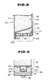
- FIG. 9 also shows the bracket 51 which is joined to the front member 70 of the side frame 52, and also illustrates an attachment structure for the rear end of the front suspension beam 53.
- a space S2 defined between a lower surface 76 of the front member 70 and the base plate 61 of the bracket 51 accommodates a bracket 77 which houses a nut therein.
- the bracket 77 has flanged ends 77a, 77b bonded to the lower surface 76 of the front member 70.
- the front suspension beam 53 is fastened to the base plate 61 by a bolt 79 and a nut 78, the nut 78 being accommodated in the bracket 77.
- the bracket 77 doubles as a spacer for keeping the front member 70 and the base plate 61 spaced from each other and also a stiffener for stiffening the front member 70 and the base plate 61.
- the nuts (for example, the nut 78 shown in FIG. 9) used to fasten the front suspension beam 53 to the bracket 51 as shown in FIGS. 8 and 9 should preferably be so-called floating nuts to facilitate the installation of the front suspension beam 53 on the bracket 51.
- the component attachments have increased mechanical strength.
- the component attachments 62, 63 used, it is not necessary to form recesses in the motor vehicle body for respective components to be installed, and hence the mechanical strength of the motor vehicle body is not lowered.
- the bracket 51 Since the base plate 61 of the bracket 51 is snugly fixed to the wide surface of the front member 70, the bracket 51 serves as a reinforcement.
- the motor vehicle body structure, incorporated in the front member 70 of the side frame 52, is effective to increase not only the mechanical strength but also the shock resistance of the motor vehicle body.
- the bracket 51 may be made of metal such as aluminum, iron, stainless steel, or the like, or synthetic resin or reinforced plastic.
- Another pair of side plates may be attached to the base plate 61 of the bracket 51, and an engine may be installed on these side plates.
- the principles of the present invention may be applied to not only the component attachments on the front member 70 of the side frame 52, but also other component attachments.
- the motor vehicle body structure allows the motor vehicle to be reduced in weight and manufactured with increased productivity, and increases the rigidity of the motor vehicle body for increased resistance to shocks induced by external forces applied in various directions and also for increased mechanical strength of component attachments.
- the present invention provides a motor vehicle body structure in the form of a sandwiched structural body mainly made of synthetic resin, the motor vehicle body structure being of higher rigidity against torsional and bending stresses; and furthermore provides a motor vehicle body structure which allows various components to be attached, such as in a front frame region, with high mechanical strength, and which increases the mechanical strength and shock resistance of a motor vehicle that incorporates the motor vehicle body structure.
Landscapes
- Engineering & Computer Science (AREA)
- Architecture (AREA)
- Structural Engineering (AREA)
- Chemical & Material Sciences (AREA)
- Combustion & Propulsion (AREA)
- Transportation (AREA)
- Mechanical Engineering (AREA)
- Body Structure For Vehicles (AREA)
Applications Claiming Priority (4)
| Application Number | Priority Date | Filing Date | Title |
|---|---|---|---|
| JP42209/90U | 1990-04-20 | ||
| JP4220990U JPH041080U (de) | 1990-04-20 | 1990-04-20 | |
| JP44404/90U | 1990-04-25 | ||
| JP4440490U JPH043876U (de) | 1990-04-25 | 1990-04-25 |
Publications (2)
| Publication Number | Publication Date |
|---|---|
| EP0453325A1 true EP0453325A1 (de) | 1991-10-23 |
| EP0453325B1 EP0453325B1 (de) | 1994-11-17 |
Family
ID=26381860
Family Applications (1)
| Application Number | Title | Priority Date | Filing Date |
|---|---|---|---|
| EP19910303592 Expired - Lifetime EP0453325B1 (de) | 1990-04-20 | 1991-04-22 | Kraftfahrzeug-Karosserie mit einer Sandwich-Struktur für den Wagenkasten |
Country Status (2)
| Country | Link |
|---|---|
| EP (1) | EP0453325B1 (de) |
| DE (1) | DE69105159T2 (de) |
Citations (3)
| Publication number | Priority date | Publication date | Assignee | Title |
|---|---|---|---|---|
| FR2360459A1 (fr) * | 1976-08-02 | 1978-03-03 | Renault | Carrosserie de vehicule automobile |
| US4559274A (en) * | 1982-04-27 | 1985-12-17 | Ford Motor Company | Composite components of sandwich construction |
| US4573707A (en) * | 1984-01-30 | 1986-03-04 | Pabst Rudolf D | Composite lightweight non-metallic vehicle frame |
-
1991
- 1991-04-22 DE DE1991605159 patent/DE69105159T2/de not_active Expired - Fee Related
- 1991-04-22 EP EP19910303592 patent/EP0453325B1/de not_active Expired - Lifetime
Patent Citations (3)
| Publication number | Priority date | Publication date | Assignee | Title |
|---|---|---|---|---|
| FR2360459A1 (fr) * | 1976-08-02 | 1978-03-03 | Renault | Carrosserie de vehicule automobile |
| US4559274A (en) * | 1982-04-27 | 1985-12-17 | Ford Motor Company | Composite components of sandwich construction |
| US4573707A (en) * | 1984-01-30 | 1986-03-04 | Pabst Rudolf D | Composite lightweight non-metallic vehicle frame |
Also Published As
| Publication number | Publication date |
|---|---|
| DE69105159T2 (de) | 1995-03-23 |
| DE69105159D1 (de) | 1994-12-22 |
| EP0453325B1 (de) | 1994-11-17 |
Similar Documents
| Publication | Publication Date | Title |
|---|---|---|
| US5150944A (en) | Joint structure for sandwiched structural body | |
| CA1297137C (en) | Vehicle frame rail assembly and underbody construction | |
| US7287797B1 (en) | Automotive vehicle having a modular plastic body attached to a metal chassis | |
| US4597601A (en) | Energy absorbing vehicle bumper | |
| US4848835A (en) | Vehicle frame rail assembly and underbody construction | |
| US5195779A (en) | Motor vehicle body structure employing sandwiched structural body | |
| US4958844A (en) | Load bearing structural member and frame structure | |
| US11161548B2 (en) | Chassis for a vehicle | |
| EP0823363B1 (de) | Karosserie-Tragstruktur für ein Fahrzeug | |
| EP0372987B1 (de) | Elementmontierungsstruktur für eine Fahrzeugkarosserie | |
| US4509782A (en) | Energy absorbing vehicle bumper | |
| US4763948A (en) | Automobile front body construction | |
| JP6358280B2 (ja) | 車体パネルの取付構造 | |
| US4715630A (en) | Energy absorbing vehicle bumper | |
| EP0453325A1 (de) | Kraftfahrzeug-Karosserie mit einer Sandwich-Struktur für den Wagenkasten | |
| JPH01103586A (ja) | 自動車の樹脂製車体構造 | |
| EP0452129B1 (de) | Verbindungsanordnung für Körper mit Sandwich-Struktur | |
| JPH0545594Y2 (de) | ||
| JPH077271Y2 (ja) | サンドイッチ構造体からなる車両ボディの部品取付構造 | |
| KR102929007B1 (ko) | 목적 기반 차량용 프레임 모듈 | |
| CN224045279U (zh) | 一种车辆支撑柱及车辆 | |
| CN223315095U (zh) | 前地板总成及车辆 | |
| JP2841062B1 (ja) | 鉄道車両用構体とその製作方法 | |
| WO2003057455A1 (en) | Method for manufacturing a chassis of composite material for a kart and chassis of composite material for a kart manufactured by such a method | |
| JP2020142632A (ja) | 車両のルーフ構造 |
Legal Events
| Date | Code | Title | Description |
|---|---|---|---|
| PUAI | Public reference made under article 153(3) epc to a published international application that has entered the european phase |
Free format text: ORIGINAL CODE: 0009012 |
|
| AK | Designated contracting states |
Kind code of ref document: A1 Designated state(s): DE FR GB |
|
| 17P | Request for examination filed |
Effective date: 19911106 |
|
| 17Q | First examination report despatched |
Effective date: 19930706 |
|
| GRAA | (expected) grant |
Free format text: ORIGINAL CODE: 0009210 |
|
| AK | Designated contracting states |
Kind code of ref document: B1 Designated state(s): DE FR GB |
|
| ET | Fr: translation filed | ||
| REF | Corresponds to: |
Ref document number: 69105159 Country of ref document: DE Date of ref document: 19941222 |
|
| PLBE | No opposition filed within time limit |
Free format text: ORIGINAL CODE: 0009261 |
|
| STAA | Information on the status of an ep patent application or granted ep patent |
Free format text: STATUS: NO OPPOSITION FILED WITHIN TIME LIMIT |
|
| 26N | No opposition filed | ||
| PGFP | Annual fee paid to national office [announced via postgrant information from national office to epo] |
Ref country code: FR Payment date: 20010409 Year of fee payment: 11 |
|
| PGFP | Annual fee paid to national office [announced via postgrant information from national office to epo] |
Ref country code: GB Payment date: 20010418 Year of fee payment: 11 Ref country code: DE Payment date: 20010418 Year of fee payment: 11 |
|
| REG | Reference to a national code |
Ref country code: GB Ref legal event code: IF02 |
|
| PG25 | Lapsed in a contracting state [announced via postgrant information from national office to epo] |
Ref country code: GB Free format text: LAPSE BECAUSE OF NON-PAYMENT OF DUE FEES Effective date: 20020422 |
|
| PG25 | Lapsed in a contracting state [announced via postgrant information from national office to epo] |
Ref country code: DE Free format text: LAPSE BECAUSE OF NON-PAYMENT OF DUE FEES Effective date: 20021101 |
|
| GBPC | Gb: european patent ceased through non-payment of renewal fee |
Effective date: 20020422 |
|
| PG25 | Lapsed in a contracting state [announced via postgrant information from national office to epo] |
Ref country code: FR Free format text: LAPSE BECAUSE OF NON-PAYMENT OF DUE FEES Effective date: 20021231 |
|
| REG | Reference to a national code |
Ref country code: FR Ref legal event code: ST |