EP0453343A1 - Pregrooved information medium with offset pits, method of making the pits, method for extracting a tracting error signal and reproducing apparatus for realizing this method - Google Patents
Pregrooved information medium with offset pits, method of making the pits, method for extracting a tracting error signal and reproducing apparatus for realizing this method Download PDFInfo
- Publication number
- EP0453343A1 EP0453343A1 EP91400858A EP91400858A EP0453343A1 EP 0453343 A1 EP0453343 A1 EP 0453343A1 EP 91400858 A EP91400858 A EP 91400858A EP 91400858 A EP91400858 A EP 91400858A EP 0453343 A1 EP0453343 A1 EP 0453343A1
- Authority
- EP
- European Patent Office
- Prior art keywords
- marks
- tracks
- signal
- offset
- etching
- Prior art date
- Legal status (The legal status is an assumption and is not a legal conclusion. Google has not performed a legal analysis and makes no representation as to the accuracy of the status listed.)
- Granted
Links
- 238000000034 method Methods 0.000 title claims description 10
- 238000004519 manufacturing process Methods 0.000 title claims description 8
- 238000005530 etching Methods 0.000 claims abstract description 35
- 230000003287 optical effect Effects 0.000 claims abstract description 23
- 238000005259 measurement Methods 0.000 claims description 10
- 238000001514 detection method Methods 0.000 claims description 6
- 238000005070 sampling Methods 0.000 claims description 3
- 230000000295 complement effect Effects 0.000 claims description 2
- 230000003247 decreasing effect Effects 0.000 claims description 2
- 238000012544 monitoring process Methods 0.000 claims 1
- 230000005855 radiation Effects 0.000 claims 1
- PCHJSUWPFVWCPO-UHFFFAOYSA-N gold Chemical compound [Au] PCHJSUWPFVWCPO-UHFFFAOYSA-N 0.000 description 2
- 239000010931 gold Substances 0.000 description 2
- 229910052737 gold Inorganic materials 0.000 description 2
- 239000003990 capacitor Substances 0.000 description 1
- 230000000694 effects Effects 0.000 description 1
- 230000003071 parasitic effect Effects 0.000 description 1
- 230000010287 polarization Effects 0.000 description 1
Images


Classifications
-
- G—PHYSICS
- G11—INFORMATION STORAGE
- G11B—INFORMATION STORAGE BASED ON RELATIVE MOVEMENT BETWEEN RECORD CARRIER AND TRANSDUCER
- G11B7/00—Recording or reproducing by optical means, e.g. recording using a thermal beam of optical radiation by modifying optical properties or the physical structure, reproducing using an optical beam at lower power by sensing optical properties; Record carriers therefor
- G11B7/24—Record carriers characterised by shape, structure or physical properties, or by the selection of the material
- G11B7/2407—Tracks or pits; Shape, structure or physical properties thereof
- G11B7/24085—Pits
-
- G—PHYSICS
- G11—INFORMATION STORAGE
- G11B—INFORMATION STORAGE BASED ON RELATIVE MOVEMENT BETWEEN RECORD CARRIER AND TRANSDUCER
- G11B7/00—Recording or reproducing by optical means, e.g. recording using a thermal beam of optical radiation by modifying optical properties or the physical structure, reproducing using an optical beam at lower power by sensing optical properties; Record carriers therefor
- G11B7/08—Disposition or mounting of heads or light sources relatively to record carriers
- G11B7/09—Disposition or mounting of heads or light sources relatively to record carriers with provision for moving the light beam or focus plane for the purpose of maintaining alignment of the light beam relative to the record carrier during transducing operation, e.g. to compensate for surface irregularities of the latter or for track following
- G11B7/0938—Disposition or mounting of heads or light sources relatively to record carriers with provision for moving the light beam or focus plane for the purpose of maintaining alignment of the light beam relative to the record carrier during transducing operation, e.g. to compensate for surface irregularities of the latter or for track following servo format, e.g. guide tracks, pilot signals
-
- G—PHYSICS
- G11—INFORMATION STORAGE
- G11B—INFORMATION STORAGE BASED ON RELATIVE MOVEMENT BETWEEN RECORD CARRIER AND TRANSDUCER
- G11B7/00—Recording or reproducing by optical means, e.g. recording using a thermal beam of optical radiation by modifying optical properties or the physical structure, reproducing using an optical beam at lower power by sensing optical properties; Record carriers therefor
- G11B7/24—Record carriers characterised by shape, structure or physical properties, or by the selection of the material
- G11B7/26—Apparatus or processes specially adapted for the manufacture of record carriers
Definitions
- the present invention relates to an information medium intended for recording, along tracks, optically readable information, more particularly an information medium comprising pre-etchings comprising at least offset marks embodying the mean axis of the tracks. along which optically readable information can be saved.
- the present invention also relates to a method of making marks offset relative to the mean axis of the tracks as well as a method of producing an error signal for radial tracking of a track when reading a such an information medium and an optical reading device for the implementation of the method for producing the error signal for radial tracking of tracks.
- the disc has angular zones 4 reserved for recording user information as represented by the marks 10 centered on the axes and pre-engraving zones 5 reserved for the service functions of the disc such as the enslavement of the optical beam on the runway, focusing, synchronization, access. Zones 4 and 5 are made so as to be, at least locally, aligned radially.
- the pre-etching zones 5 each comprise at least two successive marks 23 and 33 offset on each side of the mean axis of the tracks 1a, 1b, 1c. These marks are used to perform the radial tracking of the runway.
- the same offset mark is used associated with two contiguous axes.
- the mark 33 centered at E is used to carry out the radial tracking of the axis 1a and of the axis 1b.
- the mark 23 centered in D is used to perform the radial tracking of the axis 1b and the axis 1c.
- two separate marks symbolized by the dashed lines have therefore been replaced by a single mark centered midway between the tracks which it must materialize. Marks 23 and 33 therefore appear to consist of two partially superimposed marks.
- the object of the present invention is to remedy this drawback by proposing to use in each pre-etching zone only one offset mark on the two used until now.
- the information written on an information medium as described above is read by detecting the light diffracted by the information medium and re-entering the objective generating the optical spot which illuminates the medium as is well known to those skilled in the art.
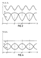
- the diffracted light is detected by photodetectors which transform the light signal into an electrical signal. If the light spot T is displaced in the direction symbolized by the arrow C in FIG. 1, at the lines AA and BB which cross the pre-etching marks 23 and 33 respectively in the center C, D and E, F of these pre-engraving marks, the curves V A and V B shown in FIG. 2 are respectively obtained.
- the abscissa Or represents the distance to the center of the disc.
- the object of the present invention is to provide a new pre-engraved information carrier with offset marks, the structure of the marks making it possible to obtain a curve V S parallel to the axis Gold.
- the subject of the present invention is an information medium comprising at least one face intended for recording, along tracks, optically readable information, the medium being provided with pre-engraving zones alternating with zones intended for recording of said information, the pre-etching zones comprising discrete patterns materializing the mean axis of the tracks, characterized in that, in each pre-etching zone, the discrete patterns are constituted by marks centered midway between two adjacent tracks and having an optical width, as provided by an actual optic with a limited transfer function, in the direction perpendicular to the axis of the tracks, substantially equal to the optical width of the zone located between two successive marks in said direction and in this that, from one pre-engraving zone to the next, the marks have equal offsets and opposite signs with respect to the central axes yen tracks.
- the present invention also relates to a method for producing marks offset relative to the mean axis of the tracks on an information medium as defined above.
- the marks deported on one side are engraved by deflection of the etching beam when passing over a first track and the marks deported on the other side by deflection of the engraving beam during the passage on a second track adjacent to the first track and then repeating the above operation until the end of the etching of the father support.
- the marks offset by deflection of the etching beam are engraved alternately on one side and the other of the mean axis of the tracks, a first part of the mark being engraved during the passage of the beam on a first track and a second part of the axially complementary mark being engraved during the passage of the beam on a second track adjacent to the first track.
- the present invention also relates to a method for producing an error signal for radial tracking of a track by a light spot for exploring the tracks of an information medium as described above, in which at least once carries out the sum of the signals detected by optical detection means during the passage of the light spot on two remote marks respectively on one side and the other and this sum is memorized, then one elaborates the radial track tracking error signal by alternately subtracting said sum from the signal detected during the passage of the light spot on one of the offset marks and the signal detected during the passage of the light spot on the other offset mark at said sum.
- the pre-etching zones 5 have a single mark offset, namely the marks 23 ′ for the pre-etching area 5 A , and the marks 33 ′ for the pre-etching area 5 B.
- the offset pre-etching marks 23 ′ and 33 ′ are chosen to have the same radial optical dimension r as the radial area r ′ situated between these same marks.
- the marks are centered exactly halfway between the tracks between which they are located, as symbolized by the references C′-D ′ and E′-F ′, which represent the center of said offset marks, respectively 23 ′ and 33 ′.
- the offset marks have equal offsets and opposite signs with respect to the mean axes of the tracks as represented by the mark 23 ′ centered in C ′ and mark 33 ′ centered in E ′ with respect to axis 1a or mark 23′centered in D ′ and mark 33 ′ centered in E ′ with respect to axis 1b.
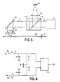
- This information carrier is used in a device for reading and recording optical discs as shown diagrammatically in FIG. 5.
- This device is composed of a laser module 51 providing a cylindrical light beam represented by the arrows f , of a cube polarization splitter 52 and a quarter-wave plate 53, a deflection mirror 54 serving for the tracking of track deviation, an objective 55 making it possible to focus the beam f on the disc and the disc 56 with axis 57.
- the beam f arriving on the disk is denoted II and the beam diffracted by the disk DD.
- the part of the beam DD which again enters the objective 55 meets the mirror 54 then the blade 53.
- This part f ′ of beam is then returned by the cube 52 to the lens 57 and to a photodetector device 58 which allows the measurement of part f ′ of the DD beam returning to objective 55.
- V S ′ results from the fact that the marks 23 ′ and 33 ′ are of the same radial optical dimension as the radial zone situated between two marks 23 ′ or two marks 33 ′ and that they are centered exactly midway between the tracks between which they are situated as represented by the references C ′, E ′, D ′, F ′ on the axis O′r ′ which correspond to the position of the centers of the offset marks represented in FIG. 3.
- this does not mean that the radial optical dimension of the marks 23 ′ or of the marks 33 ′ is equal to that of the radial zone situated between two marks 23 ′ or two marks 33 ′ when observed with an optic of infinite transfer function and therefore that these marks and these zones have the same geometric dimension.
- V S ′ V A ′ + V B ′ depends on the local properties of the disc and can vary. However, experience shows that this signal varies slowly and that even if it is necessary to know the signal V S ′ it must be determined at a lower frequency than the signal V A ′ or that the signal V B ′ , which allows to keep only one mark shifted by pre-etching areas 5.
- this device consists of sampler-blockers symbolized by the capacitors 91, 92, 93 and by switches I1, I2, I3, I4 controlling their inputs.
- the signals from the sample-and-hold units are used to supply a subtractor 94 having two high impedance inputs.
- the switches I1 and I3 are controlled by a signal d while the switches I2 and I4 are controlled by a signal g .
- the signal d is active and closes the switches I1 and I3 for a limited time less than the duration of passage of the offset mark 23 ′ when one is on the same radius of the disc as this mark 23 ′ and it is inactive the rest of the time .
- the signal g is active and closes the switches I2 and I4 for an unlimited time less than the duration of passage of the offset mark 33 ′ when one is on the same radius of the disc as this mark 33 ′.
- the upper channel 100 of the device is supplied by the signal V A ′ from the photodetector, while the lower channel 101 is supplied by the signal V B ′ also from the photodetector.
- capacities 91 and 92 are equal to c and much smaller than the capacity 93 itself equals C. A ratio of 10 between these capacities is a reasonable value.
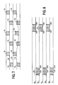
- the offset marks 24 or 34 located between tracks 1a and 1b or 1b and 1c are engraved in one go by deflection of the etching beam during its passage over one of the tracks.
- the marks 34 located between the tracks 1a and 1b are etched by deflection of the etching beam during its passage on the track 1b while the marks 24 located between the tracks 1b and 1c are etched all at once by deflection of the beam engraving during its passage on runway 1c.
- the marks 24 are therefore attached to the track 1c and the marks 34 to the track 1b. These two marks are used to control the light spot on track 1b.
- This embodiment of the offset marks can have drawbacks, in particular when a track has undergone locally, during its recording and for a fairly short duration, a deflection due to parasitic phenomena as has been represented in FIG. 7 for the track 1c.
- the deviation from track 1c which has been deliberately exaggerated in order to make it visible, introduces an error in the distance between tracks 1b and 1c and consequently the mark 24 associated with track 1c is moved relative to the track 1b.
- this mark 24 is associated with the mark 34, it creates an erroneous track error signal.
- the offset marks 23 and 33 are each made in two parts referenced 231 and 232 or 331 and 332.
- the offset marks are engraved using two successive passages of the beam of engraving.
- the mark 231 can be etched by deflecting the etching beam on the right then the mark 331 will be etched by deflecting the etching beam on the left.
- the reading beam is slaved to track 1b, we will burn part 232 by deflecting the reading beam on the left and part 332 of the mark 33 provided between tracks 1b and 1c by deflecting the reading beam on the right and so on for all brands.
- an error signal V A ′ is generated by summing the two signals V A′1 and V A′2 originating from the sampling respectively of the half-mark 231 and of the half-mark 232.
- the signal V B ′ is generated by summing the two signals V B′1 and V B′2 originating from the sampling of the half-mark respectively mark 331 and half mark 332. It is thus possible at any time to average the effect of variation of the center distance of the runway. This can have advantages insofar as the engraving of two half-marks one after the other can produce a more satisfactory result when the disc -father is burned than the superimposition over their entire length of two marks .
Landscapes
- Engineering & Computer Science (AREA)
- Manufacturing & Machinery (AREA)
- Optical Recording Or Reproduction (AREA)
Abstract
Description
La présente invention concerne un support d'informations destiné à l'enregistrement, le long de pistes, d'informations lisibles optiquement, plus particulièrement un support d'informations comportant des prégravures comprenant au moins des marques déportées matérialisant l'axe moyen des pistes le long desquelles les informations lisibles optiquement peuvent être enregistrées. La présente invention concerne aussi un procédé de réalisation des marques déportées par rapport à l'axe moyen des pistes ainsi qu'un procédé d'élaboration d'un signal d'erreur de suivi radial d'une piste lors de la lecture d'un tel support d'informations et un dispositif de lecture optique pour la mise en oeuvre du procédé d'élaboration du signal d'erreur de suivi radial de pistes.The present invention relates to an information medium intended for recording, along tracks, optically readable information, more particularly an information medium comprising pre-etchings comprising at least offset marks embodying the mean axis of the tracks. along which optically readable information can be saved. The present invention also relates to a method of making marks offset relative to the mean axis of the tracks as well as a method of producing an error signal for radial tracking of a track when reading a such an information medium and an optical reading device for the implementation of the method for producing the error signal for radial tracking of tracks.
Il a été décrit, notamment dans le brevet français N°2 523 347 au nom de THOMSON-CSF, un support d'informations mobile prégravé comportant des zones de prégravure avec notamment deux marques décalées latéralement de chaque côté de l'axe moyen de la piste pour générer un signal d'erreur d'écarts de piste et réaliser ainsi le suivi radial de la piste. Ce type de prégravure est actuellement utilisé sur certains disques optiques numériques. Toutefois, le pas interpiste doit permettre la gravure des marques décalées, ce qui limite la capacité du disque et est particulièrement pénalisant pour les disques de petit diamètre. Pour pouvoir resserrer le pas des pistes jusqu'à la limite admissible pour la diaphotie apparaissant entre les signaux d'informations enregistrés sur des pistes contigues, la société Alcatel Thomson Gigadisc a proposé, dans la demande de brevet européen N°0201093, de réaliser les marques décalées respectivement à gauche et à droite de l'axe moyen des pistes de telle sorte qu'elles présentent une disposition symétrique par rapport à l'axe d'interpiste situé à mi-distance des axes de deux éléments de piste voisins. Une telle configuration est représentée sur la figure 1. Sur cette figure, on a représenté une partie très limitée d'un disque optique classique. De ce fait, les axes des pistes 1a, 1b, 1c sont représentés symboliquement par des lignes droites tiretées, alors qu'ils sont en fait constitués par des arcs de cercle ou de spirale. D'autre part, de manière connue, le disque comporte des zones angulaires 4 réservées à l'enregistrement des informations-utilisateur telles que représentées par les marques 10 centrées sur les axes et des zones de prégravure 5 réservées aux fonctions de service du disque tels que l'asservissement du faisceau optique sur la piste, la focalisation, la synchronisation, l'accès. Les zones 4 et 5 sont réalisées de manière à être, au moins localement, alignées radialement.It has been described, in particular in French patent No. 2,523,347 in the name of THOMSON-CSF, a pre-etched mobile information medium comprising pre-etched areas with in particular two marks offset laterally on each side of the mean axis of the runway to generate a runway deviation error signal and thus carry out the radial tracking of the runway. This type of pre-engraving is currently used on certain digital optical discs. However, the step between tracks must allow the engraving of the offset marks, which limits the capacity of the disc and is particularly disadvantageous for discs of small diameter. To be able to tighten the pitch of the tracks to the admissible limit for the crosstalk appearing between the information signals recorded on contiguous tracks, the company Alcatel Thomson Gigadisc proposed, in the European patent application N ° 0201093, to carry out the shifted marks respectively to the left and to the right of the middle axis of the tracks so that they have a symmetrical arrangement with respect to the inter-track axis located halfway between the axes of two neighboring track elements. Such a configuration is shown in Figure 1. In this figure, there is shown a very limited part of a conventional optical disc. Therefore, the axes of
Comme représenté sur la figure 1, les zones de prégravure 5 comportent chacune au moins deux marques successives 23 et 33 décalées de chaque côté de l'axe moyen des pistes 1a, 1b, 1c. Ces marques sont utilisées pour réaliser le suivi radial de la piste. Pour pouvoir resserrer les axes des pistes entre eux, on utilise dans le cas de la figure 1 une même marque décalée associée à deux axes contigüs. Ainsi la marque 33 centrée en E est utilisée pour réaliser le suivi radial de l'axe 1a et de l'axe 1b. De même, la marque 23 centrée en D est utilisée pour réaliser le suivi radial de l'axe 1b et de l'axe 1c. Dans le cas de la figure 1, on a donc remplacé deux marques distinctes symbolisées par les tiretés en une marque unique centrée à mi-distance des pistes qu'elle doit matérialiser. Les marques 23 et 33 apparaisent donc formées de deux marques partiellement superposées.As shown in FIG. 1, the
Si l'utilisation de telles marques décalées de chaque côté de l'axe moyen des pistes permet de resserrer le pas des pistes, elle ne permet pas de diminuer la longueur des zones de prégravure. Or, la présente invention a pour but de remédier à cet inconvénient en proposant de n'utiliser dans chaque zone de prégravure qu'une marque décalée sur les deux utilisées jusqu'à maintenant.If the use of such marks offset on each side of the mean axis of the tracks makes it possible to narrow the pitch of the tracks, it does not make it possible to reduce the length of the pre-engraving. However, the object of the present invention is to remedy this drawback by proposing to use in each pre-etching zone only one offset mark on the two used until now.
En effet, les informations inscrites sur un support d'informations tel que décrit ci-dessus sont lues en détectant la lumière diffractée par le support d'informations et rentrant à nouveau dans l'objectif générant la tache optique qui éclaire le support comme cela est bien connu de l'homme de l'art. La lumière diffractée est détectée par des photodétecteurs qui transforment le signal lumineux en un signal électrique. Si l'on déplace la tache lumineuse T selon la direction symbolisée par la flèche C sur la figure 1, au niveau des droites AA et BB qui traversent les marques de prégravure 23 et 33 respectivement au centre C, D et E, F de ces marques de prégravure, on obtient respectivement les courbes VA et VB représentées sur la figure 2. Sur cette figure 2, l'abscisse Or représente la distance au centre du disque. Les distances correspondant aux points C et D sur la droite AA de la figure 1 sont représentées par les lettres C et D sur l'axe Or tandis que les distances correspondant aux points E et F de la droite BB sur la figure 1 sont représentées par les lettres E et F sur le même axe Or. Les différences de distances de C et de D, de D et de E, de E et de F au centre du disque sont égales entre elles et égales à l'entraxe des pistes. D'autre part, sur la figure 2 on a représenté une troisième courbe VS qui est la somme de VA et VB. Ainsi, dans le cas d'un support d'informations comportant des zones de prégravure 5 telles que représentées sur la figure 1, la courbe VS de la figure 6 est profondément modulée. Toutefois, la Demanderesse s'est aperçue que, si les deux courbes VA et VB sont rigoureusement symétriques l'une de l'autre par rapport à une droite parallèle à l'axe Or et représentant la valeur moyenne de chacune d'elle, alors la somme des deux courbes VA et VB est alors une droite parallèle à l'axe Or.Indeed, the information written on an information medium as described above is read by detecting the light diffracted by the information medium and re-entering the objective generating the optical spot which illuminates the medium as is well known to those skilled in the art. The diffracted light is detected by photodetectors which transform the light signal into an electrical signal. If the light spot T is displaced in the direction symbolized by the arrow C in FIG. 1, at the lines AA and BB which cross the
La présente invention a pour but de fournir un nouveau support d'informations prégravé à marques déportées dont la structure des marqués permet d'obtenir une courbe VS parallèle à l'axe Or.The object of the present invention is to provide a new pre-engraved information carrier with offset marks, the structure of the marks making it possible to obtain a curve V S parallel to the axis Gold.
En conséquence, la présente invention a pour objet un support d'informations comportant au moins une face destinée à l'enregistrement, le long de pistes, d'informations lisibles optiquement, le support étant muni de zones de prégravure alternant avec des zones destinées à l'enregistrement desdites informations, les zones de prégravure comportant des motifs discrets matérialisant l'axe moyen des pistes, caractérisé en ce que, dans chaque zone de prégravure, les motifs discrets sont constitués par des marques centrées à mi-distance entre deux pistes adjacentes et présentant une largeur optique, telle que fournie par une optique réelle de fonction de transfert limitée, dans le sens perpendiculaire à l'axe des pistes, sensiblement égale à la largeur optique de la zone située entre deux marques successives selon ledit sens et en ce que, d'une zone de prégravure à la suivante, les marques présentent des déports égaux et de signes contraires par rapport aux axes moyens des pistes.Consequently, the subject of the present invention is an information medium comprising at least one face intended for recording, along tracks, optically readable information, the medium being provided with pre-engraving zones alternating with zones intended for recording of said information, the pre-etching zones comprising discrete patterns materializing the mean axis of the tracks, characterized in that, in each pre-etching zone, the discrete patterns are constituted by marks centered midway between two adjacent tracks and having an optical width, as provided by an actual optic with a limited transfer function, in the direction perpendicular to the axis of the tracks, substantially equal to the optical width of the zone located between two successive marks in said direction and in this that, from one pre-engraving zone to the next, the marks have equal offsets and opposite signs with respect to the central axes yen tracks.
Ainsi, en utilisant cette configuration spécifique pour les marques déportées de la zone de prégravure du support d'informations, le signal VS = VA + VB correspondant à la somme des signaux détectés lors du passage sur les marques décalées est une constante. En conséquence, si l'on connait le signal VS une fois pour toute, il suffit de mesurer VA ou VB pour obtenir le signal d'erreur. En effet, le signal d'erreur est donné par la différence VA - VB qui dans ce cas devient égal à : e = VA - (VS - VA) = 2 VA - VS. On obtiendrait la même chose en ne gardant que les autres marques décalées 33 ; dans ce cas, le signal d'erreur e = VS - 2 VB.Thus, by using this specific configuration for the marks offset from the pre-engraving area of the information medium, the signal V S = V A + V B corresponding to the sum of the signals detected during the passage over the offset marks is a constant. Consequently, if we know the signal V S once and for all, it suffices to measure V A or V B to obtain the error signal. Indeed, the error signal is given by the difference V A - V B which in this case becomes equal to: e = V A - (V S - V A ) = 2 V A - V S. We would obtain the same thing by keeping only the
La présente invention concerne aussi un procédé de réalisation de marques déportées par rapport à l'axe moyen des pistes sur un support d'informations tel que défini ci-dessus.The present invention also relates to a method for producing marks offset relative to the mean axis of the tracks on an information medium as defined above.
Dans ce cas, lors de la réalisation d'un support-père, on grave les marques déportées d'un premier côté par déflexion du faisceau de gravure lors du passage sur une première piste et les marques déportées de l'autre côté par déflexion du faisceau de gravure lors du passage sur une seconde piste adjacente à la première piste puis l'on répète l'opération ci-dessus jusqu'à la fin de la gravure du support-père.In this case, during the production of a father support, the marks deported on one side are engraved by deflection of the etching beam when passing over a first track and the marks deported on the other side by deflection of the engraving beam during the passage on a second track adjacent to the first track and then repeating the above operation until the end of the etching of the father support.
Selon un autre mode de réalisation, lors de la réalisation d'un support-père, on grave les marques déportées par deflexion du faisceau de gravure alternativement d'un côté et de l'autre de l'axe moyen des pistes, une première partie de la marque étant gravée lors du passage du faisceau sur une première piste et une seconde partie de la marque axialement complèmentaire étant gravée lors du passage du faisceau sur une seconde piste adjacente à la première piste.According to another embodiment, during the production of a father support, the marks offset by deflection of the etching beam are engraved alternately on one side and the other of the mean axis of the tracks, a first part of the mark being engraved during the passage of the beam on a first track and a second part of the axially complementary mark being engraved during the passage of the beam on a second track adjacent to the first track.
La présente invention concerne aussi un procédé d'élaboration d'un signal d'erreur de suivi radial d'une piste par une tache lumineuse d'exploration des pistes d'un support d'informations tel que décrit ci-dessus, dans lequel on réalise au moins une fois la somme des signaux détectés par des moyens de détection optiques lors du passage de la tache lumineuse sur deux marques déportées respectivement d'un côté et de l'autre et l'on mémorise cette somme, puis l'on élabore le signal d'erreur de suivi radial de piste en soustrayant alternativement ladite somme au signal détecté lors du passage de la tache lumineuse sur l'une des marques décalées et le signal détecté lors du passage de la tache lumineuse sur l'autre marque décalée à ladite somme.The present invention also relates to a method for producing an error signal for radial tracking of a track by a light spot for exploring the tracks of an information medium as described above, in which at least once carries out the sum of the signals detected by optical detection means during the passage of the light spot on two remote marks respectively on one side and the other and this sum is memorized, then one elaborates the radial track tracking error signal by alternately subtracting said sum from the signal detected during the passage of the light spot on one of the offset marks and the signal detected during the passage of the light spot on the other offset mark at said sum.
D'autres caractéristiques et avantages de la présente invention apparaitront à la lecture de la description faite ci-après d'un mode de réalisation préférentiel du support d'informations prégravé à marques déportées ainsi que d'un mode de réalisation d'un dispositif de lecture permettant de lire le support d'informations prégravé et d'obtenir un signal d'erreur de suivi radial, cette description étant faite avec référence aux dessins ci-annexés dans lesquels:
- la figure 1 déjà décrite représente schématiquement une partie d'un support d'informations prégravé à marques déportées conforme à l'art antérieur ;
- la figure 2 déjà décrite est une courbe donnant l'amplitude des signaux électriques détectés lors du passage sur les marques en fonction de leur distance au centre du disque ;
- la figure 3 est une représentation schématique d'un support d'informations prégravé à marques déportées conforme à la présente invention ;
- la figure 4 représente les courbes donnant l'amplitude des signaux détectés lors du passage sur les marques déportées en fonction de leur distance au centre du support ;
- la figure 5 est une représentation schématique d'un dispositif de lecture optique utilisé avec un support d'informations prégravé cconforme à la présente invention ;
- la figure 6 est une représentation schématique d'un circuit donnant le signal d'erreur de suivi de piste ;
- les figures 7 et 8 sont deux représentations schématiques d'un support d'informations prégravé à marques déportées conforme à la présente invention expliquant différents procédés de réalisation des marques.
- Figure 1 already described schematically shows part of a pre-engraved information carrier with offset marks according to the prior art;
- FIG. 2 already described is a curve giving the amplitude of the electrical signals detected during the passage over the marks as a function of their distance from the center of the disc;
- FIG. 3 is a schematic representation of a pre-engraved information carrier with offset marks according to the present invention;
- FIG. 4 represents the curves giving the amplitude of the signals detected when passing over the offset marks as a function of their distance from the center of the support;
- FIG. 5 is a schematic representation of an optical reading device used with a pre-engraved information medium conforming to the present invention;
- FIG. 6 is a schematic representation of a circuit giving the tracking error signal;
- Figures 7 and 8 are two schematic representations of a pre-engraved information carrier with offset marks according to the present invention explaining different methods of making the marks.
Pour simplifier la description, dans les figures les mêmes éléments portent les mêmes références.To simplify the description, in the figures the same elements have the same references.
D'autre part, la présente invention a été décrite en se référant à des marques de prégravure de forme oblongue. Toutefois, il est évident pour l'homme de l'art que d'autres types de marques de prégravure peuvent être utilisés, notamment des marques circulaires.On the other hand, the present invention has been described with reference to oblong shaped pre-engraving marks. However, it is obvious to a person skilled in the art that other types of pre-etching marks can be used, in particular circular marks.
Conformément à la présente invention et comme représenté sur la figure 3, qui représente schématiquement une portion d'un disque optique numérique comportant des axes de piste symbolisés par les références 1a, 1b, 1c, selon lesquels seront enregistrées des informations-utilisateurs 10 dans des zones 4, les zones de prégravure 5 comportent une seule marque décalée, à savoir les marques 23′ pour la zone de prégravure 5A, et les marques 33′ pour la zone de prégravure 5B. Conformément à la présente invention, les marques de prégravure 23′ et 33′ décalées sont choisies de même dimension optique radiale r que la zone radiale r′ située entre ces mêmes marques. D'autres part, les marques sont centrées exactement à mi-distance des pistes entre lesquelles elles sont situées, comme symbolisé par les références C′-D′ et E′-F′, qui représentent le centre desdites marques décalées, respectivement 23′ et 33′. D'autre part, conformément à la présente invention, d'une zone de prégravure 5A à la zone de prégravure suivante 5B, les marques décalées présentent des déports égaux et de signes contraires par rapport aux axes moyens des pistes comme représentés par la marque 23′ centrée en C′ et la marque 33′ centrée en E′ par rapport à l'axe 1a ou la marque 23′centrée en D′ et la marque 33′ centrée en E′ par rapport à l'axe 1b.In accordance with the present invention and as shown in FIG. 3, which schematically represents a portion of a digital optical disc comprising track axes symbolized by the
Ce support d'informations est utilisé dans un dispositif lecteur-enregistreur de disques optiques tel que représenté schématiquement sur la figure 5. Ce dispositif est composé d'un module laser 51 fournissant un faisceau lumineux cylindrique représenté par les flèches f, d'un cube séparateur de polarisation 52 et d'une lame quart d'onde 53, d'un miroir de renvoi 54 servant à l'asservissement d'écart de piste, d'un objectif 55 permettant de focaliser le faisceau f sur le disque et le disque 56 d'axe 57. Le faisceau f arrivant sur le disque est noté I-I et le faisceau diffracté par le disque D-D. La partie du faisceau D-D qui pénètre à nouveau dans l'objectif 55 rencontre le miroir 54 puis la lame 53. Cette partie f′ de faisceau est ensuite renvoyée par le cube 52 vers la lentille 57 et vers un dispositif photodétecteur 58 qui permet la mesure de la partie f′ du faisceau D-D retournant dans l'objectif 55.This information carrier is used in a device for reading and recording optical discs as shown diagrammatically in FIG. 5. This device is composed of a
Si l'on examine la lumière rentrant à nouveau dans l'objectif 55 quand la tache lumineuse T se déplace selon la direction C sur la figure 3 et occupe différentes positions successives sur les droites A′A′ et B′B′ de la figure 3, on obtient en sortie du photodétecteur 58 respectivement les courbes VA′ et VB′ représentées sur la figure 4.If we examine the
Dans ce cas, on voit que les courbes VA′ et VB′ sont rigoureusement symétriques l'une de l'autre par rapport à une droite parallèle à l'axe O′r′. De ce fait, lorsque l'on réalise la somme des signaux VA′ et VB′, on obtient la courbe VS′ qui est formée par une droite parallèle à l'axe O′r′. Cette invariance de VS′ résulte du fait que les marques 23′ et 33′ sont de même dimension optique radiale que la zone radiale située entre deux marques 23′ ou deux marques 33′ et qu'elles sont centrées exactement à mi-distance des pistes entre lesquelles elles sont situées comme représenté par les références C′, E′, D′, F′ sur l'axe O′r′ qui correspondent à la position des centres des marques décalées représentées sur la figure 3. En fait, cela ne signifie pas que la dimension optique radiale des marques 23′ ou des marques 33′ soit égale à celle de la zone radiale située entre deux marques 23′ ou deux marques 33′ quand on les observe avec une optique de fonction de transfert infinie et donc que ces marques et ces zones ont même dimension géométrique. Il suffit que les signaux de lecture, obtenus par l'emploi d'une optique réelle et donc de fonction de transfert optique limitée, aient les propriétés de symétrie de ceux de la figure 4. Des marques 23 et 33 décrites dans la figure 1 peuvent donner, avec une optique de fonction de transfert limitée, des signaux similaires à ceux de la figure 4. Il est certain que plus les dimensions géométriques radiales des marques 23′et 33′ sont proches de celles des zones qui séparent deux marques 23′ ou deux marques 33′, plus la condition des signaux de la figure 4 est bien vérifiée ; mais l'expérience prouve que malgré une différence notable dans ces deux dimensions radiales, il est possible d'obtenir des signaux proches de ceux de la figure 4 et fournissant un asservissement très satisfaisant.In this case, we see that the curves V A ′ and V B ′ are rigorously symmetrical to each other with respect to a straight line parallel to the axis O′r ′. Therefore, when we realize the sum of the signals V A ′ and V B ′ , we obtain the curve V S ′ which is formed by a straight line parallel to the axis O′r ′. This invariance of V S ′ results from the fact that the
Il est possible en utilisant les marques décalées de la figure 3 de réaliser le suivi radial de piste. En effet, le signal d'erreur e = VA′ - VB′ et ce signal d'erreur alimente un dispositif permettant de déplacer radialement la tache lumineuse sur le disque. Lorsque l'on utilise un support d'informations du type représenté à la figure 3, si l'on calcule le signal d'erreur e pour les marques 23′, on obtient e = VA′ - (VS′- VA′) = 2 VA′ - VS′ puisque VS′ est une constante. De la même façon, lorsque l'on arrive au niveau des marques décalées 33′, e = VS′ - 2 VB′. En fait, VS′= VA′ + VB′ dépend des propriétés locales du disque et peut varier. Toutefois, l'expérience montre que ce signal varie lentement et que même si il est nécessaire de connaître le signal VS′celui-ci doit être déterminé à une fréquence plus basse que le signal VA′ou que le signal VB′, ce qui permet de ne conserver qu'une seule marque décalée par zones de prégravure 5.It is possible by using the offset marks of FIG. 3 to carry out the radial track tracking. Indeed, the error signal e = V A ′ - V B ′ and this error signal supplies a device making it possible to radially move the light spot on the disc. When using an information medium of the type shown in FIG. 3, if we calculate the error signal e for the
On décrira maintenant avec référence à la figure 6 un dispositif permettant de calculer le signal d'erreur. Comme représenté sur la figure 6, ce dispositif est constitué par des échantillonneurs-bloqueurs symbolisés par les capacités 91, 92, 93 et par des interrupteurs I₁, I₂, I₃, I₄ commandant leurs entrées. Les signaux issus des échantillonneurs-bloqueurs sont utilisés pour alimenter un soustracteur 94 possèdant deux entrées à haute impédance. Les interrupteurs I₁ et I₃ sont commandés par un signal d tandis que les interrupteurs I₂ et I₄ sont commandés par un signal g. Le signal d est actif et ferme les interrupteurs I₁ et I₃ pendant un temps limité inférieur à la durée de passage de la marque décalée 23′ quand on est sur le même rayon du disque que cette marque 23′ et il est inactif le reste du temps. Le signal g est actif et ferme les interrupteurs I₂ et I₄ pendant un temps illimité inférieur à la durée de passage de la marque décalée 33′ quand on est sur le même rayon du disque que cette marque 33′. Comme représenté sur la figure 6, la voie supérieure 100 du dispositif est alimentée par le signal VA′ issu du photodétecteur, tandis que la voie inférieure 101 est alimentée par le signal VB′ issu aussi du photodétecteur. D'autre part, les capacités 91 et 92 sont égales à c et beaucoup plus petites que la capacité 93 égale elle-même à C. Un rapport de 10 entre ces capacités est une valeur raisonnable. En régime établi, la sortie du dispositif de la figure 6 fournit tour à tour les valeurs VA′ - 1/2 VS′, 1/2 VS′- VB′, VA′ - 1/2 VS′, et ainsi de suite, soit 1/2 e. En effet, VS′ représente la moyenne de VS′ pondérée sur tous les échantillons mesurés suivant une suite géométrique décroissante. A savoir VS′ = VA′n + αVB′n + α²VA′n - 1 + α³ VB′n - 1 + ...We will now describe with reference to Figure 6 a device for calculating the error signal. As shown in FIG. 6, this device consists of sampler-blockers symbolized by the
En décrira maintenant, avec référence aux figures 7 et 8, différents procédés de réalisation des marques décalées conforme à la présente invention.Now describe, with reference to Figures 7 and 8, different methods of making offset marks according to the present invention.
Dans le cas de la figure 7, les marques décalées 24 ou 34 situées entre les pistes 1a et 1b ou 1b et 1c sont gravées en une seule fois par déflexion du faisceau de gravure lors de son passage sur une des pistes. Ainsi, les marques 34 situées entre les pistes 1a et 1b sont gravées par déflexion du faisceau de gravure lors de son passage sur la piste 1b tandis que les marques 24 situées entre les pistes 1b et 1c sont gravées en une seule fois par déflexion du faisceau de gravure lors de son passage sur la piste 1c. Les marques 24 sont donc attachées à la piste 1c et les marques 34 à la piste 1b. Ces deux marques sont utilisées pour asservir la tache lumineuse sur la piste 1b. Ce mode de réalisation des marques décalées peut présenter des inconvénients, notamment lorsqu'une piste a subi localement, lors de son enregistrement et pendant une durée assez courte, une déflexion due à des phénomènes parasites comme cela a été représenté sur la figure 7 pour la piste 1c. Dans ce cas, la déviation de la piste 1c qui a été volontairement exagérée afin de la rendre visible, introduit une erreur dans l'entraxe des pistes 1b et 1c et par suite la marque 24 associée à la piste 1c est déplacée par rapport à la piste 1b. Quand cette marque 24 est associée à la marque 34, elle crée un signal d'erreur de piste erronée.In the case of FIG. 7, the offset marks 24 or 34 located between
Pour remédier à cet inconvénient, on peut graver les marques décalées comme symbolisées sur la figure 8. Dans ce cas, les marques décalées 23 et 33 sont réalisées chacune en deux parties référencées 231 et 232 ou 331 et 332. Dans ce cas, les marques décalées sont gravées en utilisant deux passages successifs du faisceau de gravure. Ainsi, lorsque le faisceau de gravure suit l'axe la la marque 231 peut être gravée en défléchissant le faisceau de gravure à droite puis la marque 331 sera gravée en défléchissant le faisceau de gravure à gauche. Ensuite, lorsque le faisceau de lecture sera asservi à la piste 1b, on gravera la partie 232 en défléchissant le faisceau de lecture à gauche et la partie 332 de la marque 33 prévue entre les pistes 1b et 1c en défléchissant le faisceau de lecture à droite et ainsi de suite pour l'ensemble des marques. Sur la figure on a aussi représenté en tireté des lignes-courbes pour relier les axes des pistes aux axes des demi-marques qui sont générées lors du passage du faisceau de gravure sur ces mêmes pistes. Dans ce cas, lors de l'utilisation des marques décalées pour effectuer l'asservissement, on génère un signal d'erreur VA′ en faisant la somme des deux signaux VA′1 et VA′2 provenant de l'échantillonnage respectivement de la demi-marque 231 et de la demi-marque 232. De même, on génère le signal VB′ en faisant la somme des deux signaux VB′1 et VB′2 provenant de l'échantillonnage respectivement de la demi-marque 331 et de la demi-marque 332. On peut ainsi à chaque instant moyenner l'effet de variation de l'entraxe de piste. Cela peut présenter des avantages dans la mesure où la gravure de deux demi-marques à la suite l'une de l'autre peut produire un résultat plus satisfaisant lors de la gravure du disque -père que la superposition sur toute leur longueur de deux marques.To remedy this drawback, the offset marks as symbolized in FIG. 8. In this case, the offset marks 23 and 33 are each made in two parts referenced 231 and 232 or 331 and 332. In this case, the offset marks are engraved using two successive passages of the beam of engraving. Thus, when the etching beam follows the axis, the
Claims (9)
Applications Claiming Priority (2)
| Application Number | Priority Date | Filing Date | Title |
|---|---|---|---|
| FR9004236 | 1990-04-03 | ||
| FR9004236A FR2660461B1 (en) | 1990-04-03 | 1990-04-03 | MEDIUM OF PREGRAVED INFORMATION WITH DEPORTED MARKS, METHOD OF MAKING MARKS AS WELL AS METHOD OF DEVELOPING A RADIAL TRACKING ERROR SIGNAL AND READING DEVICE FOR IMPLEMENTING THE PROCESS. |
Publications (2)
| Publication Number | Publication Date |
|---|---|
| EP0453343A1 true EP0453343A1 (en) | 1991-10-23 |
| EP0453343B1 EP0453343B1 (en) | 1997-07-16 |
Family
ID=9395389
Family Applications (1)
| Application Number | Title | Priority Date | Filing Date |
|---|---|---|---|
| EP19910400858 Expired - Lifetime EP0453343B1 (en) | 1990-04-03 | 1991-03-29 | Method of making offset pits in a pregrooved information medium, method for extracting a tracking error signal and reproducing apparatus for realizing this method |
Country Status (5)
| Country | Link |
|---|---|
| EP (1) | EP0453343B1 (en) |
| JP (1) | JPH04228115A (en) |
| CA (1) | CA2039527A1 (en) |
| DE (1) | DE69126817T2 (en) |
| FR (1) | FR2660461B1 (en) |
Cited By (3)
| Publication number | Priority date | Publication date | Assignee | Title |
|---|---|---|---|---|
| EP0562595A3 (en) * | 1992-03-26 | 1994-07-06 | Matsushita Electric Industrial Co Ltd | Apparatus for positioning optical head on a track of rotating disk |
| DE19623307B4 (en) * | 1995-06-30 | 2005-10-20 | Ferag Ag | Device for handling printed products |
| DE19623306B4 (en) * | 1995-06-30 | 2005-10-27 | Ferag Ag | Device for processing printed products |
Citations (6)
| Publication number | Priority date | Publication date | Assignee | Title |
|---|---|---|---|---|
| EP0089274A1 (en) * | 1982-03-12 | 1983-09-21 | Thomson-Csf | Optical information carrier, optical device for generating tracking signals and optical device for generating error signals for focussing |
| GB2167595A (en) * | 1984-11-21 | 1986-05-29 | Drexler Tech | A laser recordable wallet-size plastics card and a method of making same |
| EP0201093A1 (en) * | 1985-05-10 | 1986-11-12 | Thomson S.A. | Pre-engraved information carrier and optical read device therefor |
| EP0283017A1 (en) * | 1987-03-20 | 1988-09-21 | Hitachi, Ltd. | Information retrieval system with tracking error compensation |
| FR2613865A1 (en) * | 1982-03-12 | 1988-10-14 | Thomson Csf | Pre-engraved mobile information carrier and optical tracking device implementing such a carrier |
| EP0320975A2 (en) * | 1987-12-18 | 1989-06-21 | Hitachi, Ltd. | Information recording/reproducing method and apparatus |
-
1990
- 1990-04-03 FR FR9004236A patent/FR2660461B1/en not_active Expired - Fee Related
-
1991
- 1991-03-29 DE DE1991626817 patent/DE69126817T2/en not_active Expired - Fee Related
- 1991-03-29 EP EP19910400858 patent/EP0453343B1/en not_active Expired - Lifetime
- 1991-04-02 CA CA 2039527 patent/CA2039527A1/en not_active Abandoned
- 1991-04-03 JP JP9812091A patent/JPH04228115A/en active Pending
Patent Citations (6)
| Publication number | Priority date | Publication date | Assignee | Title |
|---|---|---|---|---|
| EP0089274A1 (en) * | 1982-03-12 | 1983-09-21 | Thomson-Csf | Optical information carrier, optical device for generating tracking signals and optical device for generating error signals for focussing |
| FR2613865A1 (en) * | 1982-03-12 | 1988-10-14 | Thomson Csf | Pre-engraved mobile information carrier and optical tracking device implementing such a carrier |
| GB2167595A (en) * | 1984-11-21 | 1986-05-29 | Drexler Tech | A laser recordable wallet-size plastics card and a method of making same |
| EP0201093A1 (en) * | 1985-05-10 | 1986-11-12 | Thomson S.A. | Pre-engraved information carrier and optical read device therefor |
| EP0283017A1 (en) * | 1987-03-20 | 1988-09-21 | Hitachi, Ltd. | Information retrieval system with tracking error compensation |
| EP0320975A2 (en) * | 1987-12-18 | 1989-06-21 | Hitachi, Ltd. | Information recording/reproducing method and apparatus |
Cited By (3)
| Publication number | Priority date | Publication date | Assignee | Title |
|---|---|---|---|---|
| EP0562595A3 (en) * | 1992-03-26 | 1994-07-06 | Matsushita Electric Industrial Co Ltd | Apparatus for positioning optical head on a track of rotating disk |
| DE19623307B4 (en) * | 1995-06-30 | 2005-10-20 | Ferag Ag | Device for handling printed products |
| DE19623306B4 (en) * | 1995-06-30 | 2005-10-27 | Ferag Ag | Device for processing printed products |
Also Published As
| Publication number | Publication date |
|---|---|
| JPH04228115A (en) | 1992-08-18 |
| DE69126817D1 (en) | 1997-08-21 |
| FR2660461A1 (en) | 1991-10-04 |
| DE69126817T2 (en) | 1997-11-20 |
| CA2039527A1 (en) | 1991-10-04 |
| EP0453343B1 (en) | 1997-07-16 |
| FR2660461B1 (en) | 1994-10-28 |
Similar Documents
| Publication | Publication Date | Title |
|---|---|---|
| EP0089274B1 (en) | Optical information carrier, optical device for generating tracking signals and optical device for generating error signals for focussing | |
| EP0089263B1 (en) | Pre-engraved movable record carrier and tracking device therefor | |
| FR2569038A1 (en) | APPARATUS FOR RECORDING AND REPRODUCING INFORMATION | |
| FR2490385A1 (en) | TRACE ENHANCEMENT APPARATUS FOR AN OPTICAL INFORMATION REPRODUCTION SYSTEM | |
| EP0097092A1 (en) | Method of and optical device for focusing a light beam onto a reference plane of an information carrier | |
| NL8800809A (en) | Device for storing information on an information carrier provided with a photosensitive coating layer. | |
| FR2520542A1 (en) | ALIGNMENT CONTROL SYSTEM FOR SAME-FREE DISCS | |
| FR2527370A1 (en) | OPTOELECTRONIC FOCUSING ERROR DETECTION SYSTEM | |
| FR2619241A1 (en) | METHOD AND DEVICE FOR CONTROLLING THE FOCUS, IN PARTICULAR FOR THE DIGITAL OPTICAL DISK DRIVE | |
| US4549288A (en) | Apparatus for enhancing the playback signal in an optical data recording system | |
| EP0090690A1 (en) | Method and device for regenerating the phases of synchronizing signals in an optical recording-reproducing apparatus for record carriers | |
| FR2558001A1 (en) | METHOD AND APPARATUS FOR SEARCHING A TRACK ON AN INFORMATION OPTICAL MEDIUM. | |
| EP0133067B1 (en) | Method and device for the regeneration of reproduced data signals recorded on an optical disc | |
| EP0077693B1 (en) | Optoelectronic device for reproducing information carried on a magnetic record carrier | |
| EP0022682B1 (en) | Optical reading head with semi-conductor laser source and device for reading a record carrier by using reflexion, comprising such an optical head | |
| FR2511537A1 (en) | OPTICAL TRACKING DEVICE FOR SAMPLING TRACK | |
| EP0453343B1 (en) | Method of making offset pits in a pregrooved information medium, method for extracting a tracking error signal and reproducing apparatus for realizing this method | |
| EP0056920A1 (en) | Optical system for enregistration and restitution from an information carrier comprising two laser sources with different wavelengths | |
| EP0789907B1 (en) | Optical focus control system | |
| EP0543707A1 (en) | Track access and tracking system for optical disc | |
| FR2613865A1 (en) | Pre-engraved mobile information carrier and optical tracking device implementing such a carrier | |
| EP0064438A1 (en) | Recording/reproducing device comprising a movable pregrooved record carrier | |
| EP1502257B1 (en) | Radial control method for a device for reproducing information of an optical disk, and reproduction device for carrying out said method | |
| FR2676565A1 (en) | OPTICALLY READABLE INFORMATION MEDIUM AND APPARATUS FOR READING SUCH A MEDIUM. | |
| JP2007148148A (en) | Hologram reproducing method, reproducing apparatus and area sensor |
Legal Events
| Date | Code | Title | Description |
|---|---|---|---|
| PUAI | Public reference made under article 153(3) epc to a published international application that has entered the european phase |
Free format text: ORIGINAL CODE: 0009012 |
|
| AK | Designated contracting states |
Kind code of ref document: A1 Designated state(s): DE FR GB IT NL SE |
|
| 17P | Request for examination filed |
Effective date: 19920125 |
|
| 17Q | First examination report despatched |
Effective date: 19940826 |
|
| GRAG | Despatch of communication of intention to grant |
Free format text: ORIGINAL CODE: EPIDOS AGRA |
|
| GRAH | Despatch of communication of intention to grant a patent |
Free format text: ORIGINAL CODE: EPIDOS IGRA |
|
| GRAH | Despatch of communication of intention to grant a patent |
Free format text: ORIGINAL CODE: EPIDOS IGRA |
|
| GRAA | (expected) grant |
Free format text: ORIGINAL CODE: 0009210 |
|
| AK | Designated contracting states |
Kind code of ref document: B1 Designated state(s): DE FR GB IT NL SE |
|
| REF | Corresponds to: |
Ref document number: 69126817 Country of ref document: DE Date of ref document: 19970821 |
|
| GBT | Gb: translation of ep patent filed (gb section 77(6)(a)/1977) |
Effective date: 19970918 |
|
| PG25 | Lapsed in a contracting state [announced via postgrant information from national office to epo] |
Ref country code: SE Effective date: 19971016 |
|
| PLBE | No opposition filed within time limit |
Free format text: ORIGINAL CODE: 0009261 |
|
| STAA | Information on the status of an ep patent application or granted ep patent |
Free format text: STATUS: NO OPPOSITION FILED WITHIN TIME LIMIT |
|
| 26N | No opposition filed | ||
| PGFP | Annual fee paid to national office [announced via postgrant information from national office to epo] |
Ref country code: FR Payment date: 19990305 Year of fee payment: 9 |
|
| PGFP | Annual fee paid to national office [announced via postgrant information from national office to epo] |
Ref country code: DE Payment date: 19990324 Year of fee payment: 9 |
|
| PGFP | Annual fee paid to national office [announced via postgrant information from national office to epo] |
Ref country code: GB Payment date: 19990326 Year of fee payment: 9 |
|
| PGFP | Annual fee paid to national office [announced via postgrant information from national office to epo] |
Ref country code: NL Payment date: 19990331 Year of fee payment: 9 |
|
| PG25 | Lapsed in a contracting state [announced via postgrant information from national office to epo] |
Ref country code: GB Free format text: LAPSE BECAUSE OF NON-PAYMENT OF DUE FEES Effective date: 20000329 |
|
| PG25 | Lapsed in a contracting state [announced via postgrant information from national office to epo] |
Ref country code: NL Free format text: LAPSE BECAUSE OF NON-PAYMENT OF DUE FEES Effective date: 20001001 |
|
| GBPC | Gb: european patent ceased through non-payment of renewal fee |
Effective date: 20000329 |
|
| PG25 | Lapsed in a contracting state [announced via postgrant information from national office to epo] |
Ref country code: FR Free format text: LAPSE BECAUSE OF NON-PAYMENT OF DUE FEES Effective date: 20001130 |
|
| NLV4 | Nl: lapsed or anulled due to non-payment of the annual fee |
Effective date: 20001001 |
|
| REG | Reference to a national code |
Ref country code: FR Ref legal event code: ST |
|
| PG25 | Lapsed in a contracting state [announced via postgrant information from national office to epo] |
Ref country code: DE Free format text: LAPSE BECAUSE OF NON-PAYMENT OF DUE FEES Effective date: 20010103 |
|
| PG25 | Lapsed in a contracting state [announced via postgrant information from national office to epo] |
Ref country code: IT Free format text: LAPSE BECAUSE OF NON-PAYMENT OF DUE FEES Effective date: 20050329 |