EP0453343A1 - Vorgeprägte Informationsmedium mit verschobenen Löcher, Verfahren zur Herstellung solcher Löcher, Verfahren zur Ausverarbeitung eines Spurfehlersignals und Wiedergabegerät zur Realisierung dieses Verfahrens - Google Patents
Vorgeprägte Informationsmedium mit verschobenen Löcher, Verfahren zur Herstellung solcher Löcher, Verfahren zur Ausverarbeitung eines Spurfehlersignals und Wiedergabegerät zur Realisierung dieses Verfahrens Download PDFInfo
- Publication number
- EP0453343A1 EP0453343A1 EP91400858A EP91400858A EP0453343A1 EP 0453343 A1 EP0453343 A1 EP 0453343A1 EP 91400858 A EP91400858 A EP 91400858A EP 91400858 A EP91400858 A EP 91400858A EP 0453343 A1 EP0453343 A1 EP 0453343A1
- Authority
- EP
- European Patent Office
- Prior art keywords
- marks
- tracks
- signal
- offset
- etching
- Prior art date
- Legal status (The legal status is an assumption and is not a legal conclusion. Google has not performed a legal analysis and makes no representation as to the accuracy of the status listed.)
- Granted
Links
- 238000000034 method Methods 0.000 title claims description 10
- 238000004519 manufacturing process Methods 0.000 title claims description 8
- 238000005530 etching Methods 0.000 claims abstract description 35
- 230000003287 optical effect Effects 0.000 claims abstract description 23
- 238000005259 measurement Methods 0.000 claims description 10
- 238000001514 detection method Methods 0.000 claims description 6
- 238000005070 sampling Methods 0.000 claims description 3
- 230000000295 complement effect Effects 0.000 claims description 2
- 230000003247 decreasing effect Effects 0.000 claims description 2
- 238000012544 monitoring process Methods 0.000 claims 1
- 230000005855 radiation Effects 0.000 claims 1
- PCHJSUWPFVWCPO-UHFFFAOYSA-N gold Chemical compound [Au] PCHJSUWPFVWCPO-UHFFFAOYSA-N 0.000 description 2
- 239000010931 gold Substances 0.000 description 2
- 229910052737 gold Inorganic materials 0.000 description 2
- 239000003990 capacitor Substances 0.000 description 1
- 230000000694 effects Effects 0.000 description 1
- 230000003071 parasitic effect Effects 0.000 description 1
- 230000010287 polarization Effects 0.000 description 1
Images


Classifications
-
- G—PHYSICS
- G11—INFORMATION STORAGE
- G11B—INFORMATION STORAGE BASED ON RELATIVE MOVEMENT BETWEEN RECORD CARRIER AND TRANSDUCER
- G11B7/00—Recording or reproducing by optical means, e.g. recording using a thermal beam of optical radiation by modifying optical properties or the physical structure, reproducing using an optical beam at lower power by sensing optical properties; Record carriers therefor
- G11B7/24—Record carriers characterised by shape, structure or physical properties, or by the selection of the material
- G11B7/2407—Tracks or pits; Shape, structure or physical properties thereof
- G11B7/24085—Pits
-
- G—PHYSICS
- G11—INFORMATION STORAGE
- G11B—INFORMATION STORAGE BASED ON RELATIVE MOVEMENT BETWEEN RECORD CARRIER AND TRANSDUCER
- G11B7/00—Recording or reproducing by optical means, e.g. recording using a thermal beam of optical radiation by modifying optical properties or the physical structure, reproducing using an optical beam at lower power by sensing optical properties; Record carriers therefor
- G11B7/08—Disposition or mounting of heads or light sources relatively to record carriers
- G11B7/09—Disposition or mounting of heads or light sources relatively to record carriers with provision for moving the light beam or focus plane for the purpose of maintaining alignment of the light beam relative to the record carrier during transducing operation, e.g. to compensate for surface irregularities of the latter or for track following
- G11B7/0938—Disposition or mounting of heads or light sources relatively to record carriers with provision for moving the light beam or focus plane for the purpose of maintaining alignment of the light beam relative to the record carrier during transducing operation, e.g. to compensate for surface irregularities of the latter or for track following servo format, e.g. guide tracks, pilot signals
-
- G—PHYSICS
- G11—INFORMATION STORAGE
- G11B—INFORMATION STORAGE BASED ON RELATIVE MOVEMENT BETWEEN RECORD CARRIER AND TRANSDUCER
- G11B7/00—Recording or reproducing by optical means, e.g. recording using a thermal beam of optical radiation by modifying optical properties or the physical structure, reproducing using an optical beam at lower power by sensing optical properties; Record carriers therefor
- G11B7/24—Record carriers characterised by shape, structure or physical properties, or by the selection of the material
- G11B7/26—Apparatus or processes specially adapted for the manufacture of record carriers
Definitions
- the present invention relates to an information medium intended for recording, along tracks, optically readable information, more particularly an information medium comprising pre-etchings comprising at least offset marks embodying the mean axis of the tracks. along which optically readable information can be saved.
- the present invention also relates to a method of making marks offset relative to the mean axis of the tracks as well as a method of producing an error signal for radial tracking of a track when reading a such an information medium and an optical reading device for the implementation of the method for producing the error signal for radial tracking of tracks.
- the disc has angular zones 4 reserved for recording user information as represented by the marks 10 centered on the axes and pre-engraving zones 5 reserved for the service functions of the disc such as the enslavement of the optical beam on the runway, focusing, synchronization, access. Zones 4 and 5 are made so as to be, at least locally, aligned radially.
- the pre-etching zones 5 each comprise at least two successive marks 23 and 33 offset on each side of the mean axis of the tracks 1a, 1b, 1c. These marks are used to perform the radial tracking of the runway.
- the same offset mark is used associated with two contiguous axes.
- the mark 33 centered at E is used to carry out the radial tracking of the axis 1a and of the axis 1b.
- the mark 23 centered in D is used to perform the radial tracking of the axis 1b and the axis 1c.
- two separate marks symbolized by the dashed lines have therefore been replaced by a single mark centered midway between the tracks which it must materialize. Marks 23 and 33 therefore appear to consist of two partially superimposed marks.
- the object of the present invention is to remedy this drawback by proposing to use in each pre-etching zone only one offset mark on the two used until now.
- the information written on an information medium as described above is read by detecting the light diffracted by the information medium and re-entering the objective generating the optical spot which illuminates the medium as is well known to those skilled in the art.
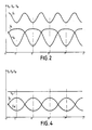
- the diffracted light is detected by photodetectors which transform the light signal into an electrical signal. If the light spot T is displaced in the direction symbolized by the arrow C in FIG. 1, at the lines AA and BB which cross the pre-etching marks 23 and 33 respectively in the center C, D and E, F of these pre-engraving marks, the curves V A and V B shown in FIG. 2 are respectively obtained.
- the abscissa Or represents the distance to the center of the disc.
- the object of the present invention is to provide a new pre-engraved information carrier with offset marks, the structure of the marks making it possible to obtain a curve V S parallel to the axis Gold.
- the subject of the present invention is an information medium comprising at least one face intended for recording, along tracks, optically readable information, the medium being provided with pre-engraving zones alternating with zones intended for recording of said information, the pre-etching zones comprising discrete patterns materializing the mean axis of the tracks, characterized in that, in each pre-etching zone, the discrete patterns are constituted by marks centered midway between two adjacent tracks and having an optical width, as provided by an actual optic with a limited transfer function, in the direction perpendicular to the axis of the tracks, substantially equal to the optical width of the zone located between two successive marks in said direction and in this that, from one pre-engraving zone to the next, the marks have equal offsets and opposite signs with respect to the central axes yen tracks.
- the present invention also relates to a method for producing marks offset relative to the mean axis of the tracks on an information medium as defined above.
- the marks deported on one side are engraved by deflection of the etching beam when passing over a first track and the marks deported on the other side by deflection of the engraving beam during the passage on a second track adjacent to the first track and then repeating the above operation until the end of the etching of the father support.
- the marks offset by deflection of the etching beam are engraved alternately on one side and the other of the mean axis of the tracks, a first part of the mark being engraved during the passage of the beam on a first track and a second part of the axially complementary mark being engraved during the passage of the beam on a second track adjacent to the first track.
- the present invention also relates to a method for producing an error signal for radial tracking of a track by a light spot for exploring the tracks of an information medium as described above, in which at least once carries out the sum of the signals detected by optical detection means during the passage of the light spot on two remote marks respectively on one side and the other and this sum is memorized, then one elaborates the radial track tracking error signal by alternately subtracting said sum from the signal detected during the passage of the light spot on one of the offset marks and the signal detected during the passage of the light spot on the other offset mark at said sum.
- the pre-etching zones 5 have a single mark offset, namely the marks 23 ′ for the pre-etching area 5 A , and the marks 33 ′ for the pre-etching area 5 B.
- the offset pre-etching marks 23 ′ and 33 ′ are chosen to have the same radial optical dimension r as the radial area r ′ situated between these same marks.
- the marks are centered exactly halfway between the tracks between which they are located, as symbolized by the references C′-D ′ and E′-F ′, which represent the center of said offset marks, respectively 23 ′ and 33 ′.
- the offset marks have equal offsets and opposite signs with respect to the mean axes of the tracks as represented by the mark 23 ′ centered in C ′ and mark 33 ′ centered in E ′ with respect to axis 1a or mark 23′centered in D ′ and mark 33 ′ centered in E ′ with respect to axis 1b.
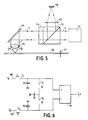
- This information carrier is used in a device for reading and recording optical discs as shown diagrammatically in FIG. 5.
- This device is composed of a laser module 51 providing a cylindrical light beam represented by the arrows f , of a cube polarization splitter 52 and a quarter-wave plate 53, a deflection mirror 54 serving for the tracking of track deviation, an objective 55 making it possible to focus the beam f on the disc and the disc 56 with axis 57.
- the beam f arriving on the disk is denoted II and the beam diffracted by the disk DD.
- the part of the beam DD which again enters the objective 55 meets the mirror 54 then the blade 53.
- This part f ′ of beam is then returned by the cube 52 to the lens 57 and to a photodetector device 58 which allows the measurement of part f ′ of the DD beam returning to objective 55.
- V S ′ results from the fact that the marks 23 ′ and 33 ′ are of the same radial optical dimension as the radial zone situated between two marks 23 ′ or two marks 33 ′ and that they are centered exactly midway between the tracks between which they are situated as represented by the references C ′, E ′, D ′, F ′ on the axis O′r ′ which correspond to the position of the centers of the offset marks represented in FIG. 3.
- this does not mean that the radial optical dimension of the marks 23 ′ or of the marks 33 ′ is equal to that of the radial zone situated between two marks 23 ′ or two marks 33 ′ when observed with an optic of infinite transfer function and therefore that these marks and these zones have the same geometric dimension.
- V S ′ V A ′ + V B ′ depends on the local properties of the disc and can vary. However, experience shows that this signal varies slowly and that even if it is necessary to know the signal V S ′ it must be determined at a lower frequency than the signal V A ′ or that the signal V B ′ , which allows to keep only one mark shifted by pre-etching areas 5.
- this device consists of sampler-blockers symbolized by the capacitors 91, 92, 93 and by switches I1, I2, I3, I4 controlling their inputs.
- the signals from the sample-and-hold units are used to supply a subtractor 94 having two high impedance inputs.
- the switches I1 and I3 are controlled by a signal d while the switches I2 and I4 are controlled by a signal g .
- the signal d is active and closes the switches I1 and I3 for a limited time less than the duration of passage of the offset mark 23 ′ when one is on the same radius of the disc as this mark 23 ′ and it is inactive the rest of the time .
- the signal g is active and closes the switches I2 and I4 for an unlimited time less than the duration of passage of the offset mark 33 ′ when one is on the same radius of the disc as this mark 33 ′.
- the upper channel 100 of the device is supplied by the signal V A ′ from the photodetector, while the lower channel 101 is supplied by the signal V B ′ also from the photodetector.
- capacities 91 and 92 are equal to c and much smaller than the capacity 93 itself equals C. A ratio of 10 between these capacities is a reasonable value.
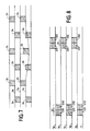
- the offset marks 24 or 34 located between tracks 1a and 1b or 1b and 1c are engraved in one go by deflection of the etching beam during its passage over one of the tracks.
- the marks 34 located between the tracks 1a and 1b are etched by deflection of the etching beam during its passage on the track 1b while the marks 24 located between the tracks 1b and 1c are etched all at once by deflection of the beam engraving during its passage on runway 1c.
- the marks 24 are therefore attached to the track 1c and the marks 34 to the track 1b. These two marks are used to control the light spot on track 1b.
- This embodiment of the offset marks can have drawbacks, in particular when a track has undergone locally, during its recording and for a fairly short duration, a deflection due to parasitic phenomena as has been represented in FIG. 7 for the track 1c.
- the deviation from track 1c which has been deliberately exaggerated in order to make it visible, introduces an error in the distance between tracks 1b and 1c and consequently the mark 24 associated with track 1c is moved relative to the track 1b.
- this mark 24 is associated with the mark 34, it creates an erroneous track error signal.
- the offset marks 23 and 33 are each made in two parts referenced 231 and 232 or 331 and 332.
- the offset marks are engraved using two successive passages of the beam of engraving.
- the mark 231 can be etched by deflecting the etching beam on the right then the mark 331 will be etched by deflecting the etching beam on the left.
- the reading beam is slaved to track 1b, we will burn part 232 by deflecting the reading beam on the left and part 332 of the mark 33 provided between tracks 1b and 1c by deflecting the reading beam on the right and so on for all brands.
- an error signal V A ′ is generated by summing the two signals V A′1 and V A′2 originating from the sampling respectively of the half-mark 231 and of the half-mark 232.
- the signal V B ′ is generated by summing the two signals V B′1 and V B′2 originating from the sampling of the half-mark respectively mark 331 and half mark 332. It is thus possible at any time to average the effect of variation of the center distance of the runway. This can have advantages insofar as the engraving of two half-marks one after the other can produce a more satisfactory result when the disc -father is burned than the superimposition over their entire length of two marks .
Landscapes
- Engineering & Computer Science (AREA)
- Manufacturing & Machinery (AREA)
- Optical Recording Or Reproduction (AREA)
Applications Claiming Priority (2)
| Application Number | Priority Date | Filing Date | Title |
|---|---|---|---|
| FR9004236A FR2660461B1 (fr) | 1990-04-03 | 1990-04-03 | Support d'informations pregrave a marques deportees, procede de realisation des marques ainsi que procede d'elaboration d'un signal d'erreur de suivi radial et dispositif de lecture pour la mise en óoeuvre du procede. |
| FR9004236 | 1990-04-03 |
Publications (2)
| Publication Number | Publication Date |
|---|---|
| EP0453343A1 true EP0453343A1 (de) | 1991-10-23 |
| EP0453343B1 EP0453343B1 (de) | 1997-07-16 |
Family
ID=9395389
Family Applications (1)
| Application Number | Title | Priority Date | Filing Date |
|---|---|---|---|
| EP19910400858 Expired - Lifetime EP0453343B1 (de) | 1990-04-03 | 1991-03-29 | Verfahren zur Herstellung von verschobenen pits auf einem vorgeprägten Informationsmedium, Verfahren zur Ausverarbeitung eines Spurfehlersignals und Wiedergabegerät zur Realisierung dieses Verfahrens |
Country Status (5)
| Country | Link |
|---|---|
| EP (1) | EP0453343B1 (de) |
| JP (1) | JPH04228115A (de) |
| CA (1) | CA2039527A1 (de) |
| DE (1) | DE69126817T2 (de) |
| FR (1) | FR2660461B1 (de) |
Cited By (3)
| Publication number | Priority date | Publication date | Assignee | Title |
|---|---|---|---|---|
| EP0562595A3 (en) * | 1992-03-26 | 1994-07-06 | Matsushita Electric Industrial Co Ltd | Apparatus for positioning optical head on a track of rotating disk |
| DE19623307B4 (de) * | 1995-06-30 | 2005-10-20 | Ferag Ag | Vorrichtung zum Handhaben von Druckereiprodukten |
| DE19623306B4 (de) * | 1995-06-30 | 2005-10-27 | Ferag Ag | Vorrichtung zum Verarbeiten von Druckereiprodukten |
Citations (6)
| Publication number | Priority date | Publication date | Assignee | Title |
|---|---|---|---|---|
| EP0089274A1 (de) * | 1982-03-12 | 1983-09-21 | Thomson-Csf | Optischer Informationsträger, optische Anordnung zur Spurfolge und optische Anordnung zur Erzeugung eines Fehlersignals zur Scharfeinstellung |
| GB2167595A (en) * | 1984-11-21 | 1986-05-29 | Drexler Tech | A laser recordable wallet-size plastics card and a method of making same |
| EP0201093A1 (de) * | 1985-05-10 | 1986-11-12 | Thomson S.A. | Vorgravierter Informationsträger und optische Lesevorrichtung dafür |
| EP0283017A1 (de) * | 1987-03-20 | 1988-09-21 | Hitachi, Ltd. | Informationsgewinnungssystem mit Kompensation des Spurfehlers |
| FR2613865A1 (fr) * | 1982-03-12 | 1988-10-14 | Thomson Csf | Support d'information mobile pregrave et dispositif optique de suivi de piste mettant en oeuvre un tel support |
| EP0320975A2 (de) * | 1987-12-18 | 1989-06-21 | Hitachi, Ltd. | Verfahren und Gerät zur Datenaufnahme/Wiedergabe |
-
1990
- 1990-04-03 FR FR9004236A patent/FR2660461B1/fr not_active Expired - Fee Related
-
1991
- 1991-03-29 DE DE1991626817 patent/DE69126817T2/de not_active Expired - Fee Related
- 1991-03-29 EP EP19910400858 patent/EP0453343B1/de not_active Expired - Lifetime
- 1991-04-02 CA CA 2039527 patent/CA2039527A1/en not_active Abandoned
- 1991-04-03 JP JP9812091A patent/JPH04228115A/ja active Pending
Patent Citations (6)
| Publication number | Priority date | Publication date | Assignee | Title |
|---|---|---|---|---|
| EP0089274A1 (de) * | 1982-03-12 | 1983-09-21 | Thomson-Csf | Optischer Informationsträger, optische Anordnung zur Spurfolge und optische Anordnung zur Erzeugung eines Fehlersignals zur Scharfeinstellung |
| FR2613865A1 (fr) * | 1982-03-12 | 1988-10-14 | Thomson Csf | Support d'information mobile pregrave et dispositif optique de suivi de piste mettant en oeuvre un tel support |
| GB2167595A (en) * | 1984-11-21 | 1986-05-29 | Drexler Tech | A laser recordable wallet-size plastics card and a method of making same |
| EP0201093A1 (de) * | 1985-05-10 | 1986-11-12 | Thomson S.A. | Vorgravierter Informationsträger und optische Lesevorrichtung dafür |
| EP0283017A1 (de) * | 1987-03-20 | 1988-09-21 | Hitachi, Ltd. | Informationsgewinnungssystem mit Kompensation des Spurfehlers |
| EP0320975A2 (de) * | 1987-12-18 | 1989-06-21 | Hitachi, Ltd. | Verfahren und Gerät zur Datenaufnahme/Wiedergabe |
Cited By (3)
| Publication number | Priority date | Publication date | Assignee | Title |
|---|---|---|---|---|
| EP0562595A3 (en) * | 1992-03-26 | 1994-07-06 | Matsushita Electric Industrial Co Ltd | Apparatus for positioning optical head on a track of rotating disk |
| DE19623307B4 (de) * | 1995-06-30 | 2005-10-20 | Ferag Ag | Vorrichtung zum Handhaben von Druckereiprodukten |
| DE19623306B4 (de) * | 1995-06-30 | 2005-10-27 | Ferag Ag | Vorrichtung zum Verarbeiten von Druckereiprodukten |
Also Published As
| Publication number | Publication date |
|---|---|
| JPH04228115A (ja) | 1992-08-18 |
| FR2660461B1 (fr) | 1994-10-28 |
| DE69126817D1 (de) | 1997-08-21 |
| FR2660461A1 (fr) | 1991-10-04 |
| DE69126817T2 (de) | 1997-11-20 |
| EP0453343B1 (de) | 1997-07-16 |
| CA2039527A1 (en) | 1991-10-04 |
Similar Documents
| Publication | Publication Date | Title |
|---|---|---|
| EP0089274B1 (de) | Optischer Informationsträger, optische Anordnung zur Spurfolge und optische Anordnung zur Erzeugung eines Fehlersignals zur Scharfeinstellung | |
| EP0089263B1 (de) | Vorgeprägter beweglicher Informationsträger und optische Spurfolgeanordnung dafür | |
| FR2569038A1 (fr) | Appareil d'enregistrement et de reproduction d'informations | |
| FR2490385A1 (fr) | Appareil d'asservissement de trace pour un systeme de reproduction d'informations optiques | |
| EP0097092A1 (de) | Verfahren und optisches Gerät zum Fokussieren eines Lichtstrahlbündels auf eine Bezugsebene eines Informationenträgers | |
| NL8800809A (nl) | Inrichting voor het opslaan van informatie op een van een lichtgevoelige bekledingslaag voorziene informatiedrager. | |
| FR2520542A1 (fr) | Systeme de commande d'alignement pour des disques sans sillon | |
| FR2527370A1 (fr) | Systeme de detection d'erreurs de focalisation opto-electronique | |
| FR2619241A1 (fr) | Procede et dispositif de controle de la mise au point, notamment pour le lecteur de disque optique numerique | |
| US4549288A (en) | Apparatus for enhancing the playback signal in an optical data recording system | |
| EP0090690A1 (de) | Verfahren und Anordnung zur Regenerierung der Phase der Synchronisationssignale in einem optischen Aufzeichnungswiedergabegerät für Informationsträger | |
| FR2558001A1 (fr) | Procede et appareil pour la recherche d'une piste sur un support optique d'information. | |
| EP0133067B1 (de) | Verfahren und Anordnung zur Regenerierung von wiedergegebenen, auf einer optischen Platte aufgezeichneten Datensignalen | |
| EP0077693B1 (de) | Opto-elektronische Vorrichtung zum Auslesen der Information eines magnetischen Aufzeichnungsträgers | |
| EP0022682B1 (de) | Optischer Lesekopf mit Halbleiter-Laserquelle und eine mit optischer Reflexion arbeitende Lesevorrichtung zum Lesen eines Informationsträgers, die einen solchen optischen Lesekopf enthält | |
| FR2511537A1 (fr) | Dispositif optique de suivi de piste a echantillonnage | |
| EP0453343B1 (de) | Verfahren zur Herstellung von verschobenen pits auf einem vorgeprägten Informationsmedium, Verfahren zur Ausverarbeitung eines Spurfehlersignals und Wiedergabegerät zur Realisierung dieses Verfahrens | |
| EP0056920A1 (de) | Optische Einrichtung zur Aufzeichnung und Wiedergabe von einem Informationsträger mit zwei Laserquellen verschiedener Wellenlängen | |
| EP0789907B1 (de) | Fokussierungssteuersystem | |
| EP0543707A1 (de) | Vorrichtung zum Spurzugriff und zur Spurverfolgung für optische Platte | |
| FR2613865A1 (fr) | Support d'information mobile pregrave et dispositif optique de suivi de piste mettant en oeuvre un tel support | |
| EP0064438A1 (de) | Aufzeichnungs-/Wiedergabeanordnung, die einen beweglichen Informationsträger mit einer vorgeprägten Spur enthält | |
| EP1502257B1 (de) | Radialsteuerverfahren für eine einrichtung zur wiedergabe von informationen eines optischen datenträgers und wiedergabeeinrichtung zur ausführung des verfahrens | |
| FR2676565A1 (fr) | Support d'informations lisibles optiquement et appareil de lecture d'un tel support. | |
| JP2007148148A (ja) | ホログラム再生方法および再生装置とエリアセンサ |
Legal Events
| Date | Code | Title | Description |
|---|---|---|---|
| PUAI | Public reference made under article 153(3) epc to a published international application that has entered the european phase |
Free format text: ORIGINAL CODE: 0009012 |
|
| AK | Designated contracting states |
Kind code of ref document: A1 Designated state(s): DE FR GB IT NL SE |
|
| 17P | Request for examination filed |
Effective date: 19920125 |
|
| 17Q | First examination report despatched |
Effective date: 19940826 |
|
| GRAG | Despatch of communication of intention to grant |
Free format text: ORIGINAL CODE: EPIDOS AGRA |
|
| GRAH | Despatch of communication of intention to grant a patent |
Free format text: ORIGINAL CODE: EPIDOS IGRA |
|
| GRAH | Despatch of communication of intention to grant a patent |
Free format text: ORIGINAL CODE: EPIDOS IGRA |
|
| GRAA | (expected) grant |
Free format text: ORIGINAL CODE: 0009210 |
|
| AK | Designated contracting states |
Kind code of ref document: B1 Designated state(s): DE FR GB IT NL SE |
|
| REF | Corresponds to: |
Ref document number: 69126817 Country of ref document: DE Date of ref document: 19970821 |
|
| GBT | Gb: translation of ep patent filed (gb section 77(6)(a)/1977) |
Effective date: 19970918 |
|
| PG25 | Lapsed in a contracting state [announced via postgrant information from national office to epo] |
Ref country code: SE Effective date: 19971016 |
|
| PLBE | No opposition filed within time limit |
Free format text: ORIGINAL CODE: 0009261 |
|
| STAA | Information on the status of an ep patent application or granted ep patent |
Free format text: STATUS: NO OPPOSITION FILED WITHIN TIME LIMIT |
|
| 26N | No opposition filed | ||
| PGFP | Annual fee paid to national office [announced via postgrant information from national office to epo] |
Ref country code: FR Payment date: 19990305 Year of fee payment: 9 |
|
| PGFP | Annual fee paid to national office [announced via postgrant information from national office to epo] |
Ref country code: DE Payment date: 19990324 Year of fee payment: 9 |
|
| PGFP | Annual fee paid to national office [announced via postgrant information from national office to epo] |
Ref country code: GB Payment date: 19990326 Year of fee payment: 9 |
|
| PGFP | Annual fee paid to national office [announced via postgrant information from national office to epo] |
Ref country code: NL Payment date: 19990331 Year of fee payment: 9 |
|
| PG25 | Lapsed in a contracting state [announced via postgrant information from national office to epo] |
Ref country code: GB Free format text: LAPSE BECAUSE OF NON-PAYMENT OF DUE FEES Effective date: 20000329 |
|
| PG25 | Lapsed in a contracting state [announced via postgrant information from national office to epo] |
Ref country code: NL Free format text: LAPSE BECAUSE OF NON-PAYMENT OF DUE FEES Effective date: 20001001 |
|
| GBPC | Gb: european patent ceased through non-payment of renewal fee |
Effective date: 20000329 |
|
| PG25 | Lapsed in a contracting state [announced via postgrant information from national office to epo] |
Ref country code: FR Free format text: LAPSE BECAUSE OF NON-PAYMENT OF DUE FEES Effective date: 20001130 |
|
| NLV4 | Nl: lapsed or anulled due to non-payment of the annual fee |
Effective date: 20001001 |
|
| REG | Reference to a national code |
Ref country code: FR Ref legal event code: ST |
|
| PG25 | Lapsed in a contracting state [announced via postgrant information from national office to epo] |
Ref country code: DE Free format text: LAPSE BECAUSE OF NON-PAYMENT OF DUE FEES Effective date: 20010103 |
|
| PG25 | Lapsed in a contracting state [announced via postgrant information from national office to epo] |
Ref country code: IT Free format text: LAPSE BECAUSE OF NON-PAYMENT OF DUE FEES Effective date: 20050329 |