EP0453404A2 - Machine à affranchir avec compteur mécanique - Google Patents
Machine à affranchir avec compteur mécanique Download PDFInfo
- Publication number
- EP0453404A2 EP0453404A2 EP91810266A EP91810266A EP0453404A2 EP 0453404 A2 EP0453404 A2 EP 0453404A2 EP 91810266 A EP91810266 A EP 91810266A EP 91810266 A EP91810266 A EP 91810266A EP 0453404 A2 EP0453404 A2 EP 0453404A2
- Authority
- EP
- European Patent Office
- Prior art keywords
- prepaid card
- locking
- blocking
- franking machine
- card slide
- Prior art date
- Legal status (The legal status is an assumption and is not a legal conclusion. Google has not performed a legal analysis and makes no representation as to the accuracy of the status listed.)
- Ceased
Links
Images




Classifications
-
- G—PHYSICS
- G07—CHECKING-DEVICES
- G07B—TICKET-ISSUING APPARATUS; FARE-REGISTERING APPARATUS; FRANKING APPARATUS
- G07B17/00—Franking apparatus
- G07B17/00016—Relations between apparatus, e.g. franking machine at customer or apparatus at post office, in a franking system
- G07B17/0008—Communication details outside or between apparatus
-
- G—PHYSICS
- G07—CHECKING-DEVICES
- G07B—TICKET-ISSUING APPARATUS; FARE-REGISTERING APPARATUS; FRANKING APPARATUS
- G07B17/00—Franking apparatus
- G07B17/00459—Details relating to mailpieces in a franking system
- G07B17/00508—Printing or attaching on mailpieces
-
- G—PHYSICS
- G07—CHECKING-DEVICES
- G07B—TICKET-ISSUING APPARATUS; FARE-REGISTERING APPARATUS; FRANKING APPARATUS
- G07B17/00—Franking apparatus
- G07B17/00016—Relations between apparatus, e.g. franking machine at customer or apparatus at post office, in a franking system
- G07B17/0008—Communication details outside or between apparatus
- G07B2017/00153—Communication details outside or between apparatus for sending information
- G07B2017/00177—Communication details outside or between apparatus for sending information from a portable device, e.g. a card or a PCMCIA
-
- G—PHYSICS
- G07—CHECKING-DEVICES
- G07B—TICKET-ISSUING APPARATUS; FARE-REGISTERING APPARATUS; FRANKING APPARATUS
- G07B17/00—Franking apparatus
- G07B17/00185—Details internally of apparatus in a franking system, e.g. franking machine at customer or apparatus at post office
- G07B17/00193—Constructional details of apparatus in a franking system
- G07B2017/00233—Housing, e.g. lock or hardened casing
-
- G—PHYSICS
- G07—CHECKING-DEVICES
- G07B—TICKET-ISSUING APPARATUS; FARE-REGISTERING APPARATUS; FRANKING APPARATUS
- G07B17/00—Franking apparatus
- G07B17/00185—Details internally of apparatus in a franking system, e.g. franking machine at customer or apparatus at post office
- G07B17/00193—Constructional details of apparatus in a franking system
- G07B2017/0025—Storage of, e.g. ribbon
-
- G—PHYSICS
- G07—CHECKING-DEVICES
- G07B—TICKET-ISSUING APPARATUS; FARE-REGISTERING APPARATUS; FRANKING APPARATUS
- G07B17/00—Franking apparatus
- G07B17/00459—Details relating to mailpieces in a franking system
- G07B17/00508—Printing or attaching on mailpieces
- G07B2017/00516—Details of printing apparatus
- G07B2017/00524—Printheads
- G07B2017/00548—Mechanical printhead
Definitions
- the invention relates to a franking machine with a mechanical counter for the units of value used for franking, an automatic blocking mechanism for blocking the franking machine at the end of a predetermined counter cycle and a printing device for printing the counter status at least at the end of this counter cycle, which are in drive connection with and opposite to counter wheels of the counter has type wheels arranged to a prepaid card slide, the prepaid card pusher being latched in the postage meter machine, the latching being releasable as a result of the pressure movement of the prepaid card pusher against the type wheels, and the blocking of the postage meter machine being releasable by inserting the prepaid card slide pusher into the postage meter machine.
- a franking machine of this type is known, for example, from DE-A-21 48 301.
- a prepaid card slide for a franking machine of this type is also described in GB-A-1,143,553. By means of a transverse movement, both the start and the end value of a counter cycle can be printed using this prepaid card slide.
- the known machines of this type have the disadvantage in common that the prepaid card slide can be inserted and locked again after the latch has been released when the machine is blocked, so that a new franking cycle can be started without billing with the post office, even if this is done by a corresponding later billing by a illegible double or multiple printing comes to the post office's knowledge and consequently to the proof of used units of value, the entire franking machine must be demonstrated to the post office.
- the object of the invention is to improve a franking machine of the type mentioned at the outset in such a way that its blocking is reliably prevented without the use of a new prepaid card.
- the prepaid card slide has a blocking device which interacts with blocking means arranged inside the franking machine and prevents the prepaid card slide from being pushed into its latching position and which can be automatically moved into a blocking position by triggering means arranged inside the franking machine, so that the latter blocking position after releasing the latching of the prepaid card slide, the blocking device being enclosed in a sealed seal on the prepaid card slide.
- the part of the franking machine 1 which has the mechanical counter 2 and the automatic blocking mechanism is enclosed in a sealed main housing 3, so that unauthorized manipulations on the counter are prevented.
- a sealed main housing 3 extends parallel to the counter 2, the hollow main machine shaft 4, which is rotated 360 ° either by hand using the crank 5 or an electric motor for franking.
- In the upper part of the main housing 3 are or the like for setting the desired or for the mailing of a specific letter. required franking value digit lever 6.
- This franking head is attached to the end of the machine main shaft 4 and enclosed in the upper part housing 7.
- a further partial housing 8 which includes a lever mechanism by means of which a pressure roller 9 is raised towards the franking head during franking, so that an envelope placed on the franking table 10 is pressed against the rotating franking head.
- the corresponding movement of the lever mechanism mentioned takes place by the partial rotation of a pressure shaft 11, which is actuated by a crank 12 (FIG. 6), which in turn is pivoted by a control lever 13 via an intermediate lever 14.
- the pivoting of the control lever 13 about the axis 16 mounted in a left intermediate wall 15 of the housing is brought about by a control roller 17 which rolls on the circumference of a control ring 18 fastened on the main shaft 4.
- the automatic blocking mechanism of the franking machine 1 has a blocking lever 20 which can be pivoted about an axis 19 and on which a blocking hook 21 is formed, which is provided for blocking the control lever 13 and thus the main shaft 4, for engagement with a bolt 22 fastened to the control lever. If the franking machine is not blocked, this blocking lever 20 is held up by a tension spring 23, so that the control lever can pivot freely when franking.
- the pivoting of the blocking lever 20 into the engagement position with the control lever 13, so that the blocking hook 21 hooks onto the bolt 22, is carried out by depressing a button 24 which projects laterally from the blocking lever 20, ie in the view according to FIG.
- the blocking lever 20 for non-automatic, ie arbitrary blocking of the franking machine from the outside can be pivoted downward into a blocking position by means of a key which can be plugged onto a shaft end 26.
- the shaft 27 having the shaft end 26 extends from the front housing wall 28 of the franking machine 1 into it, up to a second button 29 formed on the upper side of the blocking lever 20 and has an actuating cam 30 there for it.
- the switching disk 25 Before the franking machine 1 is blocked after consumption of a predetermined amount of value set on the counter 2, the switching disk 25 is in the upper position shown in FIG. 4 against the force of a tension spring 32 acting on its arm 31 and is there due to the engagement of a locking lever 33 locked in an incision 34. A spring 35 holds the locking lever 33 in this engaged position.
- the pivotable mounting of the locking lever 33 is provided by its attachment to a trigger shaft 36, which in turn is mounted in one of the two end walls 37, 38 of a holding frame 39 of the counter 2.
- the same end wall 37 also carries the pivot axis 40 of the switching disk 25, which extends parallel to it.
- a trigger lever On the trigger shaft 36, which runs parallel to a gear shaft carrying gears of the counter 2, a trigger lever is fastened, the hook-shaped free end of which rests on the hub of one of these gears under the pressure of the spring 35. At least one tooth provided on this hub pivots the trigger lever and thus the trigger shaft 36 with the locking lever 33 when the associated gear of the counter 2 has reached a rotational position which corresponds to the predetermined amount of value, the consumption of which the franking machine is to be blocked.
- By moving the trigger lever (not shown) on the trigger shaft 36 it can be placed against the gear wheel or its toothed hub, which results in the trigger movement of the trigger lever required for blocking when the quantity to be specified is reached.
- This locking pawl 51 serves to lock the camshaft 53 of the prepaid card carrier 54, which extends parallel to the counter 2, or to its gear shaft 55, 55, under the printing table 57. In the locking position, the locking pawl 51 engages in the correspondingly slotted end 58 of the camshaft 53 and is thus pivoted out of it in the release position.
- a release of the blocking of the franking machine in the manner described after reaching a predetermined counter reading of the counter 2 is only possible after actuation of the printing device, the inevitably following ejection of the value card slide 60 and insertion of a value card slide equipped with a new value card, since the pivoting back of the Switch disc 25 and thus the release of the blocking lever 20 is only possible by the insertion movement of the prepaid card slide 60 and a locking device 61 of the prepaid card slide 60 prevents the same prepaid card 62 from being inserted again.
- the corresponding mode of operation is described in more detail below.
- the printing device essentially consists of the type wheels 63 which are in drive connection with the gear wheels of the counter 2 and which correspond to the counter status adjust and the value card carrier 54 arranged below them, on which the value card slide 60 is held in guides 64, 65.
- This printing device is preferably designed such that it causes the printing of both the start and the end status of a counter cycle by transversely displacing the printing table 57 carrying the prepaid card slide 60.
- An exemplary embodiment of this can be found in GB-A-1,143,553.
- the transverse displacement takes place through the engagement of cams of the camshaft 53 on the printing table. Additional cams 67 raise and lower the printing table 57 in order to press the value card 62 against the type wheels 63.
- a cam is also provided on the camshaft 53, which actuates the locking pawl 68 for locking the value card slide 60 after the final status of a counter cycle has been printed on the value card 62.
- the hand crank 5 is plugged onto the externally accessible end 69 of the camshaft 53 and rotated to the right by approximately half a turn.
- the printing table 57 rises from the lower part of the prepaid card holder 54 against the force of tension springs 70, 71 upwards, so that the imprint on the prepaid card 62 takes place, and during the subsequent lowering, the locking pawl 68 is actuated, so that the prepaid card slide 60 is actuated by one the ejection slide 73 provided on the side of the value card carrier 54 and loaded by a tension spring 72 is ejected from the franking machine.
- a blocking device 61 which is described in more detail below, can only be reset by an authorized person of the post office, the prepaid card slide 60 is then brought to the post office for the billing of the used amount of value, in order to deliver another prepaid card slide 60 with a blocked blocking device 61 and a new prepaid card against payment receive.
- the locking device 61 of the prepaid card slider 60 is explained in more detail with reference to FIGS. 7 to 17. It has the task of blocking the insertion of the prepaid card slide 60 in a position in which its front edge 75 cannot yet lift the extension 76 (FIG. 3).
- Your locking member consists of a locking disk 87 which is pivotable about an axis 88 on a front extension, which forms the locking device 61 and forms part of the prepaid card slide 60, in such a way that a locking arm 89 integrally formed on it blocks the path into which one enters Posting device provided postage meter 90 moves when the prepaid card slide is fully inserted, ie until it causes the franking machine to be unblocked.
- the rigid base plate 91 of the prepaid card slide 60 which is formed, for example, in one piece from sheet metal.
- its longitudinal edges 92,93 are bent upwards.
- the value card 62 is inserted by bending and then stretching under a punched-out and bent tongue and under the transverse edge 95 of a flat housing cap 96 of the locking device 61.
- This housing cap 96 forms, together with the extension-like front area 97 of the rigid base plate 91, a closed housing in which the said locking disk, a locking pawl 98 and a pawl spring 99 are enclosed.
- the housing cap 96 is fastened to the front area 97 of the base plate 91 of the prepaid card slide 60 by sliding it lengthwise, so that two latches 100, 101 projecting forwardly offset from the base plate 91 and a third latch 103 at the rear end of the extension-like area 97 in openings 104 -106 come into engagement in the front and rear, downward edge 107, 108 of the housing cap 96.
- the locking disk 87 has the second function of securing the pushed-on housing cap 96 on the base plate 91.
- the locking disk 87 is pivoted into the position visible in FIG. 11 about the axis 88, in which its rear wing 109 swings partially behind a stop 110 formed on the inside of the housing cap 96, so that it is no longer possible to pull off the housing cap 96.
- a small circular opening 113, 114 is provided both in the locking disk 87 and in the housing cap 96, which is on a circular line with a center in the axis 88 are arranged and in the starting position of the locking disk 87 according to FIG. 12 are offset in the circumferential direction of this circular line, so that they are aligned with one another by pressing in a tapered pin 115 (FIG.
- the pointed pin 115 can be fastened in the bottom 116 of a packaging housing (FIG. 17) provided for the prepaid card slide 60, with which the franking machine owner can use a new or. gets newly loaded prepaid card slider 60 delivered by the post office. The swiveling movement of the locking disk 87 results accordingly when the prepaid card slide 60 is inserted into the packaging housing.
- a second pin 118 engages in the recess 119 of the housing cap 96, which is occupied by the locking arm 89 when the value card slide 60 is locked according to FIG. 13.
- the locked prepaid card slide 60 which has a used or printed prepaid card 62, can only be placed in the packaging housing in the reverse position.
- Holding cams 120, 121 provided on the bottom 116 of the packaging housing lie against the edge of the prepaid card slide in order to fix it.
- the further swiveling of the locking disk 87 from the position according to FIG. 11 before making a first impression on the prepaid card 62 into the position according to FIG. 13 after making the impression is carried out by a trigger element 124 which engages from the outside through an opening 123 likewise made impossible by the locking pawl 98 by engaging it under the pressure of the pawl spring 99 in a second cutout 125 of the locking disk 87.
- the pivoting back of the locking disk 87 against the securing against the use of the prepaid card slide 60 with the same prepaid card 62, which is to be prevented, is impossible since the parts enclosed by the housing cap 96 without destroying a membrane wall 126 of the housing cap 96 and pivoting back of the securing pawl 98 by the resultant Opening through, are not accessible.
- the edge of the housing cap 96 also extends accordingly along the incision 119 on the side 127 facing the securing pawl 98 and, with the exception of the openings 104-106, has only one interruption 128 in order to enable the movement of the locking arm 89 into the incision 119.
- the locking pawl 98 is made of a magnetically neutral material, for example plastic, and is mounted in its center of gravity about an axis 129, so that it cannot release the locking of the locking disk 87 by vibrations or magnetic forces.
- the small housing cap 96 manufactured as a plastic injection-molded part must be replaced by a new one due to the destroyed membrane wall 126, so that it has the function of a seal.
- their size is 20 x 35 mm.
- the base plate 91 has a forward-sloping extension 130 which, when the value card slide 60 is inserted into the franking machine 1, pushes back the locking pawl 68 (FIG. 2) provided on the value card carrier 54, so that it then engages behind this extension 130.
- a lateral extension 131 formed on the opposite side of the base plate 91 presses the ejection slide 73 against the tension spring 72 to the rear, or to the left in relation to the illustration in FIG. 1, so that the prepaid card slide 60 when the locking pawl 68 is pivoted back by the ejection slide 73 is ejected.
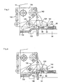
- the actuation of the release member 124 to lock the prepaid card slide 60 results from the lifting movement of the prepaid card carrier 54 serving for printing the prepaid card 62, with the prepaid card slide being held on it, as can be seen in the illustrations in FIGS. 7 to 9.
- an actuating arm 133 is attached to the side of the prepaid card carrier 54, which extends under the outer end 134 of a release lever 135, which is parallel to the left one Housing wall 15 extending and fastened to this support wall 136 is mounted about an axis 137, so that when the value card carrier 54 is lifted, the lever end 134 is pressed upward and the hook-shaped release member 124 provided on the other lever end swings downward accordingly.
- the lever end 134 is pressed upward and the hook-shaped release member 124 provided on the other lever end swings downward accordingly.
- FIG. 8 shows an intermediate position of this pivoting movement of the release lever 135.
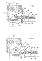
- FIG. 10 shows the second transverse position of the value card carrier 54, which occurs after the previously described lifting movement for producing the first impression on the value card or. the initial state of a counter cycle has ended. From this position, at the end of the counter cycle, the final imprint is made on the prepaid card, which leads to the ejection of the prepaid card slide 60.
- the locking arm 89 of the prepaid card slide 60 pivots into a path, ie into its recess 119, into which a stop element 90 provided in the franking machine 1 moves when the prepaid card slide 60 is fully inserted.
- This stop member 90 consists of the hook-shaped downward end of a stop lever 138, which is also mounted about the axis 137 and is located between the carrier wall 136 and the left housing wall 15.
- this stop lever 138 executes a pivoting movement opposite to the release lever 135, in that case a second actuating arm 139 with its cranked part 140 adjoins the actuating arm 133 in the longitudinal direction of the prepaid card slide, is cranked up and then runs behind the stop lever 138 from presses against the arm 141 facing the prepaid card holder, or its stop 142.
- the stop lever 138 frees up the space in the recess 119 of the prepaid card slide 60 when the release lever 135 pivots the locking arm 89 toward this space.
- Both levers 135, 138 are loaded by tension springs 143, 144 fastened to the carrier wall 136 against their pivoting movement triggered by the lifting movement of the prepaid card carrier 54.
- the part 145 of the actuating arm 139 which extends behind the stop lever 138 or its stop member 90 serves to support the stop member 90 from the rear if a greater force is expended against this stop member when the blocked prepaid card slide 60 is inserted. In this way, damage to the stop lever 138 is prevented.
- the production of the locking device 61 on the prepaid card slide 60 is simple, since the locking disk 87 and the locking pawl 98 can only be plugged onto axle bolts fastened to the base plate 91 and are secured against falling off the axle bolts 88, 129 by the attached housing cap 96.
- the spring 99 loading the locking pawl 98 can also be held, however, in reverse order of the arrangement, pins can also be formed on the parts to be fastened, which are inserted into holes in the base plate.
- the spring 99 consists of a spring rod formed from plastic with a web-shaped fastening part 146 running transversely thereto, on each end of which an anchoring pin 147, 148 is formed, which are pressed into holes in the base plate 91.
- an ink ribbon can be glued to its top along its longitudinal edges, which is provided with the ink layer on the inside.
Landscapes
- Physics & Mathematics (AREA)
- General Physics & Mathematics (AREA)
- Engineering & Computer Science (AREA)
- Computer Security & Cryptography (AREA)
- Devices For Checking Fares Or Tickets At Control Points (AREA)
Applications Claiming Priority (2)
| Application Number | Priority Date | Filing Date | Title |
|---|---|---|---|
| CH1346/90 | 1990-04-20 | ||
| CH134690A CH680095A5 (fr) | 1990-04-20 | 1990-04-20 |
Publications (2)
| Publication Number | Publication Date |
|---|---|
| EP0453404A2 true EP0453404A2 (fr) | 1991-10-23 |
| EP0453404A3 EP0453404A3 (en) | 1992-03-25 |
Family
ID=4208330
Family Applications (1)
| Application Number | Title | Priority Date | Filing Date |
|---|---|---|---|
| EP19910810266 Ceased EP0453404A3 (en) | 1990-04-20 | 1991-04-11 | Franking machine with mechanical meter |
Country Status (2)
| Country | Link |
|---|---|
| EP (1) | EP0453404A3 (fr) |
| CH (1) | CH680095A5 (fr) |
Family Cites Families (5)
| Publication number | Priority date | Publication date | Assignee | Title |
|---|---|---|---|---|
| CH514202A (de) * | 1970-10-19 | 1971-10-15 | Frama Ag | Verriegelungssystem an einer Frankiermaschine |
| US4629871A (en) * | 1979-12-28 | 1986-12-16 | Pitney Bowes, Inc. | Electronic postage meter system settable by means of a remotely generated input device |
| US4724310A (en) * | 1984-07-02 | 1988-02-09 | Tokyo Tatsuno Co., Ltd. | Device for inserting and holding an IC card as an external memory during reading and writing operations |
| US4901241A (en) * | 1988-03-23 | 1990-02-13 | Drexler Technology Corporation | Debit card postage meter |
| EP0363992B1 (fr) * | 1988-10-14 | 1996-04-03 | Omron Corporation | Lecteur de carte pourvu d'un mécanisme de verrouillage |
-
1990
- 1990-04-20 CH CH134690A patent/CH680095A5/de not_active IP Right Cessation
-
1991
- 1991-04-11 EP EP19910810266 patent/EP0453404A3/de not_active Ceased
Also Published As
| Publication number | Publication date |
|---|---|
| EP0453404A3 (en) | 1992-03-25 |
| CH680095A5 (fr) | 1992-06-15 |
Similar Documents
| Publication | Publication Date | Title |
|---|---|---|
| DE744946C (de) | Durch Zaehlkarten gesteuerte druckende Geschaeftsmaschine | |
| EP0105424B1 (fr) | Dispositif de sélection pour roues porte-caractère d'une imprimante | |
| DE2729274C3 (de) | Ein-Touren-Antrieb | |
| DE637951C (de) | Druckvorrichtung | |
| DE2506069B2 (de) | Fangvorrichtung zum Verhindern des Doppelausschlags eines Druckhammers | |
| DE3885519T2 (de) | Apparat für elektrisch angetriebenen Schalter. | |
| EP0453404A2 (fr) | Machine à affranchir avec compteur mécanique | |
| DE1956613B2 (de) | Zeitstempelmaschine | |
| DE69602400T2 (de) | Anzeigevorrichtung eines unerlaubten zugriffs | |
| DE3105229C1 (de) | Vorrichtung zum Transportieren und Heben von Farbbaendern in Schreib- oder aehnlichen Maschinen | |
| EP0235745B1 (fr) | Machine à affranchir | |
| DE3345160A1 (de) | Modulare sperreinrichtung fuer eine einziehvorrichtung fuer sicherheitsgurte | |
| EP0222275B1 (fr) | Machine à affranchir | |
| DE2623941C3 (de) | Verkaufsautomat mit voneinander getrennten Fächern | |
| DE2157871A1 (de) | Wertausgabemaschine, insbesondere Wertstempelmaschine | |
| DE2510584A1 (de) | Muenzausloesungsvorrichtung fuer mechanische warenautomaten | |
| DE580893C (de) | Wertstempelmaschine | |
| DE2445279A1 (de) | Druckvorrichtung mit mehreren einzeln elektromagnetisch einstellbaren zeichentraegern | |
| DE69306233T2 (de) | Vorrichtung zur Verriegelung der Typenräder einer Frankiermaschine | |
| DE2045613A1 (de) | Sperrvorrichtung fur Buromaschinen mit elektrischer Tastatur | |
| DE2148301A1 (de) | Verriegelungssystem an einer Frankiermaschine | |
| AT129561B (de) | Registriermaschine mit Wiederholungsvorrichtung für Einzelbetragsaufnahme, sowie Zwischen- und Endsummenabnahme, insbesondere zur Fahrkartenherstellung od. dgl. | |
| DE252805C (fr) | ||
| DE265257C (fr) | ||
| DD201709A5 (de) | Automatische stricknadelauswahlvorrichtung |
Legal Events
| Date | Code | Title | Description |
|---|---|---|---|
| PUAI | Public reference made under article 153(3) epc to a published international application that has entered the european phase |
Free format text: ORIGINAL CODE: 0009012 |
|
| AK | Designated contracting states |
Kind code of ref document: A2 Designated state(s): AT BE DE FR GB IT NL SE |
|
| PUAL | Search report despatched |
Free format text: ORIGINAL CODE: 0009013 |
|
| AK | Designated contracting states |
Kind code of ref document: A3 Designated state(s): AT BE DE FR GB IT NL SE |
|
| 17P | Request for examination filed |
Effective date: 19920903 |
|
| 17Q | First examination report despatched |
Effective date: 19950125 |
|
| 18R | Application refused |
Effective date: 19950717 |