EP0105424B1 - Dispositif de sélection pour roues porte-caractère d'une imprimante - Google Patents
Dispositif de sélection pour roues porte-caractère d'une imprimante Download PDFInfo
- Publication number
- EP0105424B1 EP0105424B1 EP83109467A EP83109467A EP0105424B1 EP 0105424 B1 EP0105424 B1 EP 0105424B1 EP 83109467 A EP83109467 A EP 83109467A EP 83109467 A EP83109467 A EP 83109467A EP 0105424 B1 EP0105424 B1 EP 0105424B1
- Authority
- EP
- European Patent Office
- Prior art keywords
- franking
- adjusting
- push rod
- adjusting push
- setting mechanism
- Prior art date
- Legal status (The legal status is an assumption and is not a legal conclusion. Google has not performed a legal analysis and makes no representation as to the accuracy of the status listed.)
- Expired - Lifetime
Links
- 238000007639 printing Methods 0.000 title claims description 13
- 238000010276 construction Methods 0.000 claims description 2
- 238000011084 recovery Methods 0.000 claims 1
- 238000007373 indentation Methods 0.000 description 5
- 230000001960 triggered effect Effects 0.000 description 5
- 238000004519 manufacturing process Methods 0.000 description 4
- 238000000034 method Methods 0.000 description 3
- 230000000903 blocking effect Effects 0.000 description 2
- 238000012217 deletion Methods 0.000 description 2
- 230000037430 deletion Effects 0.000 description 2
- 230000000994 depressogenic effect Effects 0.000 description 2
- 238000006073 displacement reaction Methods 0.000 description 2
- 230000005284 excitation Effects 0.000 description 2
- 238000005096 rolling process Methods 0.000 description 2
- 238000005452 bending Methods 0.000 description 1
- 230000005540 biological transmission Effects 0.000 description 1
- 230000000881 depressing effect Effects 0.000 description 1
- 230000000694 effects Effects 0.000 description 1
- 230000000977 initiatory effect Effects 0.000 description 1
- 239000002184 metal Substances 0.000 description 1
- 230000003287 optical effect Effects 0.000 description 1
- 238000003860 storage Methods 0.000 description 1
- 238000005303 weighing Methods 0.000 description 1
- 238000004804 winding Methods 0.000 description 1
Images




Classifications
-
- G—PHYSICS
- G07—CHECKING-DEVICES
- G07B—TICKET-ISSUING APPARATUS; FARE-REGISTERING APPARATUS; FRANKING APPARATUS
- G07B17/00—Franking apparatus
- G07B17/00459—Details relating to mailpieces in a franking system
- G07B17/00508—Printing or attaching on mailpieces
-
- B—PERFORMING OPERATIONS; TRANSPORTING
- B41—PRINTING; LINING MACHINES; TYPEWRITERS; STAMPS
- B41J—TYPEWRITERS; SELECTIVE PRINTING MECHANISMS, i.e. MECHANISMS PRINTING OTHERWISE THAN FROM A FORME; CORRECTION OF TYPOGRAPHICAL ERRORS
- B41J7/00—Type-selecting or type-actuating mechanisms
- B41J7/48—Type carrier arrested in selected position by electromagnetic means
-
- G—PHYSICS
- G07—CHECKING-DEVICES
- G07B—TICKET-ISSUING APPARATUS; FARE-REGISTERING APPARATUS; FRANKING APPARATUS
- G07B17/00—Franking apparatus
- G07B17/00185—Details internally of apparatus in a franking system, e.g. franking machine at customer or apparatus at post office
- G07B17/00314—Communication within apparatus, personal computer [PC] system, or server, e.g. between printhead and central unit in a franking machine
-
- G—PHYSICS
- G07—CHECKING-DEVICES
- G07B—TICKET-ISSUING APPARATUS; FARE-REGISTERING APPARATUS; FRANKING APPARATUS
- G07B17/00—Franking apparatus
- G07B17/00185—Details internally of apparatus in a franking system, e.g. franking machine at customer or apparatus at post office
- G07B17/00314—Communication within apparatus, personal computer [PC] system, or server, e.g. between printhead and central unit in a franking machine
- G07B2017/00354—Setting of date
-
- G—PHYSICS
- G07—CHECKING-DEVICES
- G07B—TICKET-ISSUING APPARATUS; FARE-REGISTERING APPARATUS; FRANKING APPARATUS
- G07B17/00—Franking apparatus
- G07B17/00459—Details relating to mailpieces in a franking system
- G07B17/00508—Printing or attaching on mailpieces
- G07B2017/00516—Details of printing apparatus
- G07B2017/00524—Printheads
- G07B2017/00548—Mechanical printhead
Definitions
- the invention relates to an adjusting device for type wheels with the features of the preamble of claim 1 and a franking machine with at least one adjusting device according to claim 1.
- the franking machines currently in use e.g. B. with the type designation "FRAMA Mod. 100 electronic" of the applicant have an adjustment device for each type wheel, which is composed of numerous and complex to manufacture and assemble individual parts.
- Each setting device has a toothed rack which extends in the longitudinal direction through the drive shaft of the franking head and which engages on the one hand with the gearwheel of the type wheel and on the other hand with a gearwheel gear of an adjusting disk rotating with the shaft.
- a manually operated adjusting lever is brought into engagement with the adjusting disc and swiveled by an angle corresponding to the numerical value.
- This pivoting movement causes a displacement of the rack and thus a rotation of the type wheel into the desired setting position via the gearwheel gear arranged in the adjusting disc.
- the setting position in the adjusting disc is secured by locking means.
- the adjusting disc is provided with mechanical means which mechanically actuate a mechanical counter each time the franking head and thus also the steep disc is rotated, which counts the value units used during franking. Details of the mechanics used are e.g. B. the spare parts catalog belonging to the above machine type.
- a setting device for type wheels of a printing device with the features of the preamble of claim 1 is known from US-A-3 822 640. From this document it is known to rotate the respective type wheel for a printing device with stationary, rotatably mounted type wheels by means of two ratchet levers mounted on a swivel plate into the desired printing position. These ratchet levers are held in constant engagement with the driving ratchet wheel by spring force. Their pushing adjusting movement results from the back and forth swiveling movement of this swivel plate, which is coupled to two electromagnets arranged opposite to each other.
- the invention has for its object to find an adjusting device for type wheels of a printing device, the type wheels can perform a circular movement during printing, so that they can be provided on the circumference of a rotating printing roller or the franking head of a franking machine.
- the setting device should be compared with z. B. by LU-A-83 626 or US-A-4 050 374 known adjusting devices are easier to manufacture and assemble by mechanically simpler structure. This object is achieved according to the invention on the basis of the features of patent claim 1.
- a preferred combination of the setting device according to the invention with a franking machine is the subject of patent claim 5.
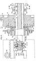
- a housing part of the franking machine is indicated by dashed lines 2, which is located on the side of a main housing, not shown, and includes the franking head 4.
- the general structure of a franking machine is assumed to be known. An example shows the commonly used machine of the applicant with the designation "FRAMA Mod. 100 electronic".
- the franking head is located above a franking table 6, over which envelopes are moved in the direction of the arrow 7 for printing with the franking value and the date.
- the franking head 4 rotates in accordance with the working cycle of the franking machine, triggered by a contact 9 arranged in the franking table and actuated by feeding an envelope, so that the cliché 8 for the franking value and the cliché 10 for the date roll on the envelope, not shown .
- the pressure is generated by the automatic stroke movement of the pressure roller 12 indicated by a dashed line.
- the stroke movement results from a lever movement of a drive transmission, not shown, which is caused by the rolling of a control roller 13 indicated by dashed lines in FIG. 5 on a control curve 15 of the control wheel 17 ( Fig. 12) is triggered.
- Dye is transferred to plates 8 and 10 by a rolling movement through an ink storage roller, not shown.
- a corresponding device is the subject of EP-A 0 064 125.
- a first example of use of the setting device according to the invention on a franking machine, shown in FIGS. 1 to 4, relates to the adjustment of the type wheels of the date plate 10 by the setting devices 14, 14 'acting from the circumference of the franking head.
- the setting device for the type wheels 18 to 21 of the date plate 10, which are shown enlarged in FIG. 4, has an input device 24 which has a plurality of switching buttons 25 which are used at the same time for setting the numbers of an electronic date display 26.
- An actuation of a switch button 25 triggers an electrical pulse, which is supplied via lines 28, 29 to both the date display 26 and the electromechanical actuation device 14 for the type wheels 18 to 21, as is shown schematically in FIG. 1 by a circuit.
- the adjusting device 14, 14 ' has an adjusting plunger 30, 32, or 30', 32 'for each type wheel to be adjusted. As shown in FIGS. 2 and 3, an adjusting device 14, 14 'can be provided on both sides of the date plate 10 or the franking head 4. Since these setting devices 14, 14 'can be designed identically, only the actuating device 14 is described below.
- the adjusting device has a z. B. vertically directed mounting plate 34, the z. B. is rigidly attached by means of screws 35 to an inner wall 39 of the franking machine located next to the franking head.
- This mounting plate 34 carries at least two and, in the present example, three electromagnets 36 to 38.
- the electromagnets 36, 37 serve to actuate the adjusting plungers 32, 30 and are fastened in parallel to one another directly on the mounting plate.
- the third electromagnet 38 is fastened to a bend 40 bent out perpendicularly from the mounting plate and thus directed perpendicular to the other electromagnets 36, 37.
- This third electromagnet 38 serves to pivot a guide plate 42, on which the adjusting slides 30, 32 slide, into a position in which the adjusting plungers 30, 32 engage with a gear 44, 45 for adjusting a type wheel 20 or 18 can reach.
- This guide plate 42 has a rectangular shape in side view (FIG. 2), with its shorter leg 43 running parallel to the mounting plate 34 and carrying a tension spring 47 at its free end, the other end of which is attached to the bend 40 of the mounting plate 34.
- the tension spring 47 thus holds the guide plate 42 in the waiting position shown in FIG. 2, in which the adjusting plungers 30, 32 are held at a distance from the franking head 4, so that the franking head 4 can rotate freely for franking.
- the third electromagnet 38 is provided, which pulls the longer leg 46 or its fork leg 49 (FIG. 3) downward against the tensile force of the return spring 47, so that with the guide plate 42, the adjusting plungers 30, 32 move into a pivoting position in which they can turn the adjusting wheel 44, 45 of a type wheel after longitudinal displacement by means of the electromagnets 36, 37.
- the electromagnets 36, 37 have an armature shaft 54, 55 which extends through the magnet winding and at one end of which the angled leg 58 of the associated adjusting plunger 30 and 32 is articulated.
- the armature shaft 54, 55 moves against the force of a tension spring 56, 57 fastened at one end thereof and thus pushes the adjusting plunger 30 or 32 forward in the direction of the rotary movement of the gear wheel 44 or 45.
- the articulated connection 60 between the anchor shaft 54 or 55 and the angled leg 58 of the adjustment plunger enables the pivoting movement of the adjustment plunger 30, 32 together with the guide plate 42.
- the adjustment plungers 30, 32 For the lateral guidance of the adjustment plungers 30, 32 on the guide plate 42, the latter is provided with an obliquely upwardly bent front end 62 and in its central region with a vertically upwardly bent plate part 64, in each of which there is a slot 65 to 68, which includes the adjusting plunger 30 or 32 stamped from a sheet metal part.
- the part 64 bent upwards at right angles from the guide plate 42 also serves as a stop for the longitudinal stroke movement of the adjusting plungers, in that they have a stop bolt 70, 71.
- a sliding cam 72 is formed on the underside of the adjusting plungers 30, 32, with which the adjusting plungers 30, 32 slide on the upper side of the guide plate 42.
- a small cover plate 74 is fastened at this point by means of a bolt 75 at a distance from the guide plate.
- the electromagnets 38 and 36 must be excited.
- the excitation current is triggered by depressing one of the switching buttons 25 (FIG. 1).
- the unit consisting of the guide plate 42 and the adjustment plunger 30, 32 first pivots downward and thus also the tip 78 of the adjustment plunger 30, 32 intended for engagement in the gearwheel 44 until the latter reaches a plane which corresponds to the pitch circle of the gearwheel 44 or 45 affects.
- the adjustment plunger 32 moves forward, so that the adjustment tip 78 engages in a tooth of the gearwheel and the gearwheel 44 rotates further by a certain angle with the type wheel 20 firmly connected to it.
- the type wheels 18 to 21 are coupled to an adjustment gear, to which an adjustment plunger is assigned, while the type wheel 80 has no adjustment gear for the setting of the 10s, since the adjustment to be carried out every 10 years
- Gear wheel is expediently carried out by hand using a pointed tool after a closing flap is opened in the housing of the franking machine and is located in the region of the franking head.
- an automatic triggering can also be carried out by means of a battery-operated clock with a date display.
- the adjusting device is preferably fastened in an adjustable manner in the circumferential direction relative to the franking head.
- the position of the adjusting plungers 30, 32 can be exactly aligned again with the adjusting gearwheels 44, 45 after the plate 10 has been exchanged for a different type of plate.
- the use of various clichés, e.g. B. on a franking machine, is otherwise the same construction of the franking machine is required to make an adjustment to changing needs, z. B. if the franking machine has to be adjusted at a different location or in a different country with different wishes or regulations when franking. It is possible for the group of date type wheels on the franking head to assume a different position in the circumferential direction.
- the adjustment of the adjusting device 14, 14 ' can be achieved in a simple manner by the screws 35, which attach the mounting plate 34 to the inner wall 39 of the franking machine, extending through an elongated opening 81 which either extends into the inner wall of the franking machine or are in the mounting plate, so that the screw can assume 81 different clamping positions in this opening.
- an actuating mechanism for the adjustment of the setting device 14, 14 'relative to the franking head in the circumferential direction, an actuating mechanism, not shown, which is actuated by hand or by a drive and can be provided with an electronic control, can also be used.
- Such an actuating mechanism makes it possible to adjust the actuating device in the circumferential direction relative to the franking head in such a wide range that the same adjusting device can be used by a plurality of clichés 8, 10 for the actuation of the type wheels or their gear wheels by appropriate movement in the circumferential direction . 1, such an adjusting mechanism can move the adjusting device 14 from the position shown in FIG. 1 over the plate 10 to a position in which it is above the plate 8.
- the guidance of this circumferential movement of the adjusting device can in a slot concentric with the circumference of the franking head, by guide rails, and the like. The like.
- the second cliché is the type wheels corresponding to the franking value has, so special measures are to be taken so that it is prevented that these type wheels, z. B. can be set from outside using an instrument in an unauthorized manner.
- mechanical rotation of the franking head when the franking machine was not switched on electrically would enable a value to be withdrawn or franked without the franking value being counted in the electronic memory provided for such a machine for the value units used.
- each adjusting device has a device part which is identical to one of the adjusting devices 14, 14 'described in the foregoing, corresponding to the illustrations in FIGS. 1 to 3, however, in contrast to an adjusting device 14, each adjusting device additionally has a rack-and-pinion slide valve 83 to 86 , which is arranged mechanically between the adjusting gear 88 of a type wheel and an adjusting plunger 89 or 90.
- the adjustment plungers 89, 90 correspond to the adjustment plungers 30, 32 and 30 ', 32' of the previously described setting devices 14, 14 'and are therefore only partially shown in FIG. 5.
- the adjusting slides 83 to 86 are guided in the shaft 16 of the franking machine. For this purpose, this has outwardly open guide slots 92 to 95, as can best be seen in FIG. 9.
- the numerical value is not entered in the display 26 directly by the electrical pulse triggered when the switch button 25 is depressed, but rather by the pulse of a photocell 98 which can be swiveled in the swivel range of about an axis 100
- Latches 101, 102 is arranged. There is a latch 101, 102, or 101 ', 102' for each of the adjusting slides 83 to 86, as the illustration in FIG. 5 shows. These overlap in the view according to FIG. 9, so that only a pair 101, 102 can be seen there.
- FIG. 9 shows the latches 101, 102, in the locked position, in that the area 103 is locked in the tooth space of the adjusting slide 84 and the area 104 of the locking lever 102 is locked in the tooth gap 105 of the adjusting slide 85.
- the adjustment plunger 89 pushes the associated adjustment slide further by one tooth, the pawl region 103 or 104 sliding over the sawtooth-shaped tooth 97, so that the latching lever 101, 102 executes a pivoting movement which leads to a temporary blocking the photocell 98 leads.
- This causes electronic feedback to the display register, which corresponds to register 26 in FIG. 1, which adds one digit to the previous numerical value.
- the photocell pair 98, 99 can thus electronically determine each position of the two latches 101, 101 'and 102, 102' arranged one above the other according to FIG. 9, so that the mechanical movement carried out is electronically confirmed.
- the secure latching of the latching levers is ensured by a tension spring 111, which connects the legs of the latching pawls 101, 102 to one another.
- the axes 100 of the latches 101, 102, 101 ', 102' are attached to the steering wheel 17, so that the latches rotate together with the steering wheel and the machine shaft 16 when franking.
- the side view of the steering wheel 17 shown on a smaller scale in FIG. 10 shows fastening holes 112 for fastening these axles 100.
- the area of the latches 101, 102 facing the machine shaft 16 is adapted outside the area of the adjusting slide to the shape of the shaft and engages in a circumferential groove 113 of the shaft, as shown in FIG. 9, so that the latches in this groove 113 are supported against lateral deflection in the direction of the shaft.
- the shaft 16 of the franking machine always takes exactly the same rotational position for the setting of the type wheels must, so that the arranged above and below the shaft and not rotating adjusting plunger 89, 90 can always be brought exactly into engagement with the teeth 97 of the associated adjusting slide 83 to 86.
- the shaft 16 and thus the franking head 4 are driven by the engagement of a drive pinion (not shown) in the ring gear 115 on the circumference of the control wheel 17.
- This pinion is driven by an electric motor (not shown) until the control wheel has made a 360 ° revolution.
- the shading of the electric motor driving the pinion is carried out in the usual way by a contact switch of a second control wheel, not shown, on the right end of the shaft 16.
- the pressure lever 120 of the control roller 17 is secured in the locking position shown in FIG. 10 by a pawl 122 by pulling it into the locking position by a spring 123. However, if there is a connection between the franking machine and the voltage source, an electromagnet 124 pulls the pawl into a release position.
- the control wheel 17 is driven again, so that the control roller 117 moves past the highest point 125 of the control curve 116 following the indentation 118 and the pressure lever 120 counteracts the force of the tension spring 119 about the axis 126 swings back.
- an anti-rebound pawl 128, indicated by broken lines in FIG. 12, is present, which extends over a ratchet tooth 129 moved and clicks behind it into the position shown.
- the direction of rotation of the steering wheel is indicated by an arrow 130 in FIGS. 10 and 12.
- the franking machine also has a device for mechanically locking the franking value, which has been set by moving the adjusting slides 83 to 86.
- This locking device comes into effect as soon as the shaft 16 has rotated through a small angle and is only released again when the set franking value is to be deleted again.
- two pawls 135, 136 are provided, which are provided for engaging the tooth spaces 137 of a rectangular toothing 138 of the adjusting slides 83 to 86 and are in engagement with a tooth space 137 in the representations corresponding to FIGS. 5 and 13.
- This rectangular toothing 138 is arranged in the longitudinal direction of the adjusting slide behind the row of adjusting teeth 97 and the tooth-free area 109, as also shown in FIGS. 6 and 7.
- Each pawl 135, 136 is used to block a similarly shaped adjusting slide 83, 85 or 84, 86, in that the pawl 135 for engaging in the rectangular toothing 138 of the adjusting slide 83, 85 and the pawl 136 for engaging in the rectangular toothing of the blocking slide 84, 86 is provided.
- 6 and 7 the toothings of which extend in opposite directions from the shaft axis in the sliding assembly 140, 141 extending through the shaft 16, since they are used for the adjustment by adjusting plungers arranged on opposite sides of the shaft 16 89, 90 are provided, as is also true for the latches 101, 102 according to FIG. 9.
- the pawls 135, 136 do not rotate with the control disk 17, but are pivotably mounted about a common fixed axis 142 in a wall of the machine housing.
- Each pawl 135, 136 has a control pin 143, 144, which are guided in a control groove 137, which is shown in FIG. 5 on the left side of the steering wheel 17 and is shown with its course in FIG. 12.
- the control disk rotates, the control pins 143, 144 and thus the pawls 135, 136, based on the machine shaft 16, are pulled radially inward into the respective tooth gap 137 corresponding to the setting position of the adjusting slide, and into an annular groove 150 of the shaft 16.
- the engagement edge 151, 152 of the pawls is designed in the shape of a circular arc. This engagement of the pawls in the groove 150 supports them against bending in the direction of the shaft 16. In the engaged position, the pawls 135, 136 are locked by a locking lever 154.
- This locking lever 154 is pivoted about a fixed axis 156 into engagement position with the pawls by a tension spring 155, in which two extensions 157, 158 of the pawls are held in a recess 160 of the locking lever 154.
- pawls 135, 136 remain in the locking position shown in FIGS. 5 and 13, so that the franking value set remains secured for several frankings with the same value. Only after initiation of the deletion process for the set franking value does the locking lever 154 release the pawls 135, 136 again by an electromagnet 161 pivoting the locking lever 144 back against the force of the spring 155. In the setting position of the shaft 16, the pawls 135, 136 can then move apart again by the tension of the springs 148, 149 in order to enable a new setting of the type wheels or franking values.
- the latches 101, 102, 101 ', 102' are also to be moved out of engagement with the teeth 97 of the advance slides 83 to 86, for which purpose a release lever 163 is provided, which is actuated by means of an electromagnet 164 against each lever arm 165 , 166 of the pawls 101, 102 presses, so that the pawls pivot against the force of the tension spring 111 about their axis 100 outwards.
- the tension springs 106 provided on each of these slides pull the adjustment slides back into their starting position, i.e. 5 to the right until they reach the position shown there.
- the edge 168 on the head part 169 of the adjusting slide comes into abutment with the end face 170 of the machine shaft 16.
- the latches 101, 102 are optically read by means of the photocells 98, 99 in order to determine whether all the racks are in the starting or zero position. If this is not the case, the deletion process is initiated, i.e. solenoids 161 and 164 are actuated to release pawls 135, 136 and pawls 101, 102.
- FIG. 5 shows one of two bearings 172 which is connected to an inner housing wall 173 of the franking machine by means of screws 174.
- the pawls 135, 136 and the Versteibtösset 89, 90 all parts shown in FIG. 5 perform the rotary movement together with the shaft 16 when franking.
- the photocells 98, 99 shown in FIG. 9 are also arranged in a fixed manner, since the optical reading of the position of the latches 101, 102 takes place only in the setting position of the shaft 16.
- setting devices 14, 14 'of the same design are used in a plurality on one franking machine, so that the production in series production is considerably simplified.
- an adjusting device 14, 14 ' each with two adjusting rams 30, 32; are for setting the date or for setting the cliché 10 on both sides of the franking head.
Landscapes
- Physics & Mathematics (AREA)
- General Physics & Mathematics (AREA)
- Engineering & Computer Science (AREA)
- Computer Security & Cryptography (AREA)
- General Engineering & Computer Science (AREA)
- Computer Hardware Design (AREA)
- Electromagnetism (AREA)
- Devices For Checking Fares Or Tickets At Control Points (AREA)
- Regulating Braking Force (AREA)
- Steering Control In Accordance With Driving Conditions (AREA)
- Impact Printers (AREA)
- Power Steering Mechanism (AREA)
- Labeling Devices (AREA)
Claims (11)
Priority Applications (1)
| Application Number | Priority Date | Filing Date | Title |
|---|---|---|---|
| AT83109467T ATE51312T1 (de) | 1982-10-04 | 1983-09-23 | Einstellvorrichtung fuer typenraeder einer druckeinrichtung. |
Applications Claiming Priority (2)
| Application Number | Priority Date | Filing Date | Title |
|---|---|---|---|
| CH5827/82 | 1982-10-04 | ||
| CH5827/82A CH663848A5 (de) | 1982-10-04 | 1982-10-04 | Einstelleinrichtung fuer typenraeder. |
Publications (3)
| Publication Number | Publication Date |
|---|---|
| EP0105424A2 EP0105424A2 (fr) | 1984-04-18 |
| EP0105424A3 EP0105424A3 (en) | 1987-02-04 |
| EP0105424B1 true EP0105424B1 (fr) | 1990-03-21 |
Family
ID=4299959
Family Applications (1)
| Application Number | Title | Priority Date | Filing Date |
|---|---|---|---|
| EP83109467A Expired - Lifetime EP0105424B1 (fr) | 1982-10-04 | 1983-09-23 | Dispositif de sélection pour roues porte-caractère d'une imprimante |
Country Status (6)
| Country | Link |
|---|---|
| US (1) | US4520725A (fr) |
| EP (1) | EP0105424B1 (fr) |
| JP (1) | JPH0643136B2 (fr) |
| AT (1) | ATE51312T1 (fr) |
| CH (1) | CH663848A5 (fr) |
| DE (1) | DE3381362D1 (fr) |
Families Citing this family (24)
| Publication number | Priority date | Publication date | Assignee | Title |
|---|---|---|---|---|
| US4603627A (en) * | 1984-03-23 | 1986-08-05 | Pitney Bowes Inc. | Rotary shutter device for a postal mailing system |
| US4774881A (en) * | 1985-09-23 | 1988-10-04 | Pitney Bowes Inc. | Rotary operated character selection system for postage meters |
| CH669056A5 (de) * | 1985-11-12 | 1989-02-15 | Frama Ag | Frankiermaschine. |
| CH670524A5 (fr) * | 1985-12-20 | 1989-06-15 | Hasler Ag Ascom | |
| CH669684A5 (fr) * | 1986-03-05 | 1989-03-31 | Frama Ag | |
| US4852482A (en) * | 1987-12-21 | 1989-08-01 | Pitney Bowes Inc. | Automatic printwheel setting system |
| US4875788A (en) * | 1987-12-21 | 1989-10-24 | Pitney Bowes Inc. | Postage meter printwheel setting apparatus |
| CH678366A5 (fr) * | 1989-03-08 | 1991-08-30 | Frama Ag | |
| CH678367A5 (fr) * | 1989-03-08 | 1991-08-30 | Frama Ag | |
| CH678368A5 (fr) * | 1989-03-29 | 1991-08-30 | Frama Ag | |
| US5050495A (en) * | 1989-05-05 | 1991-09-24 | Wu Sheng J | Print wheel setting mechanism |
| US5363760A (en) * | 1989-06-22 | 1994-11-15 | Ascom Hasler Ag | Rotor unit for a postage meter machine |
| CH679088A5 (fr) * | 1989-07-21 | 1991-12-13 | Frama Ag | |
| EP0422434B1 (fr) * | 1989-10-13 | 1994-12-07 | Ascom Hasler Mailing Systems AG | Dispositif de mise à la date du timbre à date d'une machine à affranchir |
| FR2665781B1 (fr) * | 1990-08-07 | 1993-06-11 | Alcatel Satmam | Dispositif de verrouillage de molettes d'une machine a affranchir. |
| FR2665782B1 (fr) * | 1990-08-07 | 1993-06-11 | Alcatel Satmam | Dispositif de reglage de molettes d'impression dans un machine a affranchir. |
| US5197042A (en) * | 1991-10-31 | 1993-03-23 | Pitney Bowes Inc. | Postage meter having auto dating device |
| US5495103A (en) * | 1994-03-16 | 1996-02-27 | Ascom Hasler Mailing Systems Ag | Optical mail piece sensor for postage meter |
| DE59510980D1 (de) * | 1995-03-07 | 2005-01-27 | Frama Ag | Vorrichtung für die Bestimmung eines Frankierwertes |
| EP1065630A1 (fr) * | 1995-04-14 | 2001-01-03 | Ascom Hasler Mailing Systems AG | Système de positionnement de roues de date d'une machine à affranchir |
| US5749291A (en) * | 1995-04-14 | 1998-05-12 | Ascom Hasler Mailing Systems Ag | System for setting date wheels in a postage meter |
| US7216742B2 (en) * | 2003-01-15 | 2007-05-15 | Spengler Robert G | Ladder stabilizers |
| US20080185225A1 (en) * | 2003-01-15 | 2008-08-07 | Spengler Robert G | Step ladder stabilizers |
| CN109411161B (zh) * | 2018-12-25 | 2024-01-26 | 上海起帆电缆股份有限公司 | 一种电缆外护套双侧印字设备 |
Family Cites Families (18)
| Publication number | Priority date | Publication date | Assignee | Title |
|---|---|---|---|---|
| US2510350A (en) * | 1947-10-18 | 1950-06-06 | Pitney Bowes Inc | Postage printing and metering device |
| CH284624A (de) * | 1950-05-17 | 1952-07-31 | Pitney Bowes Inc | Wertdruckvorrichtung an Frankiermaschinen. |
| DE1054257B (de) * | 1955-05-21 | 1959-04-02 | Kienzle Apparate Gmbh | Verfahren zur UEbertragung von in elektronischen Zaehlwerken vorhandenen Zaehlwerten in mechanische Druck- und/oder Zaehlwerke |
| DE1176406B (de) * | 1961-08-31 | 1964-08-20 | Licentia Gmbh | Impulszaehler |
| JPS5140771B2 (fr) * | 1971-08-17 | 1976-11-05 | ||
| DE2320792A1 (de) * | 1973-04-25 | 1974-11-14 | Carl Valentin Gmbh | Druckeinrichtung fuer den abdruck eingestellter zeichenwerte auf einen beweglichen aufzeichnungstraeger |
| US3916785A (en) * | 1974-06-03 | 1975-11-04 | Ncr Co | Imprinting means for a computer access terminal |
| FR2354602A1 (fr) * | 1976-06-09 | 1978-01-06 | Secap | Dispositif automatique de mise a valeur des molettes d'impression dans une machine a affranchir |
| US4050374A (en) * | 1976-06-21 | 1977-09-27 | Pitney-Bowes, Inc. | Meter setting mechanism |
| JPS5313465U (fr) * | 1976-07-12 | 1978-02-03 | ||
| JPS5540090Y2 (fr) * | 1976-08-25 | 1980-09-19 | ||
| JPS5350505U (fr) * | 1976-10-04 | 1978-04-28 | ||
| FR2377066A1 (fr) * | 1977-01-07 | 1978-08-04 | Secap | Perfectionnement aux dispositifs de securite dans une machine a affranchir electronique |
| JPS5397518A (en) * | 1977-02-02 | 1978-08-25 | Suwa Seikosha Kk | Small printer |
| JPS5913985B2 (ja) * | 1977-05-11 | 1984-04-02 | ミネベア株式会社 | プリンタの字輪リセツト機構 |
| JPS5919031B2 (ja) * | 1978-05-09 | 1984-05-02 | 株式会社オ−トスタンプ研究所 | 自動印字器 |
| DE2932425C2 (de) * | 1979-08-07 | 1986-01-02 | Francotyp - Postalia GmbH, 1000 Berlin | Vorrichtung zum Sperren und Ausrichten von druckenden Ziffernrollen und der Schalttrommel |
| DE3111949C2 (de) * | 1981-03-23 | 1985-06-20 | Francotyp - Postalia GmbH, 1000 Berlin | Einstellvorrichtung für Frankier- und Wertstempelmaschinen |
-
1982
- 1982-10-04 CH CH5827/82A patent/CH663848A5/de not_active IP Right Cessation
-
1983
- 1983-09-19 JP JP58172844A patent/JPH0643136B2/ja not_active Expired - Lifetime
- 1983-09-23 AT AT83109467T patent/ATE51312T1/de not_active IP Right Cessation
- 1983-09-23 DE DE8383109467T patent/DE3381362D1/de not_active Expired - Lifetime
- 1983-09-23 EP EP83109467A patent/EP0105424B1/fr not_active Expired - Lifetime
- 1983-09-28 US US06/536,763 patent/US4520725A/en not_active Expired - Lifetime
Also Published As
| Publication number | Publication date |
|---|---|
| EP0105424A3 (en) | 1987-02-04 |
| ATE51312T1 (de) | 1990-04-15 |
| CH663848A5 (de) | 1988-01-15 |
| EP0105424A2 (fr) | 1984-04-18 |
| DE3381362D1 (de) | 1990-04-26 |
| JPS59196274A (ja) | 1984-11-07 |
| JPH0643136B2 (ja) | 1994-06-08 |
| US4520725A (en) | 1985-06-04 |
Similar Documents
| Publication | Publication Date | Title |
|---|---|---|
| EP0105424B1 (fr) | Dispositif de sélection pour roues porte-caractère d'une imprimante | |
| DE2750673C2 (de) | Vorrichtung zur Sicherung gegen Betriebsstörungen einer elektronischen Frankiermaschine | |
| DE1436668B1 (de) | Rueckschalteinrichtung an Schreib- und aehnlichen Maschinen | |
| EP0431103A1 (fr) | Unité de rotor pour machine à affranchir. | |
| DE1956613C3 (de) | Zeitstempelmaschine | |
| DE3588024T2 (de) | Antriebssystem mit schrägen Getriebeachsen. | |
| DE4033114C2 (de) | Stempelgerät beispielsweise zum Drucken eines Eingangsstempels | |
| DE1059931B (de) | Vorrichtung zum Ausschliessen der Zeilen an kraftangetriebenen Schreibmaschinen | |
| EP0222275B1 (fr) | Machine à affranchir | |
| DE2516155C3 (de) | Einstellvorrichtung für mindestens ein Symbolrad einer Druck- oder Anzeigevorrichtung | |
| DE2157871A1 (de) | Wertausgabemaschine, insbesondere Wertstempelmaschine | |
| DE3138008C2 (de) | Druckwerk für eine Handnummeriermaschine | |
| DE145897C (fr) | ||
| DE977934C (de) | Permutationsanordnung fuer eine Chiffriermaschine | |
| DE234701C (fr) | ||
| DE2122494C3 (de) | Zählwerk | |
| DE67841C (de) | Matrizenprägmaschine | |
| DE1448890C (de) | Vorrichtung zum Anzeigen von Meßwer | |
| DE467723C (de) | Vorrichtung zum Drucken von Zwischensummen an Tabelliermaschinen | |
| DE572387C (de) | Additionsmaschine | |
| DE110057C (fr) | ||
| AT71037B (de) | Addiermaschine. | |
| DE2356002A1 (de) | Frankiermaschine | |
| AT39669B (de) | Rechenmaschine. | |
| DE626442C (de) | Registrierkasse |
Legal Events
| Date | Code | Title | Description |
|---|---|---|---|
| PUAI | Public reference made under article 153(3) epc to a published international application that has entered the european phase |
Free format text: ORIGINAL CODE: 0009012 |
|
| AK | Designated contracting states |
Designated state(s): AT BE CH DE FR GB IT LI NL SE |
|
| PUAL | Search report despatched |
Free format text: ORIGINAL CODE: 0009013 |
|
| AK | Designated contracting states |
Kind code of ref document: A3 Designated state(s): AT BE CH DE FR GB IT LI NL SE |
|
| 17P | Request for examination filed |
Effective date: 19870710 |
|
| 17Q | First examination report despatched |
Effective date: 19880708 |
|
| GRAA | (expected) grant |
Free format text: ORIGINAL CODE: 0009210 |
|
| AK | Designated contracting states |
Kind code of ref document: B1 Designated state(s): AT BE CH DE FR GB IT LI NL SE |
|
| REF | Corresponds to: |
Ref document number: 51312 Country of ref document: AT Date of ref document: 19900415 Kind code of ref document: T |
|
| GBT | Gb: translation of ep patent filed (gb section 77(6)(a)/1977) | ||
| REF | Corresponds to: |
Ref document number: 3381362 Country of ref document: DE Date of ref document: 19900426 |
|
| ITF | It: translation for a ep patent filed | ||
| ET | Fr: translation filed | ||
| PLBE | No opposition filed within time limit |
Free format text: ORIGINAL CODE: 0009261 |
|
| STAA | Information on the status of an ep patent application or granted ep patent |
Free format text: STATUS: NO OPPOSITION FILED WITHIN TIME LIMIT |
|
| 26N | No opposition filed | ||
| ITTA | It: last paid annual fee | ||
| EAL | Se: european patent in force in sweden |
Ref document number: 83109467.7 |
|
| PGFP | Annual fee paid to national office [announced via postgrant information from national office to epo] |
Ref country code: GB Payment date: 19980814 Year of fee payment: 16 |
|
| PGFP | Annual fee paid to national office [announced via postgrant information from national office to epo] |
Ref country code: FR Payment date: 19980821 Year of fee payment: 16 Ref country code: DE Payment date: 19980821 Year of fee payment: 16 |
|
| PGFP | Annual fee paid to national office [announced via postgrant information from national office to epo] |
Ref country code: SE Payment date: 19980824 Year of fee payment: 16 Ref country code: AT Payment date: 19980824 Year of fee payment: 16 |
|
| PGFP | Annual fee paid to national office [announced via postgrant information from national office to epo] |
Ref country code: NL Payment date: 19980827 Year of fee payment: 16 |
|
| PGFP | Annual fee paid to national office [announced via postgrant information from national office to epo] |
Ref country code: BE Payment date: 19980908 Year of fee payment: 16 |
|
| PGFP | Annual fee paid to national office [announced via postgrant information from national office to epo] |
Ref country code: CH Payment date: 19981102 Year of fee payment: 16 |
|
| PG25 | Lapsed in a contracting state [announced via postgrant information from national office to epo] |
Ref country code: GB Free format text: LAPSE BECAUSE OF NON-PAYMENT OF DUE FEES Effective date: 19990923 Ref country code: AT Free format text: LAPSE BECAUSE OF NON-PAYMENT OF DUE FEES Effective date: 19990923 |
|
| PG25 | Lapsed in a contracting state [announced via postgrant information from national office to epo] |
Ref country code: SE Free format text: THE PATENT HAS BEEN ANNULLED BY A DECISION OF A NATIONAL AUTHORITY Effective date: 19990929 |
|
| PG25 | Lapsed in a contracting state [announced via postgrant information from national office to epo] |
Ref country code: LI Free format text: LAPSE BECAUSE OF NON-PAYMENT OF DUE FEES Effective date: 19990930 Ref country code: CH Free format text: LAPSE BECAUSE OF NON-PAYMENT OF DUE FEES Effective date: 19990930 Ref country code: BE Free format text: LAPSE BECAUSE OF NON-PAYMENT OF DUE FEES Effective date: 19990930 |
|
| BERE | Be: lapsed |
Owner name: FRAMA A.G. Effective date: 19990930 |
|
| PG25 | Lapsed in a contracting state [announced via postgrant information from national office to epo] |
Ref country code: NL Free format text: LAPSE BECAUSE OF NON-PAYMENT OF DUE FEES Effective date: 20000401 |
|
| GBPC | Gb: european patent ceased through non-payment of renewal fee |
Effective date: 19990923 |
|
| EUG | Se: european patent has lapsed |
Ref document number: 83109467.7 |
|
| REG | Reference to a national code |
Ref country code: CH Ref legal event code: PL |
|
| PG25 | Lapsed in a contracting state [announced via postgrant information from national office to epo] |
Ref country code: FR Free format text: LAPSE BECAUSE OF NON-PAYMENT OF DUE FEES Effective date: 20000531 |
|
| NLV4 | Nl: lapsed or anulled due to non-payment of the annual fee |
Effective date: 20000401 |
|
| PG25 | Lapsed in a contracting state [announced via postgrant information from national office to epo] |
Ref country code: DE Free format text: LAPSE BECAUSE OF NON-PAYMENT OF DUE FEES Effective date: 20000701 |
|
| REG | Reference to a national code |
Ref country code: FR Ref legal event code: ST |