EP0453518B1 - Transformateur de courant pour installation triphasee a trois conducteurs, en particulier pour la detection de la valeur effective de l'intensite pour un recepteur a courant continu regle, alimente par un redresseur - Google Patents
Transformateur de courant pour installation triphasee a trois conducteurs, en particulier pour la detection de la valeur effective de l'intensite pour un recepteur a courant continu regle, alimente par un redresseur Download PDFInfo
- Publication number
- EP0453518B1 EP0453518B1 EP90903165A EP90903165A EP0453518B1 EP 0453518 B1 EP0453518 B1 EP 0453518B1 EP 90903165 A EP90903165 A EP 90903165A EP 90903165 A EP90903165 A EP 90903165A EP 0453518 B1 EP0453518 B1 EP 0453518B1
- Authority
- EP
- European Patent Office
- Prior art keywords
- current
- phase
- current transformer
- transformer
- pct
- Prior art date
- Legal status (The legal status is an assumption and is not a legal conclusion. Google has not performed a legal analysis and makes no representation as to the accuracy of the status listed.)
- Expired - Lifetime
Links
- 239000004020 conductor Substances 0.000 claims abstract description 32
- 230000004907 flux Effects 0.000 claims abstract 3
- 230000003068 static effect Effects 0.000 claims 2
- 239000000463 material Substances 0.000 abstract 1
- 238000004804 winding Methods 0.000 description 10
- 238000012937 correction Methods 0.000 description 9
- XEEYBQQBJWHFJM-UHFFFAOYSA-N Iron Chemical compound [Fe] XEEYBQQBJWHFJM-UHFFFAOYSA-N 0.000 description 8
- 238000003780 insertion Methods 0.000 description 7
- 230000037431 insertion Effects 0.000 description 7
- 230000001105 regulatory effect Effects 0.000 description 5
- 230000005347 demagnetization Effects 0.000 description 4
- 238000010586 diagram Methods 0.000 description 4
- 238000005259 measurement Methods 0.000 description 4
- 238000006243 chemical reaction Methods 0.000 description 3
- 230000012447 hatching Effects 0.000 description 3
- 238000002955 isolation Methods 0.000 description 3
- RYGMFSIKBFXOCR-UHFFFAOYSA-N Copper Chemical compound [Cu] RYGMFSIKBFXOCR-UHFFFAOYSA-N 0.000 description 2
- 229910052802 copper Inorganic materials 0.000 description 2
- 239000010949 copper Substances 0.000 description 2
- 238000000034 method Methods 0.000 description 2
- 239000000523 sample Substances 0.000 description 2
- 238000006424 Flood reaction Methods 0.000 description 1
- 230000001276 controlling effect Effects 0.000 description 1
- 230000008878 coupling Effects 0.000 description 1
- 238000010168 coupling process Methods 0.000 description 1
- 238000005859 coupling reaction Methods 0.000 description 1
- 230000001934 delay Effects 0.000 description 1
- 238000001514 detection method Methods 0.000 description 1
- 238000010304 firing Methods 0.000 description 1
- 238000009499 grossing Methods 0.000 description 1
- 229910052742 iron Inorganic materials 0.000 description 1
- 230000005415 magnetization Effects 0.000 description 1
- 239000004065 semiconductor Substances 0.000 description 1
- 230000002123 temporal effect Effects 0.000 description 1
Images

Classifications
-
- H—ELECTRICITY
- H01—ELECTRIC ELEMENTS
- H01F—MAGNETS; INDUCTANCES; TRANSFORMERS; SELECTION OF MATERIALS FOR THEIR MAGNETIC PROPERTIES
- H01F38/00—Adaptations of transformers or inductances for specific applications or functions
- H01F38/20—Instruments transformers
- H01F38/38—Instruments transformers for polyphase AC
-
- H—ELECTRICITY
- H01—ELECTRIC ELEMENTS
- H01F—MAGNETS; INDUCTANCES; TRANSFORMERS; SELECTION OF MATERIALS FOR THEIR MAGNETIC PROPERTIES
- H01F38/00—Adaptations of transformers or inductances for specific applications or functions
- H01F38/20—Instruments transformers
- H01F38/22—Instruments transformers for single phase AC
- H01F38/28—Current transformers
- H01F38/30—Constructions
- H01F2038/305—Constructions with toroidal magnetic core
-
- Y—GENERAL TAGGING OF NEW TECHNOLOGICAL DEVELOPMENTS; GENERAL TAGGING OF CROSS-SECTIONAL TECHNOLOGIES SPANNING OVER SEVERAL SECTIONS OF THE IPC; TECHNICAL SUBJECTS COVERED BY FORMER USPC CROSS-REFERENCE ART COLLECTIONS [XRACs] AND DIGESTS
- Y10—TECHNICAL SUBJECTS COVERED BY FORMER USPC
- Y10S—TECHNICAL SUBJECTS COVERED BY FORMER USPC CROSS-REFERENCE ART COLLECTIONS [XRACs] AND DIGESTS
- Y10S323/00—Electricity: power supply or regulation systems
- Y10S323/91—Two of three phases regulated
Definitions
- the invention relates to a current transformer arrangement for three-wire three-phase systems, in particular for current actual value detection for regulated, converter-fed direct current consumers.
- the mains-controlled converter with controllable semiconductors is an important control element in drive control.
- a three-phase network is almost exclusively available.
- the converter fulfills two tasks, namely the conversion of three-phase current to direct current in rectifier operation or the conversion of direct current to three-phase current in inverter operation, and the enhancement of the power level of the controller to that of the machine.
- the variable to be controlled is the direct current delivered by the converter to the machine.
- shunts with electrical isolation can be used to measure or record this direct current.
- the measurement is generally carried out using an equivalent three-phase current, etc. using a three-phase converter.
- the three-phase converter provides potential isolation.
- the three-phase current is detected via three conventional converters which are designed for 0.1 A, 1 A or 5 A secondary nominal current.
- the secondary current is rectified and passed through a load resistor with a proportional DC voltage can be tapped.
- a disadvantage here is the large amount of transformer iron and winding copper for the three current transformers, which are therefore heavy, voluminous and expensive. This effort is also great in the case of the generally known two-current converter V circuit (see, for example, US Pat. No. 4,683,513). For this purpose, this has the disadvantage that the transducers mutually influence one another during demagnetization, since their demagnetization conditions fluctuate. This can cause the regulation to oscillate.
- a single current transformer is provided in the form of a push-through current transformer, that it is arranged on the three-phase side and that only two of the three phase conductors are threaded or inserted through the current transformer, in order to avoid occurrence a resulting flooding of zero, the two phase conductors with the same defined insertion direction and a turns ratio of 1: 2 or with the same defined insertion direction and the same number of turns, but with a current amount halved in a phase conductor by a shunt or with the same number of turns, but with opposite defined insertion direction are threaded or inserted through the current transformer that the double magnitude of the measuring voltage occurring on the secondary side due to the double value of the resulting flooding occurring through a correction circuit is reduced to half its value, and that the commands for switching the correction circuit on and off are derived from control pulses for the valves of the converter.
- the achievable advantage lies in the considerable reduction in the expenditure for only one current transformer, and the necessary, less complex correction electronics can also be supplied from the power supply for the controllers.
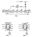
- Fig. 1 shows the block diagram of a conventional single quadrant drive with current control loop and speed control loop.
- the power section includes a thyristor converter 1 in a three-phase bridge circuit, commutation chokes 2, a direct current motor 3, an armature current sensor in the form of current transformers 4 arranged in the three-phase circuit and a speed sensor 5 in the form of a tachometer machine coupled to the direct current motor 3.
- the control and regulating part includes a six-pulse control set 6, a current regulator 7, a speed regulator 8 and a setpoint generator 9 in the form of a potentiometer, in a known function.
- the control set 6 is followed by an ignition pulse output stage 49 with distributor logic, which is used to generate the control pulses required for two successively current-carrying thyristors.
- this stage 49 there is also pulse coupling to the thyristor that was previously in the conductive state.
- Controlling a drive requires the command variable (setpoint) and the control variable (actual value) at the input of the controller.
- the reference variable (setpoint) is specified as DC voltage.
- the controlled variable (actual value), which is recorded with a sensor must be converted to a DC voltage suitable for the regulator input by means of a rectifier 10.
- the choice of the encoder is based on the requirements placed on the drive. With the usual mains voltages of 380/500 V or higher, it is advisable to galvanically separate the control and regulating circuit from the power circuit.
- the transducers used in drives are therefore generally isolated. In the case of fully controlled bridge circuits, the current can in principle be detected on the direct current or alternating current side.
- the normal AC converter as is generally used to connect AC measuring devices, is also suitable as a transmitter.
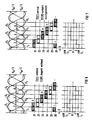
- Push-through current transformers which are commercially available and are used a lot for higher currents have a push-through opening 12 which is completely enclosed by the iron core 11.
- the primary winding which is also connected to the terminals, is not used, but a single or multiple primary current conductor, which is led through the through-opening 12 of the current transformer 4, for example, 6 times for 100 A nominal value of the primary current or 1 time for 600 A nominal value of the primary current is carried out in order to achieve the required nominal flooding of 600 AW, for example.
- the secondary winding 13 is usually designed for 5 A (1 A, 0.1 A) nominal current.
- a conductor e.g. S simple and a conductor e.g. R pushed through twice to form a feedback loop. Both conductors have the same defined push-through direction.
- the third conductor T is also guided outside the iron core 11 of the current transformer 4.
- the required AW ratio of 2: 1 according to the invention is achieved in that two conductors are simply pushed through, but in the case of one conductor half of the current is passed through the outside of the iron core 11 of the current transformer 4 through a shunt 15.
- this requires that the shunt 15 and the shunted conductor piece have the same impedance.
- another conversion constant must also be used here.
- the resulting flooding caused by current flow in the two inserted conductors generates an impressed current in the secondary winding 13 which flows through the connected load resistor 14.
- the course of the resulting floodings (AW) and the secondary currents proportional to them which are due to the invention Arrangement of the conductors and the conductor currents flowing in them are shown in the following figures.
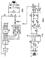
- FIG. 5 shows the known circuit diagram of a three-phase bridge circuit 16, which consists of the two three-pulse star circuits 17, 18. It has six thyristors 21-26, which are connected symmetrically to the phases R, S, T. The voltage star of the six voltages in succession at 60 ° is recorded below. The thyristors must be fired in this order. The numbers 21 - 26 on the voltage star, which correspond to the reference numbers for the thyristors, indicate this sequence.
- the timing of the firing pulses for the individual thyristors 21 - 26 is indicated, which are shown obliquely hatched, as well as the blocks of the thyristor currents flowing, these for a simplified explanation of the principle in a schematic form.
- the thyristor current blocks are highlighted according to their importance for the arrangement example according to FIG. 4 according to the invention.
- the single-acting current blocks are in the lead S and thus alternately in the thyristors 23 and 26 flow, characterized by horizontal hatching and the double-acting current blocks, which flow in the feed line R and thus alternately in the thyristors 21 and 24, by vertical hatching.
- the current blocks through the thyristors 22 and 25 are without influence.
- FIG. 6 shows the secondary current or AW ratios for the arrangement according to FIG. 4.
- the line is simple to construct on the basis of the information given above, it should be noted that the current blocks occurring when the current flows through the double-inserted conductor R and the thyristors 21 and 24 are highlighted vertically.
- the correction circuit according to FIG. 8 shows the burden resistor 14, which is connected to the secondary winding 13 of the current transformer 4 via a rectifier 10.
- the load resistor 14 is connected in parallel with a resistor 27 of the same size via a transistor 28 during the period of twice the AW number.
- the measuring current occurring with its double value is only available with a burden resistance with half the resulting ohmic value, so that the desired correction is made.
- the transistor 28 is controlled by a flip-flop 29 in the conductive state, which is set for the thyristor 22 or 25 by means of the non-coupled control pulse (low) is reset by means of the subsequent, non-coupled control pulse for the thyristor 23 or 26.
- control lines for the thyristors 22 and 25 are also connected to the inputs of an AND stage 30, the output of which is connected to the set input of the flip-flop 29.
- control lines for the thyristors 23 and 26 are also connected to the inputs of an AND stage 31, the output of which is connected to the reset input of the flip-flop 29.
- the rectification of the measuring current takes place in a known manner by means of the rectifier 10.
- a different sequence of the control pulses used to set and reset the flip-flop 29 must be used will. Of course, this also applies to an arrangement of the conductors according to FIG.
- the advantage of this circuit lies in the fact that the iron core 11 of the current transformer 4 is not magnetized twice as high in the case of the twice detected current, since in this case the resulting burden resistance 14
- the additional magnetization effort is only in Internal copper resistance of the secondary winding 13. As a result, no higher type power of the current transformer 4 is required.
- FIG. 9 A correction circuit with somewhat more complex electronics is shown in FIG. 9.
- an operational amplifier 32 makes it possible to load the current transformer 4 only with a very small burden voltage.
- An impedance converter 33 is connected downstream of the operational amplifier 32 in order to be able to use a type of low current carrying capacity for the operational amplifier 32.
- the burden voltage drops across the load resistor 34 and is rectified in a known circuit by means of a full-wave measuring rectifier or absolute value generator.
- Its first operational amplifier 35 which operates as an inverting rectifier, is connected to resistors 36 and 37, which have the same ohmic values as well as diodes 38 and 39.
- Its second operational amplifier 40 which operates as an inverting amplifier, is connected in the manner shown to the resistors 41-45 which have the same ohmic values.
- An electronic switch 46 can be used to switch its gain between its full and half value. This switch 46 is again controlled by the output signal of the flip-flop 29 shown in FIG. 8.
- the Zener diodes 47, 48 are used to derive the burden current and thus for overvoltage protection for the operational amplifier 32 in the event that 4 overvoltages occur in the secondary winding 13 of the current transformer, which are caused by highly dynamic processes in the primary circuit, for example by switching processes or short circuits.
- the advantage of this circuit is that the current transformer 4 practically works against the zero load voltage and therefore only a very small magnetizing current occurs.
- This circuit is therefore particularly suitable for Current actual value acquisition with downstream zero current signal via threshold switch is suitable. This is because the magnetizing current disturbing the zero current signal, which is known to cause the so-called. "Tail" of the demagnetization voltage delays the zero current signal, can be kept at a minimum value.
- the electronic correction circuit is not necessary for pure zero current reporting, for current or power measurements with pointer or digital instruments or for correlations with a large smoothing time constant, since in the first case only the zeroing of the current is of interest and in the other cases the through the error caused by the double current occurring in the display can be calibrated or compensated for.
Landscapes
- Engineering & Computer Science (AREA)
- Power Engineering (AREA)
- Measurement Of Current Or Voltage (AREA)
- Rectifiers (AREA)
- Ac-Ac Conversion (AREA)
- Transformers For Measuring Instruments (AREA)
Claims (1)
- Dispositif de transformation d'intensité pour des systèmes triphasés à trois conducteurs, notamment pour enregistrer la valeur effective d'intensité d'utilisateurs régulés de courant continu (3) alimentés par un convertisseur de courant, caractérisé en ce qu'il est prévu un seul transformateur d'intensité (4) sous la forme d'un transformateur d'intensité en connexion traversante, en ce que ce dernier est disposé côté courant triphasé et en ce que seulement deux des trois conducteurs de phase sont enfilés ou connectés à travers le transformateur d'intensité (4), en ce qu'afin d'éviter l'apparition d'un nombre résultant d'ampèretours de valeur zéro, les deux conducteurs de phase sont enfilés ou connectés à travers le transformateur d'intensité (4) avec la même direction définie de connexion traversante et un rapport de bobinage de 1:2, ou avec la même direction définie de connexion traversante et le même nombre de spires mais avec une valeur d'intensité diminuée de moitié dans un conducteur de phase par un shunt (15), ou avec le même nombre de spires mais des directions définies de connexion traversante mutuellement opposées, en ce que la valeur doublée de la tension de mesure, qui apparaît du côté secondaire par suite de la valeur ainsi doublée du nombre résultant d'ampèretours, est diminuée de moitié par un circuit de correction, et en ce que les ordres de connexion et de déconnexion du circuit de correction sont dérivés d'impulsions de commande pour les valves (21 à 26) du convertisseur de courant.
Applications Claiming Priority (2)
| Application Number | Priority Date | Filing Date | Title |
|---|---|---|---|
| AT539/89A AT393421B (de) | 1989-03-09 | 1989-03-09 | Stromwandleranordnung fuer dreileiter- drehstromsysteme zur stromistwerterfassung |
| AT539/89 | 1989-03-09 |
Publications (2)
| Publication Number | Publication Date |
|---|---|
| EP0453518A1 EP0453518A1 (fr) | 1991-10-30 |
| EP0453518B1 true EP0453518B1 (fr) | 1993-06-23 |
Family
ID=3493293
Family Applications (1)
| Application Number | Title | Priority Date | Filing Date |
|---|---|---|---|
| EP90903165A Expired - Lifetime EP0453518B1 (fr) | 1989-03-09 | 1990-02-16 | Transformateur de courant pour installation triphasee a trois conducteurs, en particulier pour la detection de la valeur effective de l'intensite pour un recepteur a courant continu regle, alimente par un redresseur |
Country Status (4)
| Country | Link |
|---|---|
| US (1) | US5202621A (fr) |
| EP (1) | EP0453518B1 (fr) |
| AT (2) | AT393421B (fr) |
| WO (1) | WO1990010940A1 (fr) |
Families Citing this family (18)
| Publication number | Priority date | Publication date | Assignee | Title |
|---|---|---|---|---|
| DE4106274A1 (de) * | 1991-02-28 | 1992-09-03 | Vacuumschmelze Gmbh | Stromsensor nach dem kompensationsprinzip |
| US5309349A (en) * | 1992-09-22 | 1994-05-03 | Industrial Technology Research Institute | Current detection method for DC to three-phase converters using a single DC sensor |
| US5710534A (en) * | 1995-04-25 | 1998-01-20 | Abb Power T&D Company Inc. | Electrical apparatus including electric field control means |
| US8692539B2 (en) * | 2006-11-30 | 2014-04-08 | Powersense A/S | Faraday effect current sensor |
| US8085009B2 (en) | 2007-08-13 | 2011-12-27 | The Powerwise Group, Inc. | IGBT/FET-based energy savings device for reducing a predetermined amount of voltage using pulse width modulation |
| US20110182094A1 (en) * | 2007-08-13 | 2011-07-28 | The Powerwise Group, Inc. | System and method to manage power usage |
| US8619443B2 (en) | 2010-09-29 | 2013-12-31 | The Powerwise Group, Inc. | System and method to boost voltage |
| US8085010B2 (en) | 2007-08-24 | 2011-12-27 | The Powerwise Group, Inc. | TRIAC/SCR-based energy savings device for reducing a predetermined amount of voltage using pulse width modulation |
| US8120307B2 (en) | 2007-08-24 | 2012-02-21 | The Powerwise Group, Inc. | System and method for providing constant loading in AC power applications |
| US8698447B2 (en) | 2007-09-14 | 2014-04-15 | The Powerwise Group, Inc. | Energy saving system and method for devices with rotating or reciprocating masses |
| US8810190B2 (en) * | 2007-09-14 | 2014-08-19 | The Powerwise Group, Inc. | Motor controller system and method for maximizing energy savings |
| US20090190378A1 (en) * | 2008-01-29 | 2009-07-30 | Hideo Ishii | Power supply device outputting pulsed electrical current |
| DE102008020371B4 (de) * | 2008-04-23 | 2019-11-14 | Kriwan Industrie-Elektronik Gmbh | Verfahren sowie Sensor-Messschaltung zum Überstromschutz eines Drehstromverbrauchers |
| EP2148210A1 (fr) * | 2008-07-21 | 2010-01-27 | PowerSense A/S | Ensemble de capteur de courant optique de Faraday en 3 phases |
| US8004255B2 (en) * | 2008-08-07 | 2011-08-23 | The Powerwise Group, Inc. | Power supply for IGBT/FET drivers |
| US8698446B2 (en) * | 2009-09-08 | 2014-04-15 | The Powerwise Group, Inc. | Method to save energy for devices with rotating or reciprocating masses |
| CA2771121C (fr) * | 2009-09-08 | 2018-05-15 | The Powerwise Group, Inc. | Systeme et procede d'economie d'energie pour dispositifs a masses rotatives ou animees d'un mouvement alternatif |
| DE102019209374A1 (de) * | 2019-06-27 | 2020-12-31 | Siemens Aktiengesellschaft | Stromsensor und Verfahren |
Family Cites Families (8)
| Publication number | Priority date | Publication date | Assignee | Title |
|---|---|---|---|---|
| DE1227136B (de) * | 1962-04-07 | 1966-10-20 | Siemens Ag | Anordnung zur Erzeugung einer Gleichspannung, die dem von einem Gleichrichter gelieferten Strom proportional ist |
| US3668513A (en) * | 1970-03-31 | 1972-06-06 | Tokyo Shibaura Electric Co | Upright type bushing current transformer |
| FR2106732A5 (fr) * | 1970-09-22 | 1972-05-05 | Alsthom | |
| US4096539A (en) * | 1976-08-31 | 1978-06-20 | Scaturro Angelo J | Detector of backfeed electrical currents |
| SU748528A1 (ru) * | 1978-02-03 | 1980-07-15 | Восточный научно-исследовательский институт по безопасности работ в горной промышленности | Трансформатор тока нулевой последовательности |
| JPS62141977A (ja) * | 1985-12-16 | 1987-06-25 | Toshiba Corp | プラズマ励起装置 |
| US4683513A (en) * | 1986-04-07 | 1987-07-28 | Westinghouse Electric Corp. | Dual current transformer current sensing method and sensor |
| DE3619801A1 (de) * | 1986-06-12 | 1987-12-17 | Leybold Heraeus Gmbh & Co Kg | Kurzschlussfeste stromversorgung fuer elektronenstrahlkanonen und aehnliche waehrend des betriebs bisweilen kurzschluesse erzeugende verbraucher |
-
1989
- 1989-03-09 AT AT539/89A patent/AT393421B/de not_active IP Right Cessation
-
1990
- 1990-02-16 AT AT90903165T patent/ATE91039T1/de not_active IP Right Cessation
- 1990-02-16 WO PCT/EP1990/000261 patent/WO1990010940A1/fr not_active Ceased
- 1990-02-16 US US07/752,565 patent/US5202621A/en not_active Expired - Fee Related
- 1990-02-16 EP EP90903165A patent/EP0453518B1/fr not_active Expired - Lifetime
Also Published As
| Publication number | Publication date |
|---|---|
| WO1990010940A1 (fr) | 1990-09-20 |
| US5202621A (en) | 1993-04-13 |
| ATA53989A (de) | 1991-03-15 |
| ATE91039T1 (de) | 1993-07-15 |
| EP0453518A1 (fr) | 1991-10-30 |
| AT393421B (de) | 1991-10-25 |
Similar Documents
| Publication | Publication Date | Title |
|---|---|---|
| EP0453518B1 (fr) | Transformateur de courant pour installation triphasee a trois conducteurs, en particulier pour la detection de la valeur effective de l'intensite pour un recepteur a courant continu regle, alimente par un redresseur | |
| DE2635965B2 (de) | Schaltungsanordnung und Verfahren zur Bildung einer elektrischen Größe, die einer Flußkomponente in einer Drehfeldmaschine proportional ist | |
| DE2130154B2 (de) | Einrichtung zum Nachbilden mindestens einer Gleichstromgröße | |
| DE4142342C2 (de) | Verfahren und Vorrichtung zur digitalen Strommessung | |
| DE1812926A1 (de) | Verfahren und Vorrichtung zur Messung des Schlupfes eines Asynchronmotors | |
| DE974154C (de) | Wandler fuer vorzugsweise kleine Gleichstromgroessen auf Magnetverstaerkergrundlage | |
| DE2554786C3 (de) | Schaltungsanordnung zum Steuern oder Regeln der Drehzahl eines elektrischen Motors | |
| DE1257959B (de) | Anordnung zur Messung eines wandernden veraenderlichen magnetischen Flusses | |
| DE3246329A1 (de) | Elektronisches ueberstromrelais | |
| DE3822051C2 (fr) | ||
| DE967625C (de) | Als Prozent- oder Sperrelais dienende Einrichtung | |
| EP0456868A1 (fr) | Dispositif pour la compensation d'erreur pour un compteur d'électricité à induction | |
| DE3939890C2 (fr) | ||
| DE2320229B2 (de) | Schaltungsanordnung zur galvanisch getrennten uebertragung einer gleichspannung | |
| DE3437610A1 (de) | Messverfahren und messeinrichtung fuer einen gleichstromsteller | |
| DE976469C (de) | Schaltungsanordnung zur Anzeige der Unsymmetrie bei Mehrphasen-Wechselstromsystemen | |
| DE527676C (de) | Vorrichtung zur Messung elektrischer Groessen und ihrer Summen am fernen Ort mit Hilfe von Wechselstrom | |
| DE1153452B (de) | Gleichstromwandler | |
| DE966572C (de) | Magnetischer Verstaerker | |
| DE3234053C2 (de) | Meßeinrichtung für den Momentanwert eines Stroms | |
| DE1663048B1 (de) | Regelanordnung zur Erzielung einer gleichmaessigen Belastung von statischen Wechselrichtern | |
| DE1172754B (de) | Steuergeraet fuer Synchronschalter | |
| DE712265C (de) | Vorrichtung zur Messung des in einer Leitung fliessenden Gleichstromes | |
| DE102020133983A1 (de) | Strommessumformer zum Messen des durch einen elektrischen Leiter fließenden Stroms und Verfahren zur Ausgabe der Stromstärke bei einem Strommessumformer mit Ausgabe der Energieflussrichtung bei Wechselströmen | |
| DE1268269B (de) | Verfahren zum Messen von Gleichstrom |
Legal Events
| Date | Code | Title | Description |
|---|---|---|---|
| PUAI | Public reference made under article 153(3) epc to a published international application that has entered the european phase |
Free format text: ORIGINAL CODE: 0009012 |
|
| 17P | Request for examination filed |
Effective date: 19910709 |
|
| AK | Designated contracting states |
Kind code of ref document: A1 Designated state(s): AT DE IT |
|
| 17Q | First examination report despatched |
Effective date: 19920825 |
|
| RAP1 | Party data changed (applicant data changed or rights of an application transferred) |
Owner name: SIEMENS AKTIENGESELLSCHAFT OESTERREICH |
|
| GRAA | (expected) grant |
Free format text: ORIGINAL CODE: 0009210 |
|
| AK | Designated contracting states |
Kind code of ref document: B1 Designated state(s): AT DE IT |
|
| PG25 | Lapsed in a contracting state [announced via postgrant information from national office to epo] |
Ref country code: IT Free format text: LAPSE BECAUSE OF FAILURE TO SUBMIT A TRANSLATION OF THE DESCRIPTION OR TO PAY THE FEE WITHIN THE PRESCRIBED TIME-LIMIT;WARNING: LAPSES OF ITALIAN PATENTS WITH EFFECTIVE DATE BEFORE 2007 MAY HAVE OCCURRED AT ANY TIME BEFORE 2007. THE CORRECT EFFECTIVE DATE MAY BE DIFFERENT FROM THE ONE RECORDED. Effective date: 19930623 |
|
| REF | Corresponds to: |
Ref document number: 91039 Country of ref document: AT Date of ref document: 19930715 Kind code of ref document: T |
|
| REF | Corresponds to: |
Ref document number: 59001863 Country of ref document: DE Date of ref document: 19930729 |
|
| PLBE | No opposition filed within time limit |
Free format text: ORIGINAL CODE: 0009261 |
|
| STAA | Information on the status of an ep patent application or granted ep patent |
Free format text: STATUS: NO OPPOSITION FILED WITHIN TIME LIMIT |
|
| 26N | No opposition filed | ||
| PGFP | Annual fee paid to national office [announced via postgrant information from national office to epo] |
Ref country code: AT Payment date: 20060118 Year of fee payment: 17 |
|
| PGFP | Annual fee paid to national office [announced via postgrant information from national office to epo] |
Ref country code: DE Payment date: 20060424 Year of fee payment: 17 |
|
| PG25 | Lapsed in a contracting state [announced via postgrant information from national office to epo] |
Ref country code: AT Free format text: LAPSE BECAUSE OF NON-PAYMENT OF DUE FEES Effective date: 20070216 |
|
| PG25 | Lapsed in a contracting state [announced via postgrant information from national office to epo] |
Ref country code: DE Free format text: LAPSE BECAUSE OF NON-PAYMENT OF DUE FEES Effective date: 20070901 |