EP0456868A1 - Dispositif pour la compensation d'erreur pour un compteur d'électricité à induction - Google Patents
Dispositif pour la compensation d'erreur pour un compteur d'électricité à induction Download PDFInfo
- Publication number
- EP0456868A1 EP0456868A1 EP90109385A EP90109385A EP0456868A1 EP 0456868 A1 EP0456868 A1 EP 0456868A1 EP 90109385 A EP90109385 A EP 90109385A EP 90109385 A EP90109385 A EP 90109385A EP 0456868 A1 EP0456868 A1 EP 0456868A1
- Authority
- EP
- European Patent Office
- Prior art keywords
- current
- compensation
- dependent
- electricity meter
- error
- Prior art date
- Legal status (The legal status is an assumption and is not a legal conclusion. Google has not performed a legal analysis and makes no representation as to the accuracy of the status listed.)
- Withdrawn
Links
- 230000005611 electricity Effects 0.000 title claims abstract description 20
- 230000006698 induction Effects 0.000 title claims abstract description 9
- 230000001419 dependent effect Effects 0.000 claims abstract description 15
- 238000004804 winding Methods 0.000 claims abstract description 7
- 235000000396 iron Nutrition 0.000 claims abstract description 6
- 230000006870 function Effects 0.000 claims description 5
- XEEYBQQBJWHFJM-UHFFFAOYSA-N Iron Chemical compound [Fe] XEEYBQQBJWHFJM-UHFFFAOYSA-N 0.000 description 9
- 238000010586 diagram Methods 0.000 description 4
- 229910052742 iron Inorganic materials 0.000 description 4
- 238000013016 damping Methods 0.000 description 3
- 238000005516 engineering process Methods 0.000 description 2
- 230000006978 adaptation Effects 0.000 description 1
- 239000003990 capacitor Substances 0.000 description 1
- 230000007423 decrease Effects 0.000 description 1
- 238000000605 extraction Methods 0.000 description 1
- 230000004907 flux Effects 0.000 description 1
- 238000009499 grossing Methods 0.000 description 1
- 230000005612 types of electricity Effects 0.000 description 1
Images


Classifications
-
- G—PHYSICS
- G01—MEASURING; TESTING
- G01R—MEASURING ELECTRIC VARIABLES; MEASURING MAGNETIC VARIABLES
- G01R11/00—Electromechanical arrangements for measuring time integral of electric power or current, e.g. of consumption
- G01R11/02—Constructional details
- G01R11/17—Compensating for errors; Adjusting or regulating means therefor
- G01R11/23—Compensating for errors caused by friction, e.g. adjustment in the light load range
-
- G—PHYSICS
- G01—MEASURING; TESTING
- G01R—MEASURING ELECTRIC VARIABLES; MEASURING MAGNETIC VARIABLES
- G01R11/00—Electromechanical arrangements for measuring time integral of electric power or current, e.g. of consumption
- G01R11/02—Constructional details
- G01R11/17—Compensating for errors; Adjusting or regulating means therefor
- G01R11/21—Compensating for errors caused by damping effects of the current, e.g. adjustment in the overload range
-
- G—PHYSICS
- G01—MEASURING; TESTING
- G01R—MEASURING ELECTRIC VARIABLES; MEASURING MAGNETIC VARIABLES
- G01R21/00—Arrangements for measuring electric power or power factor
- G01R21/133—Arrangements for measuring electric power or power factor by using digital technique
-
- G—PHYSICS
- G01—MEASURING; TESTING
- G01R—MEASURING ELECTRIC VARIABLES; MEASURING MAGNETIC VARIABLES
- G01R35/00—Testing or calibrating of apparatus covered by the other groups of this subclass
- G01R35/04—Testing or calibrating of apparatus covered by the other groups of this subclass of instruments for measuring time integral of power or current
Definitions
- the invention relates to an error compensation arrangement for an electricity meter according to the induction principle according to the preamble of claim 1.
- Electricity meters of this type are described, for example, in the textbook “Fundamentals of Meter Technology", Julius Springer-Verlag, Berlin, 1930, pages 136 to 197. These meters have a so-called voltage iron with a voltage coil to which the mains voltage is applied, and a so-called current iron with a current coil through which the load current flows. Both coils are arranged on an iron core with an air gap and act on a rotatable, magnetically braked rotor disc, which dips into the air gaps of the voltage and current iron and whose magnetic fluxes exert a torque on the disc so that it has a removal capacity dependent speed rotates about its axis of rotation. The speed is determined by a counter and immediately shows the electrical work corresponding to the extraction capacity in kWh.
- each electricity meter of the type described above has a characteristic error, the size of which is determined by the bearing friction of the rotor disk at low load current and by the size of the so-called current damping with increasing load current.
- the invention has for its object the load current-dependent occurring in an electricity meter of the type mentioned Compensate for errors as completely as possible.
- the meter-specific error curve is represented in the form of load current-dependent error values and is transformed with the aid of a control unit into load current-dependent control variables which compensate for the torque exerted on the rotor disk in an error-dependent manner via a compensation circuit.
- the error curve correction according to claim 2 can be simplified in such a way that the auxiliary windings are connected via a multiphase rectifier system to a direct current circuit which serves as a compensation circuit.
- the compensation with digital means is effected by a microcomputer as a control device, in whose memory the error curve of the counter in question is stored in digital form.
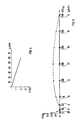
- the typical error curve 1 of an electricity meter according to the induction principle (Ferraris meter) shown in FIG. 1 shows the percentage error F as a function of the percentage load current I of the nominal current I N. From this it can be seen that the percentage error only reaches zero in three points. In the area of load currents I ⁇ I N, the error curve is essentially caused by the friction of the rotor disk of the meter and, in the case of larger load currents, by the so-called current damping, which is essentially proportional to the square of the load current. The current damping is noticeable at load currents from approximately 50% of the nominal current upwards and leads to an increase in the percentage error up to a value of the load current of approximately 300% of the nominal current and then decreases continuously.
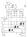
- the position of this error curve in relation to the zero error straight line can be determined by a circuit arrangement shown in FIG. 2 move parallel.
- the voltage irons 2, 3, 4 of a schematically illustrated three-phase electricity meter 5 are provided with auxiliary windings 6, 7, 8.
- Each of these auxiliary windings is connected to a multi-phase rectifier arrangement 9, the output-side DC circuit of which is closed as a compensation circuit via an adjustable electrical load in the form of a load resistor 10 and a smoothing capacitor 11 connected in parallel therewith.
- the size of the burden resistor 10 can be set by a control unit 12 as a function of the load current I drawn from the three-phase network RST by a consumer 16 via the current iron 13, 14, 15 of the electricity meter 5.
- a group of error curves F1, F2, F3, F4 with different electrical burdens or compensation current quantities I K is shown as a parameter.
- the error curve F 1 corresponds to the error curve 1 from FIG. 1. From this it can be seen that the error curves experience a parallel shift when choosing compensation currents I K of different sizes. It follows from this that a corresponding error in the size of the compensation current can be used to determine a zero error point for each individual value of the load current I.
- a prerequisite for such complete error compensation is that the compensation current quantities are correctly assigned to the error curve F.
- an embodiment in digital technology is more expedient.
- a microcomputer is suitable for this purpose, in the memory of which the compensation current values assigned to the relevant load current values are entered and stored in the form of software. This makes it possible to make do with a single hardware configuration, the function of which can be specified individually for each meter using software. The accuracy depends on the density of the compensation values.
- the control of the compensation current I K can then be done in different ways, for example by directly varying the size of the load resistor 10 or, as shown in FIG. 6, with a constant load resistor 19 using an electronic switch 20, the load resistor 19 by starting pulses of different lengths , depending on the size of the control pulse frequency P / s pulse pause duration in the fault circuit.
- a particularly inexpensive embodiment is obtained when an electronic tariff device is assigned to the electricity meter based on the induction principle.
- This usually has a microcomputer that can be used for the prescribed purpose.
Landscapes
- Physics & Mathematics (AREA)
- General Physics & Mathematics (AREA)
- Engineering & Computer Science (AREA)
- Power Engineering (AREA)
- Control Of Ac Motors In General (AREA)
- Tests Of Circuit Breakers, Generators, And Electric Motors (AREA)
Priority Applications (2)
| Application Number | Priority Date | Filing Date | Title |
|---|---|---|---|
| EP90109385A EP0456868A1 (fr) | 1990-05-17 | 1990-05-17 | Dispositif pour la compensation d'erreur pour un compteur d'électricité à induction |
| KR1019910007910A KR910020446A (ko) | 1990-05-17 | 1991-05-16 | 유도원리에 따른 전력계의 에러보상장치 |
Applications Claiming Priority (1)
| Application Number | Priority Date | Filing Date | Title |
|---|---|---|---|
| EP90109385A EP0456868A1 (fr) | 1990-05-17 | 1990-05-17 | Dispositif pour la compensation d'erreur pour un compteur d'électricité à induction |
Publications (1)
| Publication Number | Publication Date |
|---|---|
| EP0456868A1 true EP0456868A1 (fr) | 1991-11-21 |
Family
ID=8203994
Family Applications (1)
| Application Number | Title | Priority Date | Filing Date |
|---|---|---|---|
| EP90109385A Withdrawn EP0456868A1 (fr) | 1990-05-17 | 1990-05-17 | Dispositif pour la compensation d'erreur pour un compteur d'électricité à induction |
Country Status (2)
| Country | Link |
|---|---|
| EP (1) | EP0456868A1 (fr) |
| KR (1) | KR910020446A (fr) |
Cited By (4)
| Publication number | Priority date | Publication date | Assignee | Title |
|---|---|---|---|---|
| RU2474834C1 (ru) * | 2011-09-09 | 2013-02-10 | Олег Фёдорович Меньших | Схема контроля чувствительности трехфазных электронных приборов учета электроэнергии |
| CN108152782A (zh) * | 2017-12-05 | 2018-06-12 | 国家电网公司 | 一种高供高计电能表更正系数的测试方法 |
| CN110568397A (zh) * | 2019-08-12 | 2019-12-13 | 浙江恒业电子有限公司 | 一种基于mcu软件的电能表校正方法及系统 |
| CN118444239A (zh) * | 2024-07-08 | 2024-08-06 | 武汉阿迪克电子股份有限公司 | 一种智能电能表的电表计量方法及智能电能表 |
Citations (4)
| Publication number | Priority date | Publication date | Assignee | Title |
|---|---|---|---|---|
| US2412070A (en) * | 1944-03-18 | 1946-12-03 | Walter C Wagner | Secondary meter for primary energy |
| DE2461259A1 (de) * | 1974-12-23 | 1976-07-01 | Siemens Ag | Fotoelektrische abtastvorrichtung fuer elektrizitaetszaehler |
| DE3514371A1 (de) * | 1985-05-28 | 1986-10-23 | Mitsubishi Denki K.K., Tokio/Tokyo | Elektronischer energiezaehler fuer elektrische energie |
| WO1990000740A1 (fr) * | 1988-07-15 | 1990-01-25 | Sangamo Weston, Inc. | Circuit de reglage et procede pour compteur d'energie electrique a semi-conducteurs |
-
1990
- 1990-05-17 EP EP90109385A patent/EP0456868A1/fr not_active Withdrawn
-
1991
- 1991-05-16 KR KR1019910007910A patent/KR910020446A/ko not_active Withdrawn
Patent Citations (4)
| Publication number | Priority date | Publication date | Assignee | Title |
|---|---|---|---|---|
| US2412070A (en) * | 1944-03-18 | 1946-12-03 | Walter C Wagner | Secondary meter for primary energy |
| DE2461259A1 (de) * | 1974-12-23 | 1976-07-01 | Siemens Ag | Fotoelektrische abtastvorrichtung fuer elektrizitaetszaehler |
| DE3514371A1 (de) * | 1985-05-28 | 1986-10-23 | Mitsubishi Denki K.K., Tokio/Tokyo | Elektronischer energiezaehler fuer elektrische energie |
| WO1990000740A1 (fr) * | 1988-07-15 | 1990-01-25 | Sangamo Weston, Inc. | Circuit de reglage et procede pour compteur d'energie electrique a semi-conducteurs |
Non-Patent Citations (2)
| Title |
|---|
| IEEE TRANSACTIONS ON POWER DELIVERY, Band PWRD-2, Nr. 4, Oktober 1987, Seiten 1018-1024; E. SO: "A current-comparator-based wattmeter for high voltage power measurements at very low power factors" * |
| JOURNAL OF PHYSICS E-SCIENTIFIC INSTRUMENTS, Band 14, Nr. 7, Juli 1981, Seiten 777-782; H.M.J.M. DORTMANS: "Application of microprocessors" * |
Cited By (4)
| Publication number | Priority date | Publication date | Assignee | Title |
|---|---|---|---|---|
| RU2474834C1 (ru) * | 2011-09-09 | 2013-02-10 | Олег Фёдорович Меньших | Схема контроля чувствительности трехфазных электронных приборов учета электроэнергии |
| CN108152782A (zh) * | 2017-12-05 | 2018-06-12 | 国家电网公司 | 一种高供高计电能表更正系数的测试方法 |
| CN110568397A (zh) * | 2019-08-12 | 2019-12-13 | 浙江恒业电子有限公司 | 一种基于mcu软件的电能表校正方法及系统 |
| CN118444239A (zh) * | 2024-07-08 | 2024-08-06 | 武汉阿迪克电子股份有限公司 | 一种智能电能表的电表计量方法及智能电能表 |
Also Published As
| Publication number | Publication date |
|---|---|
| KR910020446A (ko) | 1991-12-20 |
Similar Documents
| Publication | Publication Date | Title |
|---|---|---|
| DE2658321C2 (de) | Regelanordnung für einen kollektorlosen Gleichstrommotor | |
| EP0047900B1 (fr) | Procédé et dispositif pour déterminer la résistance du rotor d'une machine asynchrone électrique | |
| DE2348667B2 (de) | Elektronischer kWh-Zähler | |
| DE3736303C2 (fr) | ||
| DE10337282B4 (de) | Messgeräteeinheit mit einem Magnetzeiger-Positionsdetektor | |
| EP0453518B1 (fr) | Transformateur de courant pour installation triphasee a trois conducteurs, en particulier pour la detection de la valeur effective de l'intensite pour un recepteur a courant continu regle, alimente par un redresseur | |
| DE2635965C3 (de) | Schaltungsanordnung und Verfahren zur Bildung einer elektrischen Größe, die einer Flußkomponente in einer Drehfeldmaschine proportional ist | |
| DE3524001C2 (fr) | ||
| EP0456868A1 (fr) | Dispositif pour la compensation d'erreur pour un compteur d'électricité à induction | |
| DE69602885T2 (de) | Geschwindigkeitsregler für einen sensorlosen Motor | |
| DE3826551C2 (de) | Vorrichtung zur Leistungsfaktormessung | |
| DE3203257A1 (de) | Vorrichtung zum bestimmen der gemeinsamen frequenz zweier unabhaengig veraenderlicher wechselgroessen, insbesondere bei einer drehfeldmaschine | |
| EP1460438A1 (fr) | Compteur d'électricité modulaire | |
| DE974154C (de) | Wandler fuer vorzugsweise kleine Gleichstromgroessen auf Magnetverstaerkergrundlage | |
| AT149619B (de) | Verfahren zum Messen, Aufschreiben und Regeln physikalischer Größen. | |
| DE2620992C2 (de) | Einrichtung zur maschinenspannungssynchronisierten Zündung der Wechselrichterventile eines Stromrichtermotors | |
| DE527676C (de) | Vorrichtung zur Messung elektrischer Groessen und ihrer Summen am fernen Ort mit Hilfe von Wechselstrom | |
| DE290914C (fr) | ||
| DE1638523B2 (de) | Verfahren zur justierung der von einem wechselstromgenerator mit permanentmagnetlaeufer gelieferten spannung | |
| AT20920B (de) | Vorrichtung zur Einstellung von Motor-Ampèrestundenzählern für verschiedene Spannungen. | |
| DE663256C (de) | Anordnung zur Regelung und Konstanthaltung von Zaehlereichstationen oder anderen Messeinrichtungen zugefuehrten elektrischen Groessen | |
| DE2260441B2 (de) | Analog-digital-wandler | |
| DE701520C (de) | Einrichtung zur Ermittlung der Phasenlage des einer unsymmetrischen Belastung entsprechenden Gegensystemvektors | |
| DE322500C (fr) | ||
| DE3939890C2 (fr) |
Legal Events
| Date | Code | Title | Description |
|---|---|---|---|
| PUAI | Public reference made under article 153(3) epc to a published international application that has entered the european phase |
Free format text: ORIGINAL CODE: 0009012 |
|
| 17P | Request for examination filed |
Effective date: 19901205 |
|
| AK | Designated contracting states |
Kind code of ref document: A1 Designated state(s): AT CH DE DK FR GB IT LI SE |
|
| STAA | Information on the status of an ep patent application or granted ep patent |
Free format text: STATUS: THE APPLICATION IS DEEMED TO BE WITHDRAWN |
|
| 18D | Application deemed to be withdrawn |
Effective date: 19931201 |