EP0453548B1 - Imprimante compacte amelioree ayant des selections des feuilles et des milieux tracteurs - Google Patents
Imprimante compacte amelioree ayant des selections des feuilles et des milieux tracteurs Download PDFInfo
- Publication number
- EP0453548B1 EP0453548B1 EP90917110A EP90917110A EP0453548B1 EP 0453548 B1 EP0453548 B1 EP 0453548B1 EP 90917110 A EP90917110 A EP 90917110A EP 90917110 A EP90917110 A EP 90917110A EP 0453548 B1 EP0453548 B1 EP 0453548B1
- Authority
- EP
- European Patent Office
- Prior art keywords
- sheet
- media
- tractor
- platen
- Prior art date
- Legal status (The legal status is an assumption and is not a legal conclusion. Google has not performed a legal analysis and makes no representation as to the accuracy of the status listed.)
- Expired - Lifetime
Links
- 238000011093 media selection Methods 0.000 title 1
- 230000000694 effects Effects 0.000 claims description 3
- 230000000903 blocking effect Effects 0.000 claims 1
- 230000001360 synchronised effect Effects 0.000 claims 1
- 238000010276 construction Methods 0.000 description 3
- 125000004122 cyclic group Chemical group 0.000 description 1
- 230000009977 dual effect Effects 0.000 description 1
- 230000002093 peripheral effect Effects 0.000 description 1
Images
Classifications
-
- B—PERFORMING OPERATIONS; TRANSPORTING
- B41—PRINTING; LINING MACHINES; TYPEWRITERS; STAMPS
- B41J—TYPEWRITERS; SELECTIVE PRINTING MECHANISMS, i.e. MECHANISMS PRINTING OTHERWISE THAN FROM A FORME; CORRECTION OF TYPOGRAPHICAL ERRORS
- B41J11/00—Devices or arrangements of selective printing mechanisms, e.g. ink-jet printers or thermal printers, for supporting or handling copy material in sheet or web form
- B41J11/48—Apparatus for condensed record, tally strip, or like work using two or more papers, or sets of papers, e.g. devices for switching over from handling of copy material in sheet form to handling of copy material in continuous form and vice versa or point-of-sale printers comprising means for printing on continuous copy material, e.g. journal for tills, and on single sheets, e.g. cheques or receipts
-
- B—PERFORMING OPERATIONS; TRANSPORTING
- B41—PRINTING; LINING MACHINES; TYPEWRITERS; STAMPS
- B41J—TYPEWRITERS; SELECTIVE PRINTING MECHANISMS, i.e. MECHANISMS PRINTING OTHERWISE THAN FROM A FORME; CORRECTION OF TYPOGRAPHICAL ERRORS
- B41J29/00—Details of, or accessories for, typewriters or selective printing mechanisms not otherwise provided for
- B41J29/02—Framework
- B41J29/026—Stackable
Definitions
- the present invention relates to compact printers capable of printing with either continuous, edge perforated print media (commonly referred to as tractor media) or sheet media and, more specifically to an improved media feeding and guiding system for enabling the printer to operate selectively in either of such sheet or tractor media modes.
- U.S. Patent 4,725,857 discloses a compact printer having a unique integral sheet feeding system that is interchangably operative with a continuous, edge perforated tractor media feeding system. Both feeding systems share a feeder-platen member which moves the media from a region near the bottom of the printer housing through the print zone and out through the top of the housing. Sheet feed is effected by providing cyclic feed contacts between the top sheet of a supply station stack and a friction surface(s) on the feeder-platen.
- a control lever is moved to disengage the sheet supply from the feeder-platen and to open the passage for tractor media to be fed above the sheet media stack, into the printing region, where it can be positioned on pins on the ends of the feeder-platen that cooperate with the perforations of the tractor media.
- US-A-4,452,543 discloses a printer having multiple paths to accommodate cut paper sheets, manually fed paper and continuous forms for supply to a cylindrical platen such that the printer can be utilized with various types and sizes of paper.
- the printer includes a bail mechanism operable to capture the cut paper sheets and the manually fed sheets and to be moved to a displaced position when the printer is used for continuous forms.
- the provision of the tractor media pins on the feeder-platen presents difficulties.
- the protruding pins on the feeder-platen can block the passage of "end” print heads, which is necessary to allow "central” print heads to cover the full scan line distance.
- This problem can be solved by retractable pins or pivoting print heads, but those solutions are not desirable because of their mechanical complexities.
- One important object of the present invention is to provide for a compact printer having an integral sheet feeding system, a cooperative system for guiding and feeding tractor media that avoids the problems noted above.
- one advantage of the present invention is that its tractor media engagement structures do not impede print head traverse.
- a further advantage of the present invention is that, in systems according to the present invention, the tractor engagement structures can be readily adjusted for varying paper widths.
- Another advantage of the present invention is that its construction allows a common feeder-platen drive for both sheet and tractor media, but allows tractor media feed control structures to override the feeder-platen drive, when necessary.
- a printer having a print media handling system as defined in Claim 1.
- the present invention constitutes an improved print media handling system for a compact printer of the kind having a housing, a cut-sheet supply station formed in the lower portion of the housing and a rotatable print platen constructed and located to feed top sheets from the supply station through a print path ingress, past a print zone and out a print path egress formed in the upper portion of the housing.
- Such media handling system includes a supply station mounted for movement to and from a sheet engaging relation with respect to the print platen; a device for selectively controlling such movement of the supply station; a tractor media inlet passage into the housing, under the platen and to the print path ingress; a pair of feed control wheels constructed and mounted for unitary rotation in engagement with tractor media along the media inlet passage; bail rollers engaging the platen between the print path ingress and egress; a spring system for urging the bail rollers to drive relations with the platen; and a spring control device for Varying the urging force between different sheet and tractor media conditions.
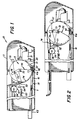
- FIGS. 1 and 2 are shown in its tractor media and sheet media orientations.
- the printer comprises a housing 11 which substantially encloses a print head carriage assembly 12, a feeder-platen assembly 13, a sheet media supply station assembly 14 and a tractor media feed control assembly 15.
- the print head carriage assembly 12 can be of the kind described in U.S. Patent 4,709,245 and comprise a plurality of nests 21 adapted to receive and operatively position print/cartridges 22.
- the carriage assembly includes drive means (not shown) for traversing the nests 21 along support rail 23 to print successive line portions of print media moved through a print zone by the feeder-platen assembly 13.
- the feeder platen assembly comprises a feeder-platen 31 rotatably mounted so that its periphery passes a media supply region, the print zone and a media egress region. It preferably has frictional surface portions 32 for feeding sheets from the printer supply as described in U.S. Patent 4,763,138.
- the sheet media supply station assembly 14 comprises a force plate element 41 movably mounted in the bottom of the printer and urged toward the feeding-platen 31 by a force plate spring 42.
- a drawer 43 in the rear of the printer can be provided to load a sheet stack S onto the force plate as described in U.S. patent 4,783,669.
- the tractor media feed control assembly 15 comprises two subassemblies.
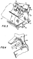
- a pair of guide members 51, 52 extend from the top of the printer, down to a location above a supported sheet stack so that the lead end of the tractor media can be inserted beneath the feeder platen 31 and up through the print zone to a position for commencement of print operation.
- the second subassembly comprises a pair of feed control wheels 54, that are keyed to a shaft 56.
- the shaft has end extensions (not shown) mounted in the housing 11 so that the shaft and its keyed wheels can rotate as an integral unit.
- Each guide wheel has a plurality of tracking pins 57 spaced around its periphery with a pitch that matches the perforations pitch in tractor media.
- slotted cover members 58 can be supported in the printer to pivot on hinges 59 and hold tractor media on the pins of wheels 54.
- the wheels and the cover members can be slidable along the direction of the length of shaft 56 to accommodate different widths of media.
- the shaft 56 is mounted in the printer in a manner providing a frictional drag to its rotation, but is otherwise non-driven, or in an idler mode.
- a bail roller assembly cooperates with the structures just described and a movable mode control member 70 to provide a higher nip pressure between the bail roller and the feeder-platen in sheet feed mode and a lower nip pressure in the tractor media mode.
- This is desirable because the sheet feed mode relies on non-slippage at the nip to maintain lateral tracking of a sheet, while the tractor media mode relies on the drag forces of guide wheels 54 to maintain tracking, and thus needs a slippable condition at the bail roller nip to allow the guide wheels to dominate.
- bail rollers 61 are mounted for movement toward and away from the feeder platen (in a conventional fashion) but are urged toward the feeder-platen by a spring assembly comprising cables 62 and springs 63, coupled to housing 11. As shown in FIGS. 1 and 2, the cables extends over a path defined by fixed constraint members 64 and constraint member 75 which is mounted on, and movable with, mode control members 70.
- mode control member 70 other than those of constraint member 75, are described in detail in U.S. Patent 4,725,857.
- this member is mounted in the printer housing for rotation on mount pin 72 and includes a cam member 73, guide teeth portions 74 and operating lever 76 on which constraint member 75 is formed.
- rotation of the mode control member 70 to the FIG. 1 position causes the cam surface 73 to engage tab 41a of force plate 41 and depress the sheet stack S.
- This rotation also moves teeth guides 74 in a position for directing tractor media between the stack S and feeder platen 31. Movement of the mode control lever to the FIG. 2 position allows force plate 41 to move up so sheets thereon can be engaged by the feeder platen and moves teeth 74 to block the tractor media ingress.
- the movement of the mode control member 70 between the FIG. 1 and FIG. 2 conditions also adjusts the nip pressure of bail roller 61 to that appropriate for tractor media or sheet media operation.
- tractor media, printer mode the constraint provides a relatively shorter cable path from bail rollers 61 to springs 64. This provides a relatively lower nip pressure at the bail roller to allow tractor media to be loaded and fed under control of the guide wheels 54.
- sheet media, printer mode the constraint member 75 lengthens the cable path from bail rollers 61 to springs 63 and provides a relatively higher nip pressure for sheet and print operations.
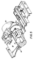
- FIG. 5 shows an alternative preferred embodiment of the present invention wherein the feed control wheels 80 are driven with a slightly lower peripheral speed than the platen 13'.
- wheels 80 are driven through gear train 81, 82 (coupled to motor drive 85).
- the feed control system comprising wheels 80 and their drive perform similarly to the previously described embodiments, providing controlled drag on media feed at the nip of bail rollers 61' and feed-platen 13'.
- the same spring assembly as described previously is provided to control the pressure at the bail roller nip so that tractor media can slip and allow guide wheels 80 to effect feed control.
- FIG. 5 shows an alternative preferred embodiment of the present invention wherein the feed control wheels 80 are driven with a slightly lower peripheral speed than the platen 13'.
- a single plate 90 hinged at mountings 92, is pivotable to allow tractor paper to be inserted and then closed as shown in FIG. 5 to retain the engagement of media perforations on pins of wheels 80.
- the under surface of plate 90 has guide members 93 which perform like elements 51 in the previous embodiments.
- the present invention has advantageous industrial utility in providing a simple mechanical construction for enabling reliable printer transport of sheet and tractor media, selectively.
Landscapes
- Handling Of Sheets (AREA)
Abstract
Claims (5)
- Imprimante (10) comprenant un boîtier (11), un poste (14) d'alimentation en feuille coupée, un rouleau rotatif d'impression (13, 31) dont la construction et le positionnement sont tels qu'il fait avancer la feuille coupée supérieure du poste d'alimentation par une entrée d'un trajet d'impression, le long d'une zone d'impression et vers l'extérieur par une sortie d'un trajet d'impression, et un système de gestion de supports d'impression qui est ajustable entre des modes d'avance de feuille coupée et d'avance d'un support d'impression pour organe de traction, et qui comprend :
un dispositif (70, 73) de commande de mode destiné à commander sélectivement le poste d'alimentation afin qu'il permette le fonctionnement avec des feuilles coupées ou des supports pour organe de traction,
un dispositif (51, 52) formant un passage d'entrée pour support pour organe de traction dans le boîtier, sous le rouleau d'impression (31) et vers l'entrée du trajet d'impression,
une paire de roues (54) de commande d'alimentation dont la construction et le montage sont tels qu'elles peuvent tourner ensemble et coopérer avec le support pour organe de traction le long du passage d'entrée en appliquant à celui-ci une force de frottement, et
des rouleaux (61 ; 61') d'anse coopérant avec le rouleau d'impression (31) entre l'entrée et la sortie du trajet d'impression,
le système de gestion de supports d'impression étant caractérisé par :
un dispositif à ressort (62 ; 63) destiné à repousser les rouleaux d'anse (61 ; 61') avec une pression élevée ou faible dans la zone de serrage contre le rouleau d'impression (31), et
un dispositif (75, 76) de commande de ressort commandé par le dispositif (70) de commande de mode et destiné à faire varier le dispositif à ressort (62, 63) afin qu'il applique la pression élevée en mode d'avance de feuille coupée et la pression faible en mode d'avance du support pour organe de traction. - Imprimante selon la revendication 1, dans laquelle le dispositif (75, 76) de commande de ressort est couplé au dispositif (73) de commande de poste d'alimentation afin qu'ils travaillent en synchronisme.
- Imprimante selon la revendication 2, dans laquelle le dispositif (75, 76) de commande de ressort provoque une réduction de la pression dans la zone de serrage lors du déplacement du poste (14) d'alimentation en feuilles coupées vers la position de contact avec la feuille coupée.
- Imprimante selon la revendication 2, comprenant en outre un dispositif (74), commandé par le dispositif (73) de commande de poste d'impression et destiné à boucher et déboucher sélectivement le passage d'entrée du support pour organe de traction.
- Imprimante selon la revendication 1, dans laquelle le dispositif de gestion de supports d'impression est en outre caractérisé par un dispositif (41, 41a, 43) de montage du poste d'alimentation (14) afin qu'il se déplace vers la position de contact et à partir de la position de contact par rapport au rouleau d'impression (31).
Applications Claiming Priority (3)
| Application Number | Priority Date | Filing Date | Title |
|---|---|---|---|
| US07/435,108 US5129748A (en) | 1989-11-13 | 1989-11-13 | Compact printer having sheet and tractor media selections |
| US435108 | 1989-11-13 | ||
| PCT/US1990/006378 WO1991007284A1 (fr) | 1989-11-13 | 1990-11-05 | Imprimante compacte amelioree ayant des selections des feuilles et des milieux tracteurs |
Publications (2)
| Publication Number | Publication Date |
|---|---|
| EP0453548A1 EP0453548A1 (fr) | 1991-10-30 |
| EP0453548B1 true EP0453548B1 (fr) | 1994-08-31 |
Family
ID=23727019
Family Applications (1)
| Application Number | Title | Priority Date | Filing Date |
|---|---|---|---|
| EP90917110A Expired - Lifetime EP0453548B1 (fr) | 1989-11-13 | 1990-11-05 | Imprimante compacte amelioree ayant des selections des feuilles et des milieux tracteurs |
Country Status (5)
| Country | Link |
|---|---|
| US (1) | US5129748A (fr) |
| EP (1) | EP0453548B1 (fr) |
| JP (1) | JP3040814B2 (fr) |
| DE (1) | DE69012099T2 (fr) |
| WO (1) | WO1991007284A1 (fr) |
Families Citing this family (3)
| Publication number | Priority date | Publication date | Assignee | Title |
|---|---|---|---|---|
| JPH05124276A (ja) * | 1991-10-31 | 1993-05-21 | Brother Ind Ltd | 印字装置 |
| JP3098369B2 (ja) * | 1993-12-15 | 2000-10-16 | キヤノン株式会社 | シート給送装置及び記録装置 |
| US6739683B2 (en) * | 2000-10-02 | 2004-05-25 | Seiko Epson Corporation | Ink-jet recording apparatus |
Family Cites Families (12)
| Publication number | Priority date | Publication date | Assignee | Title |
|---|---|---|---|---|
| US3746142A (en) * | 1971-12-13 | 1973-07-17 | Ncr | Line printer paper tensioning mechanism |
| US3880016A (en) * | 1974-03-07 | 1975-04-29 | Qume Corp | Variable displacement apparatus for platen and tractor feed |
| US4452543A (en) * | 1982-01-15 | 1984-06-05 | Florida Data Corporation | High speed printer with multiple paper paths |
| DE3270861D1 (en) * | 1982-07-29 | 1986-06-05 | Mannesmann Ag | Apparatus for feeding record carriers to printers, in particular matrix printers |
| JPS6110478A (ja) * | 1984-06-25 | 1986-01-17 | Nec Corp | 印字装置 |
| IT1196758B (it) * | 1984-11-19 | 1988-11-25 | Olivetti & Co Spa | Alimentatore di supporti di stampa per una macchina per scrivere o simili macchine da ufficio |
| JPS6297871A (ja) * | 1985-10-23 | 1987-05-07 | Ricoh Co Ltd | 印字装置 |
| US4725857A (en) * | 1987-03-02 | 1988-02-16 | Eastman Kodak Company | Compact printer/feeder having selectable print media modes |
| US4918463A (en) * | 1987-03-02 | 1990-04-17 | Eastman Kodak Company | Compact printer having an integral cut-sheet feeder |
| US4728966A (en) * | 1987-03-02 | 1988-03-01 | Eastman Kodak Company | Printer/feeder having integral control system |
| DE3883872T2 (de) * | 1987-06-30 | 1994-02-10 | Seiko Epson Corp | Papierzuführvorrichtung für Drucker. |
| GB2228713B (en) * | 1989-02-08 | 1993-05-05 | Brother Ind Ltd | Sheet feeder for printers |
-
1989
- 1989-11-13 US US07/435,108 patent/US5129748A/en not_active Expired - Fee Related
-
1990
- 1990-11-05 DE DE69012099T patent/DE69012099T2/de not_active Expired - Fee Related
- 1990-11-05 JP JP3500483A patent/JP3040814B2/ja not_active Expired - Lifetime
- 1990-11-05 EP EP90917110A patent/EP0453548B1/fr not_active Expired - Lifetime
- 1990-11-05 WO PCT/US1990/006378 patent/WO1991007284A1/fr not_active Ceased
Also Published As
| Publication number | Publication date |
|---|---|
| WO1991007284A1 (fr) | 1991-05-30 |
| JP3040814B2 (ja) | 2000-05-15 |
| JPH06501891A (ja) | 1994-03-03 |
| EP0453548A1 (fr) | 1991-10-30 |
| DE69012099D1 (de) | 1994-10-06 |
| DE69012099T2 (de) | 1995-04-13 |
| US5129748A (en) | 1992-07-14 |
Similar Documents
| Publication | Publication Date | Title |
|---|---|---|
| US5566906A (en) | Decurling device for a rolled recording paper | |
| US6602008B2 (en) | Print-medium transport unit | |
| EP0997306B1 (fr) | Dispositif de copie sur papier et méthode de sortie des supports d'information | |
| EP0684142B1 (fr) | Mécanisme de coupe et imprimante l'utilisant | |
| US5897259A (en) | Paper feeding unit for apparatus using printer head | |
| EP0658432A2 (fr) | Système pour ajuster l'écartement des support d'enregistrement utilisé dans les imprimantes | |
| JP2003154718A (ja) | 高解像度のドナー/ダイレクト組み合わせ型サーマルプリンタ | |
| US5734404A (en) | Printer for feeding curled sheets | |
| EP0434327B1 (fr) | Combinaison d'un galet presseur et d'un guide pour le chariot pour une imprimante | |
| US6203223B1 (en) | Printer | |
| US20010040615A1 (en) | Inkjet printer including fixed printheads and transfer roller | |
| US20050200681A1 (en) | Paper discharge mechanism for a printer, and a printer | |
| US4747718A (en) | Automatic cut-sheet feeder for printers | |
| US5129748A (en) | Compact printer having sheet and tractor media selections | |
| US4497588A (en) | Printing or typing apparatus with a rotating platen as well as guide devices for the paper | |
| US6655679B2 (en) | Input converger for hardcopy devices | |
| US5775688A (en) | Paper feed device | |
| CA1155003A (fr) | Dispositif pour deposer le papier d'impression en feuilles dans un teletype | |
| EP0307435B1 (fr) | Dispositif compact d'impression/alimentation ayant des modes de supports d'impression selectionnables | |
| KR0135731Y1 (ko) | 잉크젯 프린터의 잼용지 제거장치 | |
| EP0590585B1 (fr) | Appareil pour l'alimentation en papier | |
| JP2931178B2 (ja) | ラインサーマルプリンタ | |
| JP2519877B2 (ja) | 給紙装置 | |
| JPH07110720B2 (ja) | 給紙装置 | |
| JP2004082721A (ja) | プリンタ |
Legal Events
| Date | Code | Title | Description |
|---|---|---|---|
| PUAI | Public reference made under article 153(3) epc to a published international application that has entered the european phase |
Free format text: ORIGINAL CODE: 0009012 |
|
| AK | Designated contracting states |
Kind code of ref document: A1 Designated state(s): DE FR GB |
|
| 17P | Request for examination filed |
Effective date: 19911107 |
|
| 17Q | First examination report despatched |
Effective date: 19930618 |
|
| GRAA | (expected) grant |
Free format text: ORIGINAL CODE: 0009210 |
|
| AK | Designated contracting states |
Kind code of ref document: B1 Designated state(s): DE FR GB |
|
| REF | Corresponds to: |
Ref document number: 69012099 Country of ref document: DE Date of ref document: 19941006 |
|
| ET | Fr: translation filed | ||
| PLBE | No opposition filed within time limit |
Free format text: ORIGINAL CODE: 0009261 |
|
| STAA | Information on the status of an ep patent application or granted ep patent |
Free format text: STATUS: NO OPPOSITION FILED WITHIN TIME LIMIT |
|
| 26N | No opposition filed | ||
| PGFP | Annual fee paid to national office [announced via postgrant information from national office to epo] |
Ref country code: GB Payment date: 19971007 Year of fee payment: 8 |
|
| PGFP | Annual fee paid to national office [announced via postgrant information from national office to epo] |
Ref country code: FR Payment date: 19971106 Year of fee payment: 8 |
|
| PGFP | Annual fee paid to national office [announced via postgrant information from national office to epo] |
Ref country code: DE Payment date: 19971127 Year of fee payment: 8 |
|
| PG25 | Lapsed in a contracting state [announced via postgrant information from national office to epo] |
Ref country code: GB Free format text: LAPSE BECAUSE OF NON-PAYMENT OF DUE FEES Effective date: 19981105 |
|
| GBPC | Gb: european patent ceased through non-payment of renewal fee |
Effective date: 19981105 |
|
| PG25 | Lapsed in a contracting state [announced via postgrant information from national office to epo] |
Ref country code: FR Free format text: LAPSE BECAUSE OF NON-PAYMENT OF DUE FEES Effective date: 19990730 |
|
| REG | Reference to a national code |
Ref country code: FR Ref legal event code: ST |
|
| PG25 | Lapsed in a contracting state [announced via postgrant information from national office to epo] |
Ref country code: DE Free format text: LAPSE BECAUSE OF NON-PAYMENT OF DUE FEES Effective date: 19990901 |