EP0453567A1 - Schuberzeuger - Google Patents
Schuberzeuger Download PDFInfo
- Publication number
- EP0453567A1 EP0453567A1 EP89912497A EP89912497A EP0453567A1 EP 0453567 A1 EP0453567 A1 EP 0453567A1 EP 89912497 A EP89912497 A EP 89912497A EP 89912497 A EP89912497 A EP 89912497A EP 0453567 A1 EP0453567 A1 EP 0453567A1
- Authority
- EP
- European Patent Office
- Prior art keywords
- thrust
- duct
- superconducting
- magnet
- side wall
- Prior art date
- Legal status (The legal status is an assumption and is not a legal conclusion. Google has not performed a legal analysis and makes no representation as to the accuracy of the status listed.)
- Granted
Links
Images

Classifications
-
- H—ELECTRICITY
- H02—GENERATION; CONVERSION OR DISTRIBUTION OF ELECTRIC POWER
- H02K—DYNAMO-ELECTRIC MACHINES
- H02K44/00—Machines in which the dynamo-electric interaction between a plasma or flow of conductive liquid or of fluid-borne conductive or magnetic particles and a coil system or magnetic field converts energy of mass flow into electrical energy or vice versa
- H02K44/02—Electrodynamic pumps
- H02K44/04—Conduction pumps
Definitions
- the present invention relates to a thrust generator which is suitable for a superconducting Electro Magnetic Thruster (hereinafter referred as EMT) of ship propulsion devices, a Dynamic Positioning Systems for ocean platforms and an Electro-Magnetic pumps acting upon an electrically conductive fluid, for example, sea water and a MHD generator and pumps and generators of pumping-up power systems.
- EMT Electro Magnetic Thruster
- EMTs dipole, quadralpol, saddle and racetrack type superconducting magnets are used for EMTs.
- the conventional EMTs may however be too big and too heavy to gain enough thrust of full-scale ships because of low magnetic field of such magnets and of being difficult to construct.
- the magnetic field must be so strong for 10 to 20 Teslas to obtain the enough propulsive efficiency of EMT ships.
- the EMT having such strong magnetic field may be a huge one while an on-board EMT propulsion device is limited of its size and its weight because of restriction of hull space. Now, it is not realized that EMT propulsion units are satisfied with the size, weight, thrust force and high magnetic field. In view of this, there is an important technological problem to develop EMTs for practical use.
- the present invention is purpose of supplying light weight and compact thrust generators with high thrust and high magnetic field superconducting magnets.
- the superconducting EMT generator comprising a super conducting solenoid magnet and a spiral thrust duct with a pair of electrodes inserted in the hollow interior of the superconducting solenoid magnet.
- the openings of the inlet and the outlet of the spiral duct are provided along the longitudinal center axis of the solenoid magnet.
- anode or a positive electrode is arranged continuously on the inner side wall of the duct, and cathode or a negative electrode, is opposed to the outer side wall of the duct because of decreasing effective electrochemical reaction area of electrode by producing hydrogen bubble at the cathode.
- the thrust duct with rectangular cross section is suitable for avoiding waste of the thrust volume.
- a pair of superconducting solenoid magnets are arranged in a row, making closed loop magnetic flux line, resulting in magnetic flux density generated by a pair of superconducting magnets being so much stronger than a single superconducting magnet.
- the higher magnetic flux density becomes the higher thrust and the higher propulsive efficiency.
- the magnetic field is perfectly shielded by mounting superconducting material films or coils at the end of EMT units.
- FIG.1 shows a simplified cut-away drawing of a device adopting the present invention.
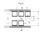
- FIG.2 shows an enlarged detailed cross section along with arrow II-II in FIG.1.
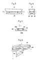
- FIG.3 shows a general layout illustration of EMT, shown in FIG.1, as ship propulsion systems.
- FIG.4 shows a front view of FIG.3.
- FIG.5 shows a cross section of a foil as shown in FIG.4.
- FIG.6 shows a vector schematic of the Lorentz's forces acting on the foil of FIG.4.
- FIG.7 shows a general layout illustration of EMTs mounted in the hull.
- FIG.8 shows a front view of FIG.7.
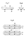
- FIG.9 shows a plane view of the arrangement of EMTs by computed by the present inventor.
- the thrust generator of the present invention provides a superconducting solenoid magnet 1 and a spiral thrust duct 2.
- the superconducting magnet 1 provides a coils 3 winded by superconducting wires to be a insulated in a highly efficient thermal container of cryostat
- the superconducting solenoid magnet generates strong magnetic field in the hollow interior 4 of the magnet (the direction of magnetic field as shown by arrow B).
- the superconducting solenoid magnet 3 is operating in the persistent current mode.
- the winding concept of superconducting solenoid magnet 3 may be a pancake type or a layered type.
- the thrust duct 2 is a spiral hollow one with rectangular cross section.
- the spiral portion of the thrust duct 2 is inserted in the hollow interior of the superconducting solenoid magnet 1.
- Both of an inlet 5 and an outlet 6, each having a opening 7, 8, of the thrust duct 2 extend along the longitudinal center axis 1a of the superconducting solenoid magnet 1. There is however no restriction concerning with cross section form of the thrust duct 2 in the present invention.
- Electrodes 9a,9b are fixed at both side walls of the thrust duct 2.
- the anode 9a is arranged on the inner side wall of the thrust duct 2
- the cathode 9b is opposed to the outer side wall of the thrust duct 2 because of decreasing effective electrochemical reaction area of the cathode 9b by producing hydrogen bubble.
- the present invention is not restricted concerning with arrangements of electrodes.
- the maximum thrust is obtained when the reaction between the outer radius ro and the inner radius ri of the thrust duct is, r o ⁇ 3.5 r i .
- TABLE 1 shows that the maximum Lorentz's force is able to be gained when the thrust duct dimension is satisfied with the relation, r o ⁇ 3.5 r i .
- FIG.3 to FIG. 6 shows a semi-submerged catamaran or an extended performance hydrofoil (EPH) in which the EMTs of the present invention are used for the propulsion system .
- EPH extended performance hydrofoil
- each EMT propulsion unit is mounted in a long, slender, submerged body.
- a fully-submerged foil 22 is mounted between two submerged bodies arranged by EMT propulsion units. Buoyant lift is combined with the dynamic lift of a fully-submerged foil 22 and the submerged body.
- This foil 22 has a superconducting racetrack magnet 23 in itself and a pair of electrodes 24 are fixed on the upper surface of the foil.
- FIG.6 shows the vector schematic of the forces acting upon the upper surface of the foil.
- the reaction between the magnetic field B by fixed the superconducting racetrack magnet in the foil and the electric current J from electrodes produces a Lorentz's force f, along the flow stream longitudinal axis of the foil 22.
- the sea water upon the surface of the foil is accelerated by Lorentz's force.
- the flow velocity difference between the upper surface 22a and the under surface generates lifting force L by Bernoulli's law.
- the lifting force per unit length L is calculated by the following equation.
- TABLE 2 shows the relation between flow velocity difference and lifting force.
- the basic principle of the hydrofoil concept is simply to lift a ship's hull out of the water and dynamically support it on wing-like lifting surfaces hydrofoils in order to reduce the power required to attain modestly high speeds.
- the lifting force generated by the water flow over the submerged portion of the foils increases causing the ship to rise and the submerged area of the foils to decrease.
- the ship will rise until the lifting force equals the weight carried by the foils.
- the lifting force is dependent on ship speed, hydrofoils in order to rise from water have to require large output propulsion units.
- lifting force is able to control by not only ship speed but also an electromagnetic force such that an electrode electric current, resulting in high thrust, reduction of hull weight and high ship speed.
- FIG.7 and FIG.8 show illustrations that two EMT propulsion units 20 are mounted in a row in the ship hull 21 to which a pair of EMT foils 25,25 is connected.
- the EMT foils system by the present invention is useful for the maneuver control of submarines.
- TABLE 3 shows the characteristics of Boeing 922 Jetfoil that is the only commercial hydrofoil in the world. The EMT foil is gained about two times propulsive efficiency as much as Boeing Jetfoil.
- the four rows of three pairs of superconducting EMT propulsion units 30 are arranged as shown in FIG.9.
- the superconducting shielding material devices 31 are mounted at both ends of two rows of EMT propulsion units, resulting in magnetic flux makes a close loop. As the results, the leakage of magnetic field is to be negligible and to increase the magnetic field.
- the superconducting shielding device is made by plates, thin films and coils of high Tc superconducting material or conventional superconducting material.
- the present invention is suitable for the ship propulsion system by generating thrust in the horizontal direction. And it is useful for a DP Systems to produce the thrust in the horizontal and vertical directions. It is possible to be used as large sea water pumps, flowing sea water into fixed EMTs and discharging from the duct. Using the reverse principle of EMTs, it is possible to use ocean currents (MHD) for power generators.
- MHD ocean currents
Landscapes
- Engineering & Computer Science (AREA)
- Power Engineering (AREA)
- Control Of Vehicles With Linear Motors And Vehicles That Are Magnetically Levitated (AREA)
- Reciprocating, Oscillating Or Vibrating Motors (AREA)
- Linear Motors (AREA)
- Vending Machines For Individual Products (AREA)
- Pyrane Compounds (AREA)
- Lubrication Of Internal Combustion Engines (AREA)
- Non-Mechanical Conveyors (AREA)
Applications Claiming Priority (1)
| Application Number | Priority Date | Filing Date | Title |
|---|---|---|---|
| PCT/JP1989/001153 WO1991007806A1 (fr) | 1989-11-10 | 1989-11-10 | Generateur de poussee |
Publications (3)
| Publication Number | Publication Date |
|---|---|
| EP0453567A1 true EP0453567A1 (de) | 1991-10-30 |
| EP0453567A4 EP0453567A4 (en) | 1992-04-01 |
| EP0453567B1 EP0453567B1 (de) | 1994-05-04 |
Family
ID=13958933
Family Applications (1)
| Application Number | Title | Priority Date | Filing Date |
|---|---|---|---|
| EP89912497A Expired - Lifetime EP0453567B1 (de) | 1989-11-10 | 1989-11-10 | Schuberzeuger |
Country Status (5)
| Country | Link |
|---|---|
| US (1) | US5314311A (de) |
| EP (1) | EP0453567B1 (de) |
| AT (1) | ATE105447T1 (de) |
| DE (1) | DE68915177D1 (de) |
| WO (1) | WO1991007806A1 (de) |
Cited By (2)
| Publication number | Priority date | Publication date | Assignee | Title |
|---|---|---|---|---|
| WO2011068633A3 (en) * | 2009-12-02 | 2011-09-22 | Vetco Gray Inc. | Pumping mud by electrohydrodynamic propulsion |
| WO2012064379A1 (en) * | 2010-11-09 | 2012-05-18 | Vetco Gray Inc. | Pumping mud by electrohydrodynamic propulsion |
Families Citing this family (8)
| Publication number | Priority date | Publication date | Assignee | Title |
|---|---|---|---|---|
| JP3045754B2 (ja) * | 1990-09-21 | 2000-05-29 | 栄一 多田 | 推力発生装置 |
| EP0931931A1 (de) * | 1998-01-27 | 1999-07-28 | Entry-Technology | Magnetohydrodynamisches (MHD) Umwandlungssystem von Meeresströmungen |
| FR2794039B1 (fr) * | 1999-05-27 | 2002-05-03 | Osmooze Sa | Dispositif de formation, de deplacement et de diffusion de petites quantites calibrees de liquides |
| RU2226737C2 (ru) * | 2002-03-29 | 2004-04-10 | Красноярский государственный технический университет | Магнитогидродинамический способ преобразования тепловой энергии в электрическую замкнутого цикла |
| EP1437822A1 (de) * | 2003-01-13 | 2004-07-14 | Siemens Aktiengesellschaft | Strömungsmaschine und Verfahren zum Betrieb einer Strömungsmaschine |
| DE102004044539B4 (de) * | 2004-09-10 | 2008-08-28 | Technische Universität Dresden | Einrichtung zum Bewegen von elektrisch leitenden flüssigen Medien |
| AU2007202160B1 (en) * | 2007-05-14 | 2008-01-10 | Kristos Mavros | Ether Propeller |
| KR102682310B1 (ko) * | 2022-01-04 | 2024-07-04 | 김병진 | 변형가변나선 실린더 및 이를 이용한 프로펠러와 노즐 |
Family Cites Families (18)
| Publication number | Priority date | Publication date | Assignee | Title |
|---|---|---|---|---|
| GB889950A (en) * | 1957-06-19 | 1962-02-21 | Gen Electric | Faraday electromagnetic pump |
| US2997013A (en) * | 1958-07-18 | 1961-08-22 | Carl E Grebe | Propulsion system |
| US3372644A (en) * | 1966-03-21 | 1968-03-12 | Gen Electric | Electromagnetic pump having concentric electrodes |
| GB1238803A (de) * | 1969-05-28 | 1971-07-14 | ||
| FR2112791A5 (en) * | 1970-11-09 | 1972-06-23 | Alsthom | Electromagnetic pump - needs no moving part to convey liquid which conducts electricity |
| GB1556258A (en) * | 1977-03-23 | 1979-11-21 | Atomic Energy Authority Uk | Electromagnetic pumps |
| GB1563170A (en) * | 1977-08-18 | 1980-03-19 | Nauch Proizv Obiedine | Linear a c generator |
| JPS5519636A (en) * | 1978-07-25 | 1980-02-12 | Kawasaki Heavy Ind Ltd | Electromagnetic propulsion device for shipping |
| US4527955A (en) * | 1982-01-08 | 1985-07-09 | United Kingdom Atomic Energy Authority | Electromagnetic pumps of the helical linear induction type |
| JPH0684159B2 (ja) * | 1985-09-18 | 1994-10-26 | 株式会社前川製作所 | 海水船舶用推進装置 |
| JPS63129280A (ja) * | 1986-11-18 | 1988-06-01 | 株式会社東芝 | ヘリウム冷却装置 |
| US4767364A (en) * | 1987-01-14 | 1988-08-30 | Erwin Lenz | Advanced steering and propulsion system for ships |
| US4782671A (en) * | 1987-09-28 | 1988-11-08 | General Atomics | Cooling apparatus for MRI magnet system and method of use |
| EP0428652B1 (de) * | 1989-05-24 | 1997-08-06 | LAUKIEN, Günther, Prof. Dr. | Verfahren und vorrichtung zum antreiben von wasserfahrzeugen |
| DE3916882A1 (de) * | 1989-05-24 | 1990-11-29 | Laukien Guenther | Verfahren und vorrichtung zum antreiben von wasserfahrzeugen |
| JPH03248995A (ja) * | 1990-02-27 | 1991-11-06 | Mitsubishi Heavy Ind Ltd | 船舶の推進システム |
| US5087215A (en) * | 1990-03-08 | 1992-02-11 | Leonid Simuni | Ocean-going vessel and method for increasing the speed |
| US5117141A (en) * | 1990-07-30 | 1992-05-26 | The United States Of America As Represented By Department Of Energy | Disc rotors with permanent magnets for brushless DC motor |
-
1989
- 1989-11-10 DE DE68915177T patent/DE68915177D1/de not_active Expired - Lifetime
- 1989-11-10 AT AT8989912497T patent/ATE105447T1/de not_active IP Right Cessation
- 1989-11-10 EP EP89912497A patent/EP0453567B1/de not_active Expired - Lifetime
- 1989-11-10 US US07/752,552 patent/US5314311A/en not_active Expired - Fee Related
- 1989-11-10 WO PCT/JP1989/001153 patent/WO1991007806A1/ja not_active Ceased
Cited By (8)
| Publication number | Priority date | Publication date | Assignee | Title |
|---|---|---|---|---|
| WO2011068633A3 (en) * | 2009-12-02 | 2011-09-22 | Vetco Gray Inc. | Pumping mud by electrohydrodynamic propulsion |
| GB2488702A (en) * | 2009-12-02 | 2012-09-05 | Vetco Gray Inc | Pumping mud by electrohydrodynamic propulsion |
| US8632318B2 (en) | 2009-12-02 | 2014-01-21 | Vetco Gray Inc. | Pumping mud by electrohydrodynamic propulsion |
| US8684701B2 (en) | 2009-12-02 | 2014-04-01 | Vetco Gray Inc. | Pumping mud by electrohydrodynamic propulsion |
| GB2488702B (en) * | 2009-12-02 | 2015-10-21 | Vetco Gray Inc | Pumping mud by electrohydrodynamic propulsion |
| WO2012064379A1 (en) * | 2010-11-09 | 2012-05-18 | Vetco Gray Inc. | Pumping mud by electrohydrodynamic propulsion |
| GB2502199A (en) * | 2010-11-09 | 2013-11-20 | Vetco Gray Inc | Pumping mud by electrohydrodynamic propulsion |
| GB2502199B (en) * | 2010-11-09 | 2018-10-03 | Vetco Gray Inc | Pumping mud by electrohydrodynamic propulsion |
Also Published As
| Publication number | Publication date |
|---|---|
| DE68915177D1 (de) | 1994-06-09 |
| EP0453567A4 (en) | 1992-04-01 |
| WO1991007806A1 (fr) | 1991-05-30 |
| US5314311A (en) | 1994-05-24 |
| EP0453567B1 (de) | 1994-05-04 |
| ATE105447T1 (de) | 1994-05-15 |
Similar Documents
| Publication | Publication Date | Title |
|---|---|---|
| EP0500970B1 (de) | Schuberzeuger | |
| EP0453567A1 (de) | Schuberzeuger | |
| Way | Electromagnetic propulsion for cargo submarines | |
| US2997013A (en) | Propulsion system | |
| US5240569A (en) | Magnetically enhanced electrolysis cell system | |
| US5249990A (en) | Method and apparatus for the propulsion of water vehicles | |
| JP2523407B2 (ja) | 船舶を駆動する方法及び装置 | |
| US3106058A (en) | Propulsion system | |
| CN114992052A (zh) | 一种具有新能源发电功能的三体船 | |
| US6059236A (en) | Tangential force panel for active flow control of a conductive fluid | |
| JP2736469B2 (ja) | 推力発生装置 | |
| JPS5519636A (en) | Electromagnetic propulsion device for shipping | |
| WO1989009724A1 (en) | Magnetohydrodynamic propulsion arrangements | |
| JPWO1991007806A1 (ja) | 推力発生装置 | |
| JPH0684159B2 (ja) | 海水船舶用推進装置 | |
| CN214336080U (zh) | 一种电磁推进船模 | |
| JP2002127988A (ja) | 海流発電潜水船 | |
| Way et al. | Prospects for the electromagnetic submarine | |
| Rodrigues | Magnetohydrodynamic Propulsion for Electric Ships | |
| Way | Research Submarines with Minimal Ocean Disturbance | |
| US5087215A (en) | Ocean-going vessel and method for increasing the speed | |
| Roy | Electromagnetic marine propulsion: recent advances and future challenges | |
| JPH03235796A (ja) | 超電導電磁推進船用推進装置 | |
| Constontine et al. | THEORETICAL AND EXPERIMENTAL STUDY OF SMALL SCALE MAGNETO-HYDRODYNAMIC (MHD) SHIP PROPULSION | |
| Boissonneau et al. | Aspects of MHD in sea water |
Legal Events
| Date | Code | Title | Description |
|---|---|---|---|
| PUAI | Public reference made under article 153(3) epc to a published international application that has entered the european phase |
Free format text: ORIGINAL CODE: 0009012 |
|
| AK | Designated contracting states |
Kind code of ref document: A1 Designated state(s): AT BE CH DE FR GB IT LI LU NL SE |
|
| 17P | Request for examination filed |
Effective date: 19911125 |
|
| A4 | Supplementary search report drawn up and despatched |
Effective date: 19920207 |
|
| AK | Designated contracting states |
Kind code of ref document: A4 Designated state(s): AT BE CH DE FR GB IT LI LU NL SE |
|
| 17Q | First examination report despatched |
Effective date: 19921207 |
|
| GRAA | (expected) grant |
Free format text: ORIGINAL CODE: 0009210 |
|
| AK | Designated contracting states |
Kind code of ref document: B1 Designated state(s): AT BE CH DE FR GB IT LI LU NL SE |
|
| PG25 | Lapsed in a contracting state [announced via postgrant information from national office to epo] |
Ref country code: IT Free format text: LAPSE BECAUSE OF FAILURE TO SUBMIT A TRANSLATION OF THE DESCRIPTION OR TO PAY THE FEE WITHIN THE PRE;WARNING: LAPSES OF ITALIAN PATENTS WITH EFFECTIVE DATE BEFORE 2007 MAY HAVE OCCURRED AT ANY TIME BEFORE 2007. THE CORRECT EFFECTIVE DATE MAY BE DIFFERENT FROM THE ONE RECORDED.SCRIBED TIME-LIMIT Effective date: 19940504 Ref country code: BE Effective date: 19940504 Ref country code: CH Effective date: 19940504 Ref country code: DE Effective date: 19940504 Ref country code: NL Effective date: 19940504 Ref country code: LI Effective date: 19940504 Ref country code: AT Effective date: 19940504 |
|
| REF | Corresponds to: |
Ref document number: 105447 Country of ref document: AT Date of ref document: 19940515 Kind code of ref document: T |
|
| REF | Corresponds to: |
Ref document number: 68915177 Country of ref document: DE Date of ref document: 19940609 |
|
| K2C2 | Correction of patent specification (partial reprint) published |
Effective date: 19940504 |
|
| REG | Reference to a national code |
Ref country code: CH Ref legal event code: PL |
|
| ET | Fr: translation filed | ||
| NLV1 | Nl: lapsed or annulled due to failure to fulfill the requirements of art. 29p and 29m of the patents act | ||
| PG25 | Lapsed in a contracting state [announced via postgrant information from national office to epo] |
Ref country code: LU Free format text: LAPSE BECAUSE OF NON-PAYMENT OF DUE FEES Effective date: 19941130 |
|
| EAL | Se: european patent in force in sweden |
Ref document number: 89912497.8 |
|
| PLBE | No opposition filed within time limit |
Free format text: ORIGINAL CODE: 0009261 |
|
| STAA | Information on the status of an ep patent application or granted ep patent |
Free format text: STATUS: NO OPPOSITION FILED WITHIN TIME LIMIT |
|
| 26N | No opposition filed | ||
| REG | Reference to a national code |
Ref country code: GB Ref legal event code: IF02 |
|
| PGFP | Annual fee paid to national office [announced via postgrant information from national office to epo] |
Ref country code: GB Payment date: 20031027 Year of fee payment: 15 |
|
| PGFP | Annual fee paid to national office [announced via postgrant information from national office to epo] |
Ref country code: FR Payment date: 20031120 Year of fee payment: 15 |
|
| PGFP | Annual fee paid to national office [announced via postgrant information from national office to epo] |
Ref country code: SE Payment date: 20031124 Year of fee payment: 15 |
|
| PG25 | Lapsed in a contracting state [announced via postgrant information from national office to epo] |
Ref country code: GB Free format text: LAPSE BECAUSE OF NON-PAYMENT OF DUE FEES Effective date: 20041110 |
|
| PG25 | Lapsed in a contracting state [announced via postgrant information from national office to epo] |
Ref country code: SE Free format text: LAPSE BECAUSE OF NON-PAYMENT OF DUE FEES Effective date: 20041111 |
|
| GBPC | Gb: european patent ceased through non-payment of renewal fee |
Effective date: 20041110 |
|
| EUG | Se: european patent has lapsed | ||
| PG25 | Lapsed in a contracting state [announced via postgrant information from national office to epo] |
Ref country code: FR Free format text: LAPSE BECAUSE OF NON-PAYMENT OF DUE FEES Effective date: 20050729 |
|
| REG | Reference to a national code |
Ref country code: FR Ref legal event code: ST |