EP0453589B1 - Dispositif de stimulation des tissus - Google Patents
Dispositif de stimulation des tissus Download PDFInfo
- Publication number
- EP0453589B1 EP0453589B1 EP90107693A EP90107693A EP0453589B1 EP 0453589 B1 EP0453589 B1 EP 0453589B1 EP 90107693 A EP90107693 A EP 90107693A EP 90107693 A EP90107693 A EP 90107693A EP 0453589 B1 EP0453589 B1 EP 0453589B1
- Authority
- EP
- European Patent Office
- Prior art keywords
- stimulation
- sensitivity
- tissue
- determination
- pulses
- Prior art date
- Legal status (The legal status is an assumption and is not a legal conclusion. Google has not performed a legal analysis and makes no representation as to the accuracy of the status listed.)
- Expired - Lifetime
Links
- 230000004936 stimulating effect Effects 0.000 title 1
- 230000000638 stimulation Effects 0.000 claims description 191
- 230000035945 sensitivity Effects 0.000 claims description 60
- 230000002051 biphasic effect Effects 0.000 claims description 18
- 238000000034 method Methods 0.000 claims description 9
- 230000000737 periodic effect Effects 0.000 claims description 2
- 230000007423 decrease Effects 0.000 claims 1
- 210000001519 tissue Anatomy 0.000 description 39
- 239000003990 capacitor Substances 0.000 description 12
- 230000008569 process Effects 0.000 description 6
- 238000010586 diagram Methods 0.000 description 5
- 230000008859 change Effects 0.000 description 4
- 230000010287 polarization Effects 0.000 description 4
- 230000000747 cardiac effect Effects 0.000 description 3
- 238000001514 detection method Methods 0.000 description 3
- 230000000694 effects Effects 0.000 description 2
- 238000005265 energy consumption Methods 0.000 description 2
- 230000004044 response Effects 0.000 description 2
- 230000036982 action potential Effects 0.000 description 1
- 230000008901 benefit Effects 0.000 description 1
- 230000008602 contraction Effects 0.000 description 1
- 230000003247 decreasing effect Effects 0.000 description 1
- 210000005003 heart tissue Anatomy 0.000 description 1
- 238000011835 investigation Methods 0.000 description 1
- 230000002123 temporal effect Effects 0.000 description 1
Images
Classifications
-
- A—HUMAN NECESSITIES
- A61—MEDICAL OR VETERINARY SCIENCE; HYGIENE
- A61N—ELECTROTHERAPY; MAGNETOTHERAPY; RADIATION THERAPY; ULTRASOUND THERAPY
- A61N1/00—Electrotherapy; Circuits therefor
- A61N1/18—Applying electric currents by contact electrodes
- A61N1/32—Applying electric currents by contact electrodes alternating or intermittent currents
- A61N1/36—Applying electric currents by contact electrodes alternating or intermittent currents for stimulation
- A61N1/362—Heart stimulators
- A61N1/37—Monitoring; Protecting
- A61N1/3706—Pacemaker parameters
-
- A—HUMAN NECESSITIES
- A61—MEDICAL OR VETERINARY SCIENCE; HYGIENE
- A61N—ELECTROTHERAPY; MAGNETOTHERAPY; RADIATION THERAPY; ULTRASOUND THERAPY
- A61N1/00—Electrotherapy; Circuits therefor
- A61N1/18—Applying electric currents by contact electrodes
- A61N1/32—Applying electric currents by contact electrodes alternating or intermittent currents
- A61N1/36—Applying electric currents by contact electrodes alternating or intermittent currents for stimulation
- A61N1/362—Heart stimulators
- A61N1/365—Heart stimulators controlled by a physiological parameter, e.g. heart potential
Definitions
- the invention relates to an arrangement for tissue stimulation in a living being with a stimulation pulse generator for generating stimulation pulses, with a detector device for detecting the reaction of the tissue to the stimulation and with a control device which controls the stimulation generator and which reduces the energy of the tissue to determine the stimulation sensitivity of the tissue Stimulation impulses starting from a value above the stimulation sensitivity until there is no reaction of the tissue.
- Such an arrangement is a pacemaker with which the heart of a patient is stimulated with the aid of stimulation pulses.
- a contraction occurs as a reaction of the heart only when the energy of the stimulation impulses exceeds a certain stimulation sensitivity or stimulation threshold of the heart tissue, which varies from patient to patient.
- the energy of successive stimulation pulses is gradually reduced and the reaction or response of the heart to the stimulation is monitored. If there is no such reaction, the stimulation energy is increased to a value which is certainly above the stimulation sensitivity of the heart and the same process is repeated. This adjusts the stimulation energy and thus the energy consumption within the pacemaker to the changeable stimulation sensitivity of the heart.
- the stimulation energy is reduced by a certain value each time when a cardiac reaction has also been detected in the two immediately preceding stimulation events. If, on the other hand, no cardiac reaction to the current stimulation is registered, the heart is stimulated with a stimulation pulse with maximum energy and for the next stimulation pulse an energy content increased by a certain value compared to the unsuccessful stimulation pulse.
- the stimulation energy is adjusted either at fixed time intervals or on the command of an external programmer.
- the invention has for its object to provide an arrangement for tissue stimulation, in which on the one hand the emitted stimulation energy is adapted to the changing course of the stimulation sensitivity of the tissue, but on the other hand the patient is not constantly burdened by a lack of stimulation as a result of the stimulation sensitivity falling below.
- the object is achieved in that, in the arrangement of the type specified at the outset, the control device carries out the determination of the stimulation sensitivity at periodic time intervals and in that the time interval between a current determination of the stimulation sensitivity and the next determination depends on the difference between the currently determined Value of the stimulation sensitivity and the previously determined value of the stimulation sensitivity is measured, the time interval being reduced with increasing difference and increasing with decreasing difference.
- the main advantage of the arrangement according to the invention is that the determination of the stimulation sensitivity not constantly, but at certain time intervals, the length of which varies depending on the change in the stimulation sensitivity, so that if there are only slight changes in the stimulation sensitivity, this is determined anew in larger time intervals with a correspondingly low load on the patient, while for larger changes in the stimulation sensitivity the time interval between successive determinations of the stimulation sensitivity is reduced in order to be able to follow their changes. In this way, the burden on the patient due to unsuccessful stimulation attempts, such as occur in each individual investigation process, is significantly reduced.
- the difference between the current and the previously determined value of the stimulation sensitivity, which is used to measure the time interval, is preferably standardized in the control device to the time interval between these two determination processes.
- the time interval between successive determinations of the stimulation sensitivity is adapted to the change in the stimulation sensitivity of the tissue to be stimulated per unit of time, that is to say to the rate of change.
- the invention provides that the stimulation pulse generator emits stimulation pulses after each determination of the stimulation sensitivity until its next determination, the energy of which corresponds to the currently determined value of the stimulation sensitivity plus a safety value .
- this safety value is dimensioned such that in the case of a If the stimulation sensitivity increases during this period, the energy of the stimulation pulses generated is always above the stimulation sensitivity of the tissue.
- the stimulation pulse generator generates biphasic stimulation pulses for determining the stimulation sensitivity and then monophasic stimulation pulses until the next determination of the stimulation sensitivity.
- biphasic stimulation pulses e.g. from DE-OS 23 42 030 or from DE-OS 26 19 001 are known, namely that the polarization phenomena generated by the stimulation pulse in the tissue disappear so quickly that a reliable detection of the reaction of the tissue to the stimulation is possible .
- the energy requirement of such biphasic pulses is relatively large compared to monophasic pulses.
- the arrangement according to the invention does not generate the biphasic stimulation pulses continuously, but rather only at certain time intervals to determine the sensitivity of the tissue to stimulation, while the tissue is excited in the meantime with monophasic stimulation pulses, the total energy requirement for the stimulation is only low.
- the biphasic stimulation pulses preferably each have two energy pulses of different polarity with a pause lying between them.
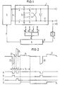
- the pacemaker contains a stimulation pulse generator (1) to which an indifferent electrode (2) and a stimulation electrode (3) are connected on the output side.
- the indifferent electrode (2) is formed by the housing of the pacemaker, not shown here, while the stimulation electrode (3) is placed in the heart.
- the stimulation pulse generator (1) is connected on the input side to the output (4) of a stimulation voltage generator (5) which supplies the stimulation pulse generator (1) with a predefinable voltage for the stimulation pulses to be generated.
- the respective value for this voltage is specified by a control device (6) which is connected to the stimulation voltage generator (5) via a control line (7).
- the control device (6) is also connected to a timer device (9) via a further control line (8) on the output side. connected, which, as will be explained below, controls the time course of the generation of the stimulation pulses in the stimulation pulse generator (1).
- the stimulation electrode (3) is connected to a detector device (10) which detects the reaction of the stimulated tissue after a stimulation pulse; at its output (11) the detector device (10) is connected to a control input (12) of the control device (6).
- the detector device (10) can also be connected to a measuring electrode (13) arranged in the vicinity thereof, as shown in dashed lines in FIG.
- a storage capacitor (14) is connected at its connections (15, 16) via a first pair of switches A to the output (4) of the stimulation voltage generator (5).
- the storage capacitor (14) is also connected to the indifferent electrode (2) via a second switch pair B and a third switch pair C, which are arranged in a bridge circuit, and to the stimulation electrode (3) via an output capacitor (17).
- the storage capacitor (14) is connected at its connection (15) to the indifferent electrode (2) and at its connection (16) to the output capacitor (17) or vice versa with its connection (16) to the indifferent electrode (2) and with the connection (15) to the output capacitor (17).
- a switch D is provided which connects the stimulation electrode (3) to the indifferent electrode (2) via the output capacitor (17).
- the switch pairs A, B and C and the switch D are via the control lines (18, 19, 20, 21) assigned to them by the timer device (9) individually controlled, as will be explained below with reference to FIG 2.
- FIG. 2 shows in a time diagram an example of a biphasic stimulation pulse (22), which consists of a negative partial pulse (23) followed by a positive partial pulse (24) and a quick discharge pulse (25); Furthermore, a monophasic stimulation pulse (26) and the control signals emitted by the timer device (9) to the switch pairs A, B and C and the switch D for generating the stimulation pulses (22, 26) can be seen.
- a signal state deviating from zero means that the assigned switch is closed.
- the storage capacitor (14) is charged to the output voltage specified by the control device (6) and generated by the stimulation voltage generator (5).
- the switch pair B is first closed for a period of time t 1 and after a subsequent break t 2, the switch pair C for a period of time t 3; finally, after another pause t4 the switch D is closed for a period of time t5, as a result of which the output capacitor (17) is quickly discharged.
- the polarization phenomena generated in the tissue due to the stimulation in the region of the stimulation electrode (3) are broken down so quickly that a reliable detection of the reaction of the tissue to the biphasic stimulation is largely free of interference from the polarization phenomena is possible by means of the detector device (10).
- the monophasic stimulation pulse (26) which is easier to generate, can be used for tissue stimulation instead of the biphasic stimulation pulse (22); This is because the action potential in the tissue arrives with a time delay from the stimulation electrode (2) to the measuring electrode (13), so that the polarization phenomena have largely subsided during this time.
- the monophasic stimulation pulse designated by (26) is generated by closing the switch pair B.
- the output capacitor (17) is then discharged by closing the switch D with a quick discharge pulse (27).
- the energy content of the monophasic stimulation pulse (26) with the same amplitude is approximately half that of the biphasic stimulation pulse (22).
- Both stimulation pulses (22, 26) have approximately the same effect in spite of their different energy content during tissue stimulation. This is because the stimulation sensitivity of the tissue depends not only on the actual energy content of the respective stimulation pulse, but also on its shape. If, therefore, stimulation energy in relation to the stimulation sensitivity of the tissue is mentioned below, then two different stimulation impulses are to be regarded as having the same energy if they have the same effect in tissue stimulation.
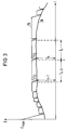
- FIG. 3 shows (28) a possible course of the stimulation sensitivity of the tissue to be stimulated as a function of the time t.
- the stimulation sensitivity is expressed by an energy value E which a stimulation pulse must have at least for successful stimulation of the tissue.
- E max a maximum energy
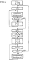
- the stimulation energy is adapted to the variable stimulation sensitivity of the tissue in accordance with the course of the curve denoted by (29) and the method steps shown in FIG. 4 in the form of a flow diagram.
- the stimulation sensitivity of the tissue is determined at a point in time designated by n in FIG. 3.
- a value S n-1 was last determined for the stimulation sensitivity before a time interval T n-1 ; the tissue was then excited up to the point in time n with a stimulation energy lying above the determined stimulation sensitivity S n-1 by a safety value E0 (curve 29).
- a timer T (FIG. 4) is reset to the value zero.
- the stimulation energy E is reduced by one energy level, the timer T is incremented and a new biphasic stimulation pulse (22) is generated this time with the reduced stimulation energy E after a stimulation time interval (not shown here). This process is repeated until there is no response from the tissue because the current stimulation sensitivity S n has been undershot.
- the energy change in the biphasic stimulation pulse (22) can take place by varying the pulse duration and / or pulse amplitude.
- the stimulation sensitivity S n-1 determined last before, based on the time interval T n-1 between the two determination processes for the stimulation sensitivity, is determined a new time interval T n from the beginning of the current determination to the next determination of the stimulation sensitivity. Subsequently, the tissue with the monophasic stimulation pulses (26) (FIG. 2) and a stimulation energy lying around the safety value E0 above the determined stimulation sensitivity S n E S n + E0 excited until the timer T incremented after each new stimulation indicates the expiration of the time period T n . The stimulation sensitivity of the tissue is then determined again as described above.
- a biphasic stimulation pulse (22) can be generated periodically, for example after every tenth stimulation pulse, and the detector device (10) can be used to check whether the stimulation energy is still sufficient for tissue stimulation. If this is not the case, the stimulation energy is increased. If the detector device (10) is connected to the measuring electrode (13), the monophasic stimulation can be checked for sufficient stimulation energy continuously after each stimulation pulse (26).
- the stimulation energy (29) is adapted to the course of the stimulation sensitivity (28), but the burden on the patient due to a lack of stimulation is as low as possible.
Landscapes
- Health & Medical Sciences (AREA)
- Heart & Thoracic Surgery (AREA)
- Life Sciences & Earth Sciences (AREA)
- Cardiology (AREA)
- Engineering & Computer Science (AREA)
- Biophysics (AREA)
- Biomedical Technology (AREA)
- Nuclear Medicine, Radiotherapy & Molecular Imaging (AREA)
- Radiology & Medical Imaging (AREA)
- Animal Behavior & Ethology (AREA)
- General Health & Medical Sciences (AREA)
- Public Health (AREA)
- Veterinary Medicine (AREA)
- Physiology (AREA)
- Electrotherapy Devices (AREA)
Claims (5)
- Dispositif pour stimuler des tissus chez un être vivant, comportant un générateur d'impulsions de stimulation (1) servant à produire des impulsions de stimulation (22,26), un dispositif de détection (10) pour détecter la réaction du tissu à la stimulation et un dispositif de commande (6), qui commande le générateur d'impulsions de stimulation (1) et qui, pour la détermination de la sensibilité du tissu à la stimulation, déclenche une réduction de l'énergie des impulsions de stimulation (22,26) à partir d'une valeur supérieure à la sensibilité à la stimulation, jusqu'à ce que le tissu ne réagisse plus, caractérisé par le fait que le dispositif de commande (6) exécute la détermination de la sensibilité à la stimulation pendant des intervalles de temps périodiques Tn-1, Tn, et que l'intervalle de temps Tn entre une détermination actuelle de la sensibilité à la stimulation Sn et la détermination suivante est mesuré en fonction de la différence entre la valeur actuelle déterminée de la sensibilité à la stimulation Sn et la valeur déterminée auparavant de la sensibilité à la stimulation Sn-1, l'intervalle de temps Tn étant réduit lorsque la différence augmente et étant accru lorsque la différence diminue.
- Dispositif suivant la revendication 1, caractérisé par le fait que dans le dispositif de commande (6), la différence, utilisée pour le dimensionnement de l'intervalle de temps Tn, entre la valeur actuelle déterminée et la valeur déterminée auparavant de la sensibilité à la stimulation, à savoir Sn et Sn-1, est normalisée en étant rapportée à l'intervalle de temps Tn-1 entre ces deux processus de détermination.
- Dispositif suivant la revendication 1 ou 2, caractérisé par le fait qu'après chaque détermination de la sensibilité à la stimulation Sn, le générateur d'impulsions de stimulation (1) délivre, jusqu'à la détermination immédiatement suivante de cette sensibilité, des impulsions de stimulation (26), dont l'énergie correspond à la valeur, actuelle déterminée, de la sensibilité à la stimulation Sn, plus une valeur de sécurité E₀.
- Dispositif suivant l'une des revendications précédentes, caractérisé par le fait que le générateur d'impulsions de stimulation (1) produit, pour la détermination de la sensibilité à la stimulation, des impulsions de stimulation biphasées (22) et ensuite, jusqu'à la détermination suivante de la sensibilité à la stimulation, délivre des impulsions de stimulation monophasées (26).
- Dispositif suivant la revendication 4, caractérisé par le fait que les impulsions de stimulation biphasées (22) comprennent respectivement deux impulsions partielles (23,24) possédant une même énergie et des polarités différentes, avec une pause t₂ intercalée entre ces impulsions partielles.
Priority Applications (4)
| Application Number | Priority Date | Filing Date | Title |
|---|---|---|---|
| EP90107693A EP0453589B1 (fr) | 1990-04-24 | 1990-04-24 | Dispositif de stimulation des tissus |
| DE59008148T DE59008148D1 (de) | 1990-04-24 | 1990-04-24 | Anordnung zur Gewebestimulation. |
| US07/685,128 US5165404A (en) | 1990-04-24 | 1991-04-12 | Biological tissue stimulation device with control means for determining stimulation sensitivity calculation timing |
| JP3119179A JPH04227277A (ja) | 1990-04-24 | 1991-04-22 | 組織刺激装置 |
Applications Claiming Priority (1)
| Application Number | Priority Date | Filing Date | Title |
|---|---|---|---|
| EP90107693A EP0453589B1 (fr) | 1990-04-24 | 1990-04-24 | Dispositif de stimulation des tissus |
Publications (2)
| Publication Number | Publication Date |
|---|---|
| EP0453589A1 EP0453589A1 (fr) | 1991-10-30 |
| EP0453589B1 true EP0453589B1 (fr) | 1994-12-28 |
Family
ID=8203901
Family Applications (1)
| Application Number | Title | Priority Date | Filing Date |
|---|---|---|---|
| EP90107693A Expired - Lifetime EP0453589B1 (fr) | 1990-04-24 | 1990-04-24 | Dispositif de stimulation des tissus |
Country Status (4)
| Country | Link |
|---|---|
| US (1) | US5165404A (fr) |
| EP (1) | EP0453589B1 (fr) |
| JP (1) | JPH04227277A (fr) |
| DE (1) | DE59008148D1 (fr) |
Families Citing this family (21)
| Publication number | Priority date | Publication date | Assignee | Title |
|---|---|---|---|---|
| IT1240362B (it) * | 1990-03-30 | 1993-12-10 | Medisan S.L.R. | Procedimento per l'elettrostimolazione di una massa muscolare al fine di migliorarne l'aspetto estetico, ed apparecchio per l'attuazione del procedimento |
| DE4013048B4 (de) * | 1990-04-24 | 2004-07-08 | St. Jude Medical Ab | Anordnung zur Gewebestimulation |
| US5320643A (en) * | 1992-10-06 | 1994-06-14 | Medtronic, Inc. | Automatic cardiac capture restoration and threshold-seeking method and apparatus |
| US5601615A (en) * | 1994-08-16 | 1997-02-11 | Medtronic, Inc. | Atrial and ventricular capture detection and threshold-seeking pacemaker |
| US7027868B2 (en) | 2001-10-30 | 2006-04-11 | Medtronic, Inc. | Capture management improvements |
| US7280868B2 (en) * | 1994-08-16 | 2007-10-09 | Medtronic, Inc. | Capture management improvements |
| EP0867102A4 (fr) * | 1995-12-01 | 2000-10-04 | Cochlear Ltd | Dispositif a retroaction servant a reguler les tensions d'electrodes dans un stimulateur cochleaire et appareil analogue |
| SE9600310D0 (sv) | 1996-01-29 | 1996-01-29 | Pacesetter Ab | Hjärtstimulator |
| US5772693A (en) * | 1996-02-09 | 1998-06-30 | Cardiac Control Systems, Inc. | Single preformed catheter configuration for a dual-chamber pacemaker system |
| US5683431A (en) * | 1996-03-27 | 1997-11-04 | Medtronic, Inc. | Verification of capture by sensing evoked response across cardioversion electrodes |
| US5702427A (en) * | 1996-03-28 | 1997-12-30 | Medtronic, Inc. | Verification of capture using pressure waves transmitted through a pacing lead |
| US6148234A (en) | 1998-09-28 | 2000-11-14 | Medtronic Inc. | Dual site pacing system with automatic pulse output adjustment |
| US7130690B2 (en) * | 2003-07-23 | 2006-10-31 | Medtronic, Inc. | Atrial capture management during atrial and ventricular pacing |
| GB0709834D0 (en) * | 2007-05-22 | 2007-07-04 | Gillbe Ivor S | Array stimulator |
| US10512424B2 (en) | 2013-12-23 | 2019-12-24 | Medtronic, Inc. | Method and apparatus for selecting activity response vector |
| US9814887B2 (en) | 2014-02-06 | 2017-11-14 | Medtronic, Inc. | Selection of optimal accelerometer sensing axis for rate response in leadless pacemaker |
| US9308376B2 (en) | 2014-02-24 | 2016-04-12 | Medtronic, Inc. | Method and apparatus for detecting loss of capture |
| US9452292B2 (en) | 2014-02-24 | 2016-09-27 | Medtronic, Inc. | Method and apparatus for detecting loss of capture |
| US9724518B2 (en) | 2014-11-25 | 2017-08-08 | Medtronic, Inc. | Dynamic patient-specific filtering of an activity signal within a beating heart |
| US9937352B2 (en) | 2015-10-22 | 2018-04-10 | Medtronic, Inc. | Rate responsive cardiac pacing control using posture |
| CN115282474B (zh) * | 2022-05-18 | 2026-02-03 | 未来穿戴健康科技股份有限公司 | 一种电刺激按摩装置及其控制方法和存储介质 |
Family Cites Families (14)
| Publication number | Priority date | Publication date | Assignee | Title |
|---|---|---|---|---|
| BE791120A (fr) * | 1971-11-11 | 1973-03-01 | Medtronic Inc | |
| DE2342030A1 (de) * | 1973-08-20 | 1975-03-27 | Siemens Ag | Elektrischer herzschrittmacher |
| DE2619001C2 (de) * | 1976-04-29 | 1985-10-31 | Siemens AG, 1000 Berlin und 8000 München | Herzschrittmacher |
| US4402322A (en) * | 1981-03-25 | 1983-09-06 | Medtronic, Inc. | Pacer output circuit |
| US4729376A (en) * | 1985-05-28 | 1988-03-08 | Cordis Corporation | Cardiac pacer and method providing means for periodically determining capture threshold and adjusting pulse output level accordingly |
| EP0236562B2 (fr) * | 1985-12-11 | 2006-06-07 | Telectronics N.V. | Appareil pour stimulation cardiaque avec détection des potentiels cardiaques provoqués |
| US4969467A (en) * | 1988-03-25 | 1990-11-13 | Telectronics N.V. | Pacemaker with improved automatic output regulation |
| US4969462A (en) * | 1988-03-25 | 1990-11-13 | Telectronics N.V. | Pacemaker with improved automatic output regulation |
| US4878497A (en) * | 1988-03-25 | 1989-11-07 | Telectronics N.V. | Pacemaker with improved automatic output regulation |
| US4969460A (en) * | 1988-03-25 | 1990-11-13 | Telectronics N.V. | Pacemaker with improved automatic output regulation |
| US4955376A (en) * | 1988-03-25 | 1990-09-11 | Teletronics N.V. | Pacemaker with improved automatic output regulation |
| US4969464A (en) * | 1988-03-25 | 1990-11-13 | Telectronics N.V. | Pacemaker with improved automatic output regulation |
| US4969461A (en) * | 1988-03-25 | 1990-11-13 | Telectronics N.V. | Pacemaker with improved automatic output regulation |
| DE3816042A1 (de) * | 1988-05-10 | 1989-11-23 | Alt Eckhard | Energiesparender herzschrittmacher |
-
1990
- 1990-04-24 DE DE59008148T patent/DE59008148D1/de not_active Expired - Fee Related
- 1990-04-24 EP EP90107693A patent/EP0453589B1/fr not_active Expired - Lifetime
-
1991
- 1991-04-12 US US07/685,128 patent/US5165404A/en not_active Expired - Lifetime
- 1991-04-22 JP JP3119179A patent/JPH04227277A/ja active Pending
Also Published As
| Publication number | Publication date |
|---|---|
| JPH04227277A (ja) | 1992-08-17 |
| EP0453589A1 (fr) | 1991-10-30 |
| DE59008148D1 (de) | 1995-02-09 |
| US5165404A (en) | 1992-11-24 |
Similar Documents
| Publication | Publication Date | Title |
|---|---|---|
| EP0453589B1 (fr) | Dispositif de stimulation des tissus | |
| EP0402508B1 (fr) | Procédé et dispositif pour détecter une série d'événements anormaux dans un signal électrique, notamment dans un signal de dépolarisation du coeur | |
| EP0526493B1 (fr) | Procede de commande d'un stimulateur de tissus | |
| DE69403340T2 (de) | Gerät und verfahren zur erfassung von daten in einem herzschrittmacher | |
| DE69935536T2 (de) | Schaltkreis zur überwachung und steuerung des stimulationsausgangs für ein elektrisches gewebestimulationsgerät | |
| DE3732699C2 (de) | Implantierbarer Herzschrittmacher | |
| DE68919425T2 (de) | Schrittmacher mit verbesserter automatischer Ausgangsregelung. | |
| DE69827420T2 (de) | Herzschrittmacher mit variabler Stimulationsenergie | |
| DE69226345T2 (de) | Erfassung der Bewegung zwischen einer Elektrode und einem Patienten und schnelle Wiederherstellung der Grenzen | |
| EP0464252B1 (fr) | Dispositif de stimulation de tissus | |
| DE3243094A1 (de) | Implantierbares reizstromgeraet | |
| DE68915596T3 (de) | Frequenzentsprechender Schrittmacher mit geschlossener Regelschleife. | |
| DE3249490C2 (de) | Vorrichtung zum Erfassen der Herzaktion | |
| DE2741176A1 (de) | Herzschrittmacher mit automatisch veraenderlichem a-v intervall | |
| DE2006076A1 (de) | Herzschrittmacher | |
| EP0108360A1 (fr) | Entraîneur cardiaque pour arrêter une tachycardie | |
| EP0583499B1 (fr) | Procédé pour détecter la fibrillation cardiaque ventriculaire et dispositif pour détecter et traitement de fibrillation cardiaque ventriculaire | |
| DE2458475A1 (de) | Vorrichtung zur herzueberwachung | |
| EP1108390B1 (fr) | Dispositif de reconnaissance de l'effet des extrasystoles sur le système circulatoire | |
| DE69726996T2 (de) | Herzschrittmacher mit Bestätigung des atrialen Einfanges | |
| DE2643907A1 (de) | System zum anzeigen von herzzustaenden | |
| EP0490985B1 (fr) | Appareil medical pour stimuler les contractions tissulaires | |
| DE69725964T2 (de) | Herzreaktionserkennung bei Herzschrittmacher tragenden Patienten | |
| EP1074274B1 (fr) | Dispositif pour la détection d'événements de fusion pendant l'électrostimulation cardiaque | |
| EP1512431B1 (fr) | Stimulateur électrique |
Legal Events
| Date | Code | Title | Description |
|---|---|---|---|
| PUAI | Public reference made under article 153(3) epc to a published international application that has entered the european phase |
Free format text: ORIGINAL CODE: 0009012 |
|
| AK | Designated contracting states |
Kind code of ref document: A1 Designated state(s): DE FR GB IT NL SE |
|
| 17P | Request for examination filed |
Effective date: 19911217 |
|
| 17Q | First examination report despatched |
Effective date: 19940429 |
|
| GRAA | (expected) grant |
Free format text: ORIGINAL CODE: 0009210 |
|
| AK | Designated contracting states |
Kind code of ref document: B1 Designated state(s): DE FR GB IT NL SE |
|
| RAP2 | Party data changed (patent owner data changed or rights of a patent transferred) |
Owner name: PACESETTER AB |
|
| REF | Corresponds to: |
Ref document number: 59008148 Country of ref document: DE Date of ref document: 19950209 |
|
| ITF | It: translation for a ep patent filed | ||
| PG25 | Lapsed in a contracting state [announced via postgrant information from national office to epo] |
Ref country code: SE Effective date: 19950328 |
|
| ET | Fr: translation filed | ||
| GBT | Gb: translation of ep patent filed (gb section 77(6)(a)/1977) |
Effective date: 19950404 |
|
| PLBI | Opposition filed |
Free format text: ORIGINAL CODE: 0009260 |
|
| 26 | Opposition filed |
Opponent name: BIOTRONIK MESS- UND THERAPIEGERAETE GMBH & CO INGE Effective date: 19950928 |
|
| NLR1 | Nl: opposition has been filed with the epo |
Opponent name: BIOTRONIK MESS- UND THERAPIEGERAETE GMBH & CO INGE |
|
| PLBF | Reply of patent proprietor to notice(s) of opposition |
Free format text: ORIGINAL CODE: EPIDOS OBSO |
|
| PLBF | Reply of patent proprietor to notice(s) of opposition |
Free format text: ORIGINAL CODE: EPIDOS OBSO |
|
| PLBO | Opposition rejected |
Free format text: ORIGINAL CODE: EPIDOS REJO |
|
| PLBN | Opposition rejected |
Free format text: ORIGINAL CODE: 0009273 |
|
| STAA | Information on the status of an ep patent application or granted ep patent |
Free format text: STATUS: OPPOSITION REJECTED |
|
| PGFP | Annual fee paid to national office [announced via postgrant information from national office to epo] |
Ref country code: GB Payment date: 19980320 Year of fee payment: 9 |
|
| 27O | Opposition rejected |
Effective date: 19971119 |
|
| NLR2 | Nl: decision of opposition | ||
| PG25 | Lapsed in a contracting state [announced via postgrant information from national office to epo] |
Ref country code: GB Free format text: LAPSE BECAUSE OF NON-PAYMENT OF DUE FEES Effective date: 19990424 |
|
| PGFP | Annual fee paid to national office [announced via postgrant information from national office to epo] |
Ref country code: NL Payment date: 19990429 Year of fee payment: 10 |
|
| GBPC | Gb: european patent ceased through non-payment of renewal fee |
Effective date: 19990424 |
|
| PG25 | Lapsed in a contracting state [announced via postgrant information from national office to epo] |
Ref country code: NL Free format text: LAPSE BECAUSE OF NON-PAYMENT OF DUE FEES Effective date: 20001101 |
|
| NLV4 | Nl: lapsed or anulled due to non-payment of the annual fee |
Effective date: 20001101 |
|
| PGFP | Annual fee paid to national office [announced via postgrant information from national office to epo] |
Ref country code: FR Payment date: 20060331 Year of fee payment: 17 |
|
| PGFP | Annual fee paid to national office [announced via postgrant information from national office to epo] |
Ref country code: DE Payment date: 20060424 Year of fee payment: 17 |
|
| PGFP | Annual fee paid to national office [announced via postgrant information from national office to epo] |
Ref country code: IT Payment date: 20060430 Year of fee payment: 17 |
|
| PG25 | Lapsed in a contracting state [announced via postgrant information from national office to epo] |
Ref country code: DE Free format text: LAPSE BECAUSE OF NON-PAYMENT OF DUE FEES Effective date: 20071101 |
|
| PG25 | Lapsed in a contracting state [announced via postgrant information from national office to epo] |
Ref country code: FR Free format text: LAPSE BECAUSE OF NON-PAYMENT OF DUE FEES Effective date: 20070430 |
|
| PG25 | Lapsed in a contracting state [announced via postgrant information from national office to epo] |
Ref country code: IT Free format text: LAPSE BECAUSE OF NON-PAYMENT OF DUE FEES Effective date: 20070424 |