EP0453594B1 - Hervorhebungsverfahren für Fotokopier- und Faksimilegeräte - Google Patents
Hervorhebungsverfahren für Fotokopier- und Faksimilegeräte Download PDFInfo
- Publication number
- EP0453594B1 EP0453594B1 EP90107790A EP90107790A EP0453594B1 EP 0453594 B1 EP0453594 B1 EP 0453594B1 EP 90107790 A EP90107790 A EP 90107790A EP 90107790 A EP90107790 A EP 90107790A EP 0453594 B1 EP0453594 B1 EP 0453594B1
- Authority
- EP
- European Patent Office
- Prior art keywords
- tone
- tape
- document
- highlighted
- practiced
- Prior art date
- Legal status (The legal status is an assumption and is not a legal conclusion. Google has not performed a legal analysis and makes no representation as to the accuracy of the status listed.)
- Expired - Lifetime
Links
- 238000000034 method Methods 0.000 claims description 13
- 239000002390 adhesive tape Substances 0.000 claims description 5
- 230000005540 biological transmission Effects 0.000 claims description 4
- 238000005096 rolling process Methods 0.000 claims description 4
- 239000000758 substrate Substances 0.000 description 12
- 239000000853 adhesive Substances 0.000 description 7
- 230000001070 adhesive effect Effects 0.000 description 7
- 239000000463 material Substances 0.000 description 3
- 230000000694 effects Effects 0.000 description 2
- 239000007788 liquid Substances 0.000 description 2
- 230000002093 peripheral effect Effects 0.000 description 2
- 230000002411 adverse Effects 0.000 description 1
- 230000000881 depressing effect Effects 0.000 description 1
- 230000000994 depressogenic effect Effects 0.000 description 1
- 238000005516 engineering process Methods 0.000 description 1
- 239000002783 friction material Substances 0.000 description 1
- 238000007689 inspection Methods 0.000 description 1
- 230000003993 interaction Effects 0.000 description 1
- 239000004033 plastic Substances 0.000 description 1
- -1 polytetrafluoroethylene Polymers 0.000 description 1
- 229920001343 polytetrafluoroethylene Polymers 0.000 description 1
- 239000004810 polytetrafluoroethylene Substances 0.000 description 1
- 238000012216 screening Methods 0.000 description 1
- 238000000926 separation method Methods 0.000 description 1
- 239000007787 solid Substances 0.000 description 1
- 239000012780 transparent material Substances 0.000 description 1
Images


Classifications
-
- G—PHYSICS
- G03—PHOTOGRAPHY; CINEMATOGRAPHY; ANALOGOUS TECHNIQUES USING WAVES OTHER THAN OPTICAL WAVES; ELECTROGRAPHY; HOLOGRAPHY
- G03G—ELECTROGRAPHY; ELECTROPHOTOGRAPHY; MAGNETOGRAPHY
- G03G15/00—Apparatus for electrographic processes using a charge pattern
- G03G15/60—Apparatus which relate to the handling of originals
- G03G15/605—Holders for originals or exposure platens
-
- G—PHYSICS
- G03—PHOTOGRAPHY; CINEMATOGRAPHY; ANALOGOUS TECHNIQUES USING WAVES OTHER THAN OPTICAL WAVES; ELECTROGRAPHY; HOLOGRAPHY
- G03G—ELECTROGRAPHY; ELECTROPHOTOGRAPHY; MAGNETOGRAPHY
- G03G15/00—Apparatus for electrographic processes using a charge pattern
- G03G15/04—Apparatus for electrographic processes using a charge pattern for exposing, i.e. imagewise exposure by optically projecting the original image on a photoconductive recording material
- G03G15/04027—Apparatus for electrographic processes using a charge pattern for exposing, i.e. imagewise exposure by optically projecting the original image on a photoconductive recording material and forming half-tone image
-
- H—ELECTRICITY
- H04—ELECTRIC COMMUNICATION TECHNIQUE
- H04N—PICTORIAL COMMUNICATION, e.g. TELEVISION
- H04N1/00—Scanning, transmission or reproduction of documents or the like, e.g. facsimile transmission; Details thereof
- H04N1/00795—Reading arrangements
-
- Y—GENERAL TAGGING OF NEW TECHNOLOGICAL DEVELOPMENTS; GENERAL TAGGING OF CROSS-SECTIONAL TECHNOLOGIES SPANNING OVER SEVERAL SECTIONS OF THE IPC; TECHNICAL SUBJECTS COVERED BY FORMER USPC CROSS-REFERENCE ART COLLECTIONS [XRACs] AND DIGESTS
- Y10—TECHNICAL SUBJECTS COVERED BY FORMER USPC
- Y10S—TECHNICAL SUBJECTS COVERED BY FORMER USPC CROSS-REFERENCE ART COLLECTIONS [XRACs] AND DIGESTS
- Y10S430/00—Radiation imagery chemistry: process, composition, or product thereof
- Y10S430/151—Matting or other surface reflectivity altering material
Definitions
- a standard felt-tipped fluorescent highlighter is commonly used to accentuate text or other printed images in letters, reports, books, etc. In its brightly colored, semi-translucent state it is effective in drawing one's attention to a particular area of a page. However, this translucency also limits a highlighters' usefulness as it cannot be 'seen' by the optics of a photocopier and thereby cannot be consistently reproduced. In addition, facsimile technology cannot distinguish standard highlighter markings and thus cannot transmit the highlighted background.
- a method, product, and apparatus are provided for effecting highlighting of text, symbols, or the like in documents so that the highlighting reproduces when the document is reproduced electronically (e.g. by photocopying or by facsimile transmission), while not adversely the text after it has been reproduced.
- This is effectively provided for according to the present invention -- in general -- by providing a background tone to the text to be highlighted.
- a background "tone" is typically produced by screening utilizing either a dot screen or a line screen. It is most desirable according to the invention to utilize a tone produced from a dot screen where the dots are small enough and close enough in proximity to one another to appear as a continuous gray tone.
- the tone is of sufficient density to effectively highlight the text, but does not impair the legibility of the underlined text/symbols. It is most desirable to provide a tone of about 10-22% density (e.g. approximately 20% density), with about 12-26 (30-65) lines per cm (inch). Such a tone will adequately highlight the text on documents, while being reproduceable utilizing a photocopier or a facsimile transmission, without the highlighted information being obscured.
- a method of marking documents so as to highlight indicia areas thereof in such a way that the highlighting is reproduced when the document is electronically copied characterized by the steps of:
- step (a) One way of practicing step (a) is to provide the tone on a piece of adhesive tape, and applying the tape to the area to be highlighted.
- the tape may be a roll in a dispenser and the applying step is practiced by dispensing the tape from the dispenser onto the document.
- the tape may be perforated at predetermined spaced points along its length in the roll, and after the necessary length is determined the tape may be separated at the closest perforation to the desired length.
- the applying step may be practiced by applying ink directly to the document to be highlighted, such as by utilizing an ink applicator roller which has the tone pattern thereon and is mounted in a housing for rotation about a horizontal axis.
- the ink applicator roller has another roller that it is in contact with, which in turn is in contact with a supply of ink so that ink is supplied to the applicator roller.
- the tone may be provided on a transfer sheet and the transfer sheet may be applied over the document to be highlighted. By rubbing on the transfer sheet at the area of the transfer. it is applied to the document.
- the transfer sheet preferably has a plurality of quadrate spaced rows and columns of tone at least some of which have a height dimension about the height of a line of type in the document.
- a tape for highlighting a document comprises an elongated substrate of transparent material with adhesive on one face thereof and a tone applied thereto.
- the width of the tape is preferably one-sixth of an inch, or an even (i.e. integer) multiple of about one-sixth of an inch so that it will cover one or more lines of type (standard type being about one-sixth inch in height).
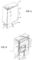
- FIGURE 1 illustrates a highlighted document 10, such as is produced according to the method of the present invention.
- the document comprises a substrate 11, preferably of paper, with words, symbols, or other indicia 12, 13.
- the indicia 12 is not highlighted, but the indicia 13 is highlighted according to the present invention.
- This is accomplished by applying a tone 15 over the indicia 13.
- the tone may be formed utilizing a dot screen, line screen, or the like. For example it may be formed utilizing the dots 17 which are black and spaced from each other so that they clearly highlight the indicia 13, but are far enough apart so that the underlying indicia 13 is readable.
- the tone is preferably formed from screens with about 30-65 lines per inch and with a density of about 10-22% (e.g. about 20%). While it is preferred that the tone be screened on, it may be printed in other conventional manners too.
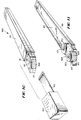
- the adhesive tape 15 comprises an elongated transparent substrate 19 (e.g. plastic) with the tone dots 17 or the like screened thereon. At predetermined places along the length of the substrate 19 are perforations 21, extending transversely to the dimension of elongation of the substrate 19 (and to the tape edge).
- An adhesive 22 is applied to one face of the tape 15, and preferably the tape is in the form of a roll 23.
- the adhesive may be of any conventional type, and may be a permanent adhesive such as is present on conventional pressure sensitive transparent tape, or it may be a readily releasable adhesive so that the tape 15 may be removed after it is applied (e.g. of the type utilized in the 3M "Post It Note”® products).
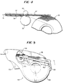
- a roll of tape 23 is utilized, preferably it is applied to the areas to be highlighted by tape dispenser 24. If the tape dispenser 24 is utilized perforations 21 are not necessary to effect separation of portions of tape.
- the tape dispenser 24 preferably comprises a housing 25 which includes means for mounting the tape roll 23 therein, which means may either be a portion of the housing 25 shaped to mount the roll, or a post for receiving the tape roll 23.
- the housing 25 is elongated in a dimension of elongation illustrated by arrows A in FIGURE 3, and the roll 23 is mounted for rotation about an axis generally perpendicular to the dimension A.
- the housing 25 may have a trigger 26 mounted therein, for pivotal movement about a pivot pin 27 mounted to the portion 28 of the housing 25 opposite that portion of the roll 23 from which the tape 15 is dispensed.
- Opposite from the roll 23 in the dimension of elongation A is means defining a tape dispensing opening 29 through which the tape 15 is dispensed.
- a rack 30 which has teeth 31 which engages a pinion 32 connected to a roller 33, the roller 33 comprising a driving roller rotatable about an axis parallel to the axis B.
- the roller 33 preferably cooperates with a stationary axis driven roller 35 mounted above the tape 15.
- Means are provided for defining a guide for the movement of the tape 15 from the roll 23 to the tape dispensing opening 29, for example the channel forming members 36. 37.
- the inner surfaces of the members 36, 37, and the outer surface of roller 33 are of low friction material (e.g. polytetrafluoroethylene) so that the tape 15 will not stick thereto.
- the roller 35 is of a frictional rubber material, or the like.
- the dispenser 24 also preferably comprises means for severing the tape (if perforated tape is not used).
- Such means preferably comprises the trigger 39 rotatable about pivot pin 40, with a movable blade 41 mounted thereto and cooperating with a stationary blade 42.
- the relative movement between the blades 41, 42 caused by depressing the trigger 39 severs the tape 15.
- Guidance of the tape out of the tape dispensing opening 29 is preferably provided by idler roller 44.
- the tape roll 23 may be inserted into the dispenser 24, and a used roll removed therefrom, merely by removing an entire side of the housing 25.
- the housing 25 and internal components appear as illustrated in FIGURE 3.
- the tape dispenser may take a variety of other forms too.
- Another exemplary form of tape dispenser is illustrated generally by reference numeral 124 in FIGURE 5.
- the dispenser of FIGURE 5 is like that of FIGURES 3 and 4 except for the mechanism for effecting rotation of the drive wheel.
- Components of the FIGURE 5 embodiment that are identical or similar in function to those of the FIGURES 3 and 4 embodiment are illustrated by the same reference numeral only preceded by a "1".
- the rack 130 with gear teeth 131 thereon is moved by arcuately moving the actuator 126.
- the teeth 131 engage pinion 132 on driving roller 133, which cooperates with upper pinch roller 135 to effect driving of the tape 15 within the dispenser.
- the cutting mechanism is actuated by trigger 139.
- the transfer sheet 50 comprises a substrate 52 of conventional transfer sheet material, which will receive ink thereon but then release the ink when it is rubbed.
- a number of spaced tone areas 53 are disposed on the substrate 52, e.g. screened thereon as by using a dot screen having between about (2-26) lines per cm (30-65 lpi) and a density of between about 10-22%.
- the tone areas 53 are quadrate (e.g. rectangular), and preferably they have a height 54 corresponding to the average height of a line of type (e.g. about one-sixth inch). Simply by rubbing on the surface of the substrate 52 opposite that to which the ink has been screened, the tone pattern 53 will transfer onto an underlying document, covering one line of type at a time.
- FIGURE 7 illustrates a transfer sheet much like that in FIGURE 6 except for the arrangement of the tone patterns.
- Like components in the FIGURE 7 embodiment to those in the FIGURE 6 embodiment are illustrated by the same reference numeral only preceded by a "1".
- the transfer sheet 150 includes a substrate 152 with the quadrate tone areas 153 thereon.
- the quadrate tone areas 153 are square in shape, and have a height 154 about the height of two lines of type (e.g. 0,84 cm (1/3 inch)).
- the applicator 60 comprises an outer housing 61 and an inner housing 62, which are relatively movable with respect to each other.
- a rolling drum print wheel 63 is mounted for pivotal movement about a horizontal axis by a shaft 64, which is guided by and reciprocal within elongated slot 65 formed in inner housing 62.
- the shaft 64 is affixed to the interior of the outer housing 61.
- the print wheel 63 has a plurality of projections 68 extending radially outwardly therefrom which.
- a bottom portion of the inner housing 62 extends outwardly from the outer housing 61 at the bottom, and has an arrow indicia 73 formed thereon to indicate the ink application area of the roller 63, with the cut out end surfaces 74 on the inner housing 62 defining the band that will be highlighted by the roller 63.
- the width of the roller 63 is an integer multiple of the height of a line of type (e.g. a multiple of one-sixth inch).
- Ink may be applied to the print wheel 63 utilizing the drum wheel 70 rotatable about axis 71, and supplied by ink from a felt pad (not shown) mounted within housing 72. Ink from the felt pad transfers to the drum wheel 70 and then onto the "dot" projection 68 to ultimately be applied to the document substrate.
- FIGURES 10 and 11 Another embodiment of a roller assembly for applying a tone to highlight indicia on a document is illustrated in FIGURES 10 and 11.
- FIGURES 10 and 11 structures comparable in function to those in the FIGURES 8 and 9 embodiment are indicated by the same reference numeral only preceded by a "1".
- the roller assembly 160 has a main elongated hollow casing having a body portion 161 and a removable cap 162 at one end of the body portion 161.
- the body portion is designed to look like a conventional highlighter which applies a liquid highlighting medium from a felt tip.
- a shoulder 81 is provided which cooperates with the removable cap 162, having pocket clip 80, to hold it in place in the closed position.
- a projecting portion 82 is provided extending outwardly from the shoulder 81 having an angled portion 83 terminating the projecting portion 82, with means defining an opening 84 in the angled portion 83.
- a print wheel 163, mounted for rotation about a pivot pin defining an axis 164, has tone applying projections 168 extending radially outwardly from the peripheral surface of print wheel 163.
- the mounting pin defining axis 164 mounts the print wheel 163 so that a portion of the peripheral portion thereof (with projections 168) extends outwardly from the angled portion 83 of the casing 161, through the opening 84 thereof.
- a drum wheel 170 is mounted for rotation about an axis 171 defined by a pivot pin, parallel to the axis of rotation 164 of the print wheel 163.
- the drum 170 is mounted within the hollow interior 85 of the casing 161, right at the junction of the projecting portion 82, so that the drum wheel 170 may provide somewhat of a seal at that juncture to prevent ink from leaking therepast.
- Ink may be provided in the hollow casing 85 either in liquid or semi-solid form, or impregnated in a felt material (not shown), so that as the print wheel 163 is moved along a document 10, ink is transferred from the drumwheel 170 to the projections 168, and a tone pattern is applied to the document, as illustrated in FIGURE 1.
- the length of the area to be highlighted is determined, and then the tape 15 is separated at the appropriate perforation 21 closest to that length.
- the tape is then applied directly over the indicia 13 (as seen in FIGURE 1) to highlight the indicia 13, while the indicia 13 is still readable.
- the document 10 is then electronically copied, as by a photocopier or transmission by facsimile machine, the highlighting 15, 17 also appearing on the electronically copied document while allowing the words and/or symbols comprising the indicia 13 to be clearly legible on such a copy. If adhesive 22 on the tape 15 is a releasable adhesive, then the tape 15 is removed from the original after copying.
- the trigger 26 is depressed which causes the gear teeth to rotate the gear 32, in turn driving the tape 15 from the roll 23 to the opening 29 by interaction between rollers 33, 35, the tape moving along the smooth surfaces of the guide channel 36, 37.
- the roller 44 is used to impress the tape 15 onto the document.
- the trigger 39 is actuated causing the blades 41, 42 to move toward each other, severing the tape 15.
- the operation is the same except that the actuator 126 is moved to advance the tape, the trigger 139 causing operation of the severing blades.
- the base 69 is placed over the line or lines to be highlighted. Then the upper housing 61 is moved downwardly which moves the print wheel 63 into contact with the document. The entire structure 60 is then moved horizontally parallel to the line or lines of text to be highlighted, causing the projections 68 to engage the document in a rolling action and to transfer ink to the document. Ink is supplied to the projections 68 by the roller 70, which in turn is provided ink by a felt pad in the structure 72. The area to which the ink will be applied is gauged by viewing the indicia 73 and the cut out portions 74.
Landscapes
- Physics & Mathematics (AREA)
- General Physics & Mathematics (AREA)
- Engineering & Computer Science (AREA)
- Multimedia (AREA)
- Signal Processing (AREA)
- Printers Characterized By Their Purpose (AREA)
- Printing Methods (AREA)
Claims (8)
- Verfahren zum Markieren von Dokumenten (10), um so deren Kennzeichnungsbereiche (13) in einer solchen Art hervorzuheben (15), daß die Hervorhebung reproduziert wird, wenn das Dokument elektronisch kopiert wird, gekennzeichnet durch die Schritte:(a) Aufbringen einer aus einem gepunkteten oder linierten Raster gebildeten Rastertönung (17), nur auf dem hervorzuhebenden Kennzeichnungsbereich (13) des Dokuments (11), so daß die Tönung während des Kopierens an ihrem Platz verbleibt, wobei die Tönung ausreichende Eigenschaften hat, so daß sie die Abschnitte des Dokuments, auf die sie aufgebracht ist, deutlich hervorhebt, während die darunterliegende Kennzeichnung deutlich lesbar bleibt; und(b) elektronisches Kopieren des Dokuments, so daß die Bereiche, auf die die Rastertönung aufgebracht wurde, auf der Kopie hervorgehoben sind, wobei die Kennzeichnungen, die unter der Rastertönung liegen, deutlich lesbar sind.
- Verfahren nach Anspruch 1, weiterhin dadurch gekennzeichnet, daß Schritt (b) durch Photokopieren oder durch Faksimileübertragung durchgeführt wird.
- Verfahren nach Anspruch 1, wobei die Tönung aus einem Stück Klebestreifen (15) besteht, und weiterhin dadurch gekennzeichnet, daß Schritt (a) durch Aufbringen des Streifens auf die hervorzuhebenden Bereiche durchgeführt wird.
- Verfahren nach Anspruch 3, wobei sich der Streifen auf einer Rolle (23) in einem Streifenspender (24, 124) befindet und an Stellen mit vorbestimmtem Abstand entlang seiner Länge perforiert ist, und weiterhin dadurch gekennzeichnet, daß Schritt (a) durchgeführt wird durch: Bestimmen der notwendigen Länge des Streifens; Abtrennen des Streifens an der nächstgelegenen Perforation zur gewünschten Länge; und Abgeben des Streifens vom Spender auf das Dokument (10).
- Verfahren nach Anspruch 1, weiterhin dadurch gekennzeichnet, daß Schritt (a) durchgeführt wird, indem Tinte direkt auf die hervorzuhebenden Bereiche des Dokuments aufgetragen wird.
- Verfahren nach Anspruch 5, wobei eine Tintenapplikatorwalze (63, 163) ein Tönungsmuster (68, 168) darauf hat und in einem Gehäuse (62, 162) um eine horizontale Achse (64, 164) drehbar gehaltert ist und in Anlage an einen Tintenapplikator (70, 170) kommen kann, und weiterhin dadurch gekennzeichnet, daß Schritt (a) durchgeführt wird, indem die Walze mit dem Tönungsmuster über die hervorzuhebenden Dokumentbereiche gerollt wird, um die Tinte aufzutragen.
- Verfahren nach Anspruch 1, wobei die Tönung auf einem Übertragungsbogen (52, 152) vorgesehen ist, und weiterhin dadurch gekennzeichnet, daß Schritt (a) durchgeführt wird, indem der Übertagungsbogen über dem hervorzuhebenden Dokumentbereich plaziert wird, und indem auf dem Übertragungsbogen in dem Bereich, in dem die Tönung (53, 153) auf den Bereich übertragen werden soll, gerieben wird.
- Verfahren nach den vorhergehenden Ansprüchen, weiterhin dadurch gekennzeichnet, daß Schritt (a) durchgeführt wird, indem eine Tönung mit ungefähr 12-26 Linien pro cm (30-65 Linien per Inch) und einer Dichte von ungefähr 10-22 % aufgebracht wird.
Priority Applications (4)
| Application Number | Priority Date | Filing Date | Title |
|---|---|---|---|
| US07/321,732 US5098817A (en) | 1989-03-10 | 1989-03-10 | Highlighting for photocopiers and facsimile machines |
| EP90107790A EP0453594B1 (de) | 1989-03-10 | 1990-04-24 | Hervorhebungsverfahren für Fotokopier- und Faksimilegeräte |
| DE69012100T DE69012100D1 (de) | 1990-04-24 | 1990-04-24 | Hervorhebungsverfahren für Fotokopier- und Faksimilegeräte. |
| AT90107790T ATE110862T1 (de) | 1990-04-24 | 1990-04-24 | Hervorhebungsverfahren für fotokopier- und faksimilegeräte. |
Applications Claiming Priority (2)
| Application Number | Priority Date | Filing Date | Title |
|---|---|---|---|
| US07/321,732 US5098817A (en) | 1989-03-10 | 1989-03-10 | Highlighting for photocopiers and facsimile machines |
| EP90107790A EP0453594B1 (de) | 1989-03-10 | 1990-04-24 | Hervorhebungsverfahren für Fotokopier- und Faksimilegeräte |
Publications (2)
| Publication Number | Publication Date |
|---|---|
| EP0453594A1 EP0453594A1 (de) | 1991-10-30 |
| EP0453594B1 true EP0453594B1 (de) | 1994-08-31 |
Family
ID=26125129
Family Applications (1)
| Application Number | Title | Priority Date | Filing Date |
|---|---|---|---|
| EP90107790A Expired - Lifetime EP0453594B1 (de) | 1989-03-10 | 1990-04-24 | Hervorhebungsverfahren für Fotokopier- und Faksimilegeräte |
Country Status (2)
| Country | Link |
|---|---|
| US (1) | US5098817A (de) |
| EP (1) | EP0453594B1 (de) |
Families Citing this family (15)
| Publication number | Priority date | Publication date | Assignee | Title |
|---|---|---|---|---|
| US5417505A (en) * | 1989-03-10 | 1995-05-23 | Voorhees; Scott W. | Tone pattern applying instrument |
| US5291243A (en) * | 1993-02-05 | 1994-03-01 | Xerox Corporation | System for electronically printing plural-color tamper-resistant documents |
| US5568248A (en) * | 1994-12-05 | 1996-10-22 | Xerox Corporation | Black and white reproducible pattern highlight color printing |
| US5701401A (en) * | 1996-10-02 | 1997-12-23 | Xerox Corporation | Printing black and white reproducible color documents |
| US6179485B1 (en) | 1996-11-18 | 2001-01-30 | Xerox Corporation | Printing black and white reproducible colored stroke documents |
| US6169607B1 (en) | 1996-11-18 | 2001-01-02 | Xerox Corporation | Printing black and white reproducible colored test documents |
| US6373602B1 (en) * | 1999-02-12 | 2002-04-16 | Canon Kabushiki Kaisha | Facsimile transmission of highlight information |
| US20050142308A1 (en) * | 2005-03-15 | 2005-06-30 | Darla Thorpe | Highlighter strips |
| US8179565B2 (en) * | 2005-09-08 | 2012-05-15 | Go Daddy Operating Company, LLC | Document color and shades of gray optimization using outlining |
| US7777917B2 (en) * | 2005-09-08 | 2010-08-17 | The Go Daddy Group, Inc. | Document color and shades of gray optimization using solid monochrome colors |
| US8115977B2 (en) * | 2005-09-08 | 2012-02-14 | Go Daddy Operating Company, LLC | Document color and shades of gray optimization using monochrome patterns |
| US7502135B2 (en) * | 2005-09-08 | 2009-03-10 | The Go Daddy Group, Inc. | Document color and shades of gray optimization using dithered monochrome surfaces |
| US7767295B2 (en) * | 2006-10-30 | 2010-08-03 | Eric Steinzor | Reinforced packing tape with tamper indicator |
| JP5443085B2 (ja) | 2009-07-28 | 2014-03-19 | 株式会社エルモ社 | 資料提示装置 |
| US8864177B2 (en) * | 2011-11-23 | 2014-10-21 | Esselte Corporation | Movable highlight strip |
Family Cites Families (12)
| Publication number | Priority date | Publication date | Assignee | Title |
|---|---|---|---|---|
| US3152528A (en) * | 1963-09-23 | 1964-10-13 | Xerox Corp | Document carrier |
| US3942621A (en) * | 1970-04-28 | 1976-03-09 | Mac Karlan | Method of and article for masking |
| FR2278102A1 (fr) * | 1974-07-11 | 1976-02-06 | Berthold Ag H | Procede d'execution de modifications sur les films de photocomposition |
| US4045219A (en) * | 1976-01-07 | 1977-08-30 | Xerox Corporation | Method of reproducing color highlighted documents |
| US4118122A (en) * | 1977-02-07 | 1978-10-03 | Xerox Corporation | Method of rendering objects uncopyable by photocopy processes |
| US4632529A (en) * | 1984-03-16 | 1986-12-30 | Wilfred Levin | Accessory for use with an overhead projector |
| JPS60257294A (ja) * | 1984-06-04 | 1985-12-19 | 沖電気工業株式会社 | エンドレス状の筆記媒体を備えた電子黒板装置 |
| JPS60257295A (ja) * | 1984-06-04 | 1985-12-19 | 沖電気工業株式会社 | 電子黒板装置 |
| JPS61175033A (ja) * | 1985-01-31 | 1986-08-06 | 聖城 健嘉 | コピ−修正用テ−プ |
| US4777510A (en) * | 1986-12-11 | 1988-10-11 | Eastman Kodak Company | Copying apparatus and method with editing and production control capability |
| US4862217A (en) * | 1985-12-16 | 1989-08-29 | Eastman Kodak Company | Copying apparatus and method with editing and production control capability |
| IT209813Z2 (it) * | 1987-01-08 | 1988-11-04 | Incas Int Carbon Solvent Spa | Nastro adesivo fluorescente atto all'impiego com evidenziatore. |
-
1989
- 1989-03-10 US US07/321,732 patent/US5098817A/en not_active Expired - Fee Related
-
1990
- 1990-04-24 EP EP90107790A patent/EP0453594B1/de not_active Expired - Lifetime
Also Published As
| Publication number | Publication date |
|---|---|
| US5098817A (en) | 1992-03-24 |
| EP0453594A1 (de) | 1991-10-30 |
Similar Documents
| Publication | Publication Date | Title |
|---|---|---|
| EP0453594B1 (de) | Hervorhebungsverfahren für Fotokopier- und Faksimilegeräte | |
| JP4133401B2 (ja) | テープ保持ケース及びそれを用いた印字装置 | |
| FR2387776A1 (fr) | Appareil d'impression par gouttes d'encre pour copier ou reproduire des documents | |
| EP0138287A2 (de) | Verfahren zur Fabrikation von "overhead" Transparenten und Montage dieser Transparente | |
| FR2939358A1 (fr) | Dispositif de timbrage | |
| US5855083A (en) | Erasable sign | |
| US5359931A (en) | Highlighting for photocopiers and facsimile machines | |
| US5417505A (en) | Tone pattern applying instrument | |
| AU7060696A (en) | Apparatus for printing graphic images on sheet material having an ink web cassette with constant web tension | |
| CA2016650A1 (en) | Highlighting for photocopiers and facsimile machines | |
| US5778776A (en) | Stencil stamp unit | |
| KR960001865A (ko) | 주문제작 필름 | |
| US20100124626A1 (en) | Method and printing sheet for the production of hand stamps | |
| US4595305A (en) | Ribbon cassette | |
| JP2583637B2 (ja) | 文書のハイライト方法及びプリント輪 | |
| US4364678A (en) | Reinkable ribbon cartridge | |
| GB2010186A (en) | Apparatus for producing printed strips from a web of paper | |
| EP1056067A2 (de) | Papierwaren und Etikettenhüllen | |
| US4470712A (en) | Hand held printer and printing guide | |
| KR200294664Y1 (ko) | 용지공급방향을 표시하는 이미지를 갖는 라벨 | |
| JPS6117471Y2 (de) | ||
| JPS61192664A (ja) | ラベルマ−カ− | |
| KR960009503Y1 (ko) | 기계기구용 표지판 | |
| KR200141750Y1 (ko) | 프린트기를 이용한 디스프레이장치 | |
| JPS607587Y2 (ja) | 原稿キャリアシ−ト |
Legal Events
| Date | Code | Title | Description |
|---|---|---|---|
| PUAI | Public reference made under article 153(3) epc to a published international application that has entered the european phase |
Free format text: ORIGINAL CODE: 0009012 |
|
| 17P | Request for examination filed |
Effective date: 19910601 |
|
| AK | Designated contracting states |
Kind code of ref document: A1 Designated state(s): AT BE CH DE DK ES FR GB GR IT LI LU NL SE |
|
| 17Q | First examination report despatched |
Effective date: 19921216 |
|
| GRAA | (expected) grant |
Free format text: ORIGINAL CODE: 0009210 |
|
| AK | Designated contracting states |
Kind code of ref document: B1 Designated state(s): AT BE CH DE DK ES FR GB GR IT LI LU NL SE |
|
| PG25 | Lapsed in a contracting state [announced via postgrant information from national office to epo] |
Ref country code: IT Free format text: LAPSE BECAUSE OF FAILURE TO SUBMIT A TRANSLATION OF THE DESCRIPTION OR TO PAY THE FEE WITHIN THE PRE;WARNING: LAPSES OF ITALIAN PATENTS WITH EFFECTIVE DATE BEFORE 2007 MAY HAVE OCCURRED AT ANY TIME BEFORE 2007. THE CORRECT EFFECTIVE DATE MAY BE DIFFERENT FROM THE ONE RECORDED.SCRIBED TIME-LIMIT Effective date: 19940831 Ref country code: BE Effective date: 19940831 Ref country code: LI Effective date: 19940831 Ref country code: NL Effective date: 19940831 Ref country code: GR Free format text: LAPSE BECAUSE OF FAILURE TO SUBMIT A TRANSLATION OF THE DESCRIPTION OR TO PAY THE FEE WITHIN THE PRESCRIBED TIME-LIMIT Effective date: 19940831 Ref country code: AT Effective date: 19940831 Ref country code: CH Effective date: 19940831 Ref country code: DK Effective date: 19940831 Ref country code: FR Effective date: 19940831 Ref country code: ES Free format text: THE PATENT HAS BEEN ANNULLED BY A DECISION OF A NATIONAL AUTHORITY Effective date: 19940831 |
|
| REF | Corresponds to: |
Ref document number: 110862 Country of ref document: AT Date of ref document: 19940915 Kind code of ref document: T |
|
| REF | Corresponds to: |
Ref document number: 69012100 Country of ref document: DE Date of ref document: 19941006 |
|
| PG25 | Lapsed in a contracting state [announced via postgrant information from national office to epo] |
Ref country code: SE Effective date: 19941130 |
|
| PG25 | Lapsed in a contracting state [announced via postgrant information from national office to epo] |
Ref country code: DE Effective date: 19941201 |
|
| REG | Reference to a national code |
Ref country code: CH Ref legal event code: PL |
|
| EN | Fr: translation not filed | ||
| NLV1 | Nl: lapsed or annulled due to failure to fulfill the requirements of art. 29p and 29m of the patents act | ||
| PGFP | Annual fee paid to national office [announced via postgrant information from national office to epo] |
Ref country code: GB Payment date: 19950413 Year of fee payment: 6 |
|
| PG25 | Lapsed in a contracting state [announced via postgrant information from national office to epo] |
Ref country code: LU Free format text: LAPSE BECAUSE OF NON-PAYMENT OF DUE FEES Effective date: 19950430 |
|
| PLBE | No opposition filed within time limit |
Free format text: ORIGINAL CODE: 0009261 |
|
| STAA | Information on the status of an ep patent application or granted ep patent |
Free format text: STATUS: NO OPPOSITION FILED WITHIN TIME LIMIT |
|
| 26N | No opposition filed | ||
| PG25 | Lapsed in a contracting state [announced via postgrant information from national office to epo] |
Ref country code: GB Effective date: 19960424 |
|
| GBPC | Gb: european patent ceased through non-payment of renewal fee |
Effective date: 19960424 |