EP0453608A1 - Procédé pour la recomposition automatique d'informations de numérotation sélectionnées et continues dans une mémoire - Google Patents
Procédé pour la recomposition automatique d'informations de numérotation sélectionnées et continues dans une mémoire Download PDFInfo
- Publication number
- EP0453608A1 EP0453608A1 EP90108056A EP90108056A EP0453608A1 EP 0453608 A1 EP0453608 A1 EP 0453608A1 EP 90108056 A EP90108056 A EP 90108056A EP 90108056 A EP90108056 A EP 90108056A EP 0453608 A1 EP0453608 A1 EP 0453608A1
- Authority
- EP
- European Patent Office
- Prior art keywords
- information
- dialing
- dialing information
- communication terminal
- input means
- Prior art date
- Legal status (The legal status is an assumption and is not a legal conclusion. Google has not performed a legal analysis and makes no representation as to the accuracy of the status listed.)
- Granted
Links
- 238000000034 method Methods 0.000 title claims description 9
- 238000004891 communication Methods 0.000 claims abstract description 42
- 230000003287 optical effect Effects 0.000 claims 1
- 230000011664 signaling Effects 0.000 description 11
- 238000006243 chemical reaction Methods 0.000 description 6
- 230000006870 function Effects 0.000 description 5
- 238000005516 engineering process Methods 0.000 description 4
- 238000010586 diagram Methods 0.000 description 3
- 239000003550 marker Substances 0.000 description 3
- 230000005540 biological transmission Effects 0.000 description 2
- 230000003213 activating effect Effects 0.000 description 1
- 239000008186 active pharmaceutical agent Substances 0.000 description 1
- 230000001174 ascending effect Effects 0.000 description 1
- 238000013461 design Methods 0.000 description 1
- 238000011161 development Methods 0.000 description 1
- 230000000977 initiatory effect Effects 0.000 description 1
- 238000011017 operating method Methods 0.000 description 1
- 230000033764 rhythmic process Effects 0.000 description 1
Images


Classifications
-
- H—ELECTRICITY
- H04—ELECTRIC COMMUNICATION TECHNIQUE
- H04M—TELEPHONIC COMMUNICATION
- H04M1/00—Substation equipment, e.g. for use by subscribers
- H04M1/56—Arrangements for indicating or recording the called number at the calling subscriber's set
-
- H—ELECTRICITY
- H04—ELECTRIC COMMUNICATION TECHNIQUE
- H04M—TELEPHONIC COMMUNICATION
- H04M1/00—Substation equipment, e.g. for use by subscribers
- H04M1/26—Devices for calling a subscriber
- H04M1/27—Devices whereby a plurality of signals may be stored simultaneously
- H04M1/274—Devices whereby a plurality of signals may be stored simultaneously with provision for storing more than one subscriber number at a time, e.g. using toothed disc
- H04M1/2745—Devices whereby a plurality of signals may be stored simultaneously with provision for storing more than one subscriber number at a time, e.g. using toothed disc using static electronic memories, e.g. chips
- H04M1/27467—Methods of retrieving data
- H04M1/2747—Scrolling on a display
Definitions
- Communication terminals in particular telephony devices, have been equipped with redial functions for some time.
- the dialing information formed by dialing keys is stored automatically or by additional key input and the dialing information formed by speed dialing, name or direct call keys, if provided, predominantly by key input for a later redial in a redial memory. If there is no connection to the communication terminal determined by the dialing information - busy or unoccupied - the dialing information stored in the redial memory can be transmitted to the assigned communication system at any time by pressing a redial button in the sense of a renewed attempt to establish a connection.
- this redialing method only the last dialing information formed in the case of automatic storage and only one dialing information in each case for the establishment of a connection in the sense of a redialing when stored by key input.
- the object on which the invention is based is to design further dialing information already formed in the respective communication terminals in a redial process.
- the object is achieved on the basis of a communication terminal connected to a communication system in accordance with the preamble of claim 1 by its characterizing features.
- the essential aspect of the invention is to be seen in the fact that a plurality of dialing information items which have been input in the event of unsuccessful or successful connection attempts are recorded in a dialing information storage device and by means of a search input means - e.g. B. search button - the recorded dialing information can be controlled one after the other in the sense of a search for a specific recorded dialing information, each controlled recorded dialing information being displayed optically and / or acoustically in the communication terminal.
- a search input means arranged on the communication terminal - e.g. B. Redial button - a connection is established to the dialing information currently displayed optically or acoustically on the communication terminal.
- the dialing information arriving at the communication terminal can also be stored and marked in the dialing information storage device.
- the prerequisite for this is - this is the case in digital communication networks, in particular in the integrated data and telephone network (ISDN) - that the dialing information of the calling communication terminal is transmitted as part of a connection setup.
- ISDN integrated data and telephone network
- the dialing information is stored cyclically in a dialing information storage device limited with regard to the number of the partial storage areas, in the partial storage area order - see claim 3.
- the partial storage areas of the dialing information storage device are activated cyclically in the partial storage area order using the search input means - See claim 4.
- the number of partial memory areas is to be matched or limited on the one hand to the highest possible number of storable selection information and on the other hand to the shortest possible search times.
- the number of partial memory areas should, for. B. be dimensioned such that the search time using the input means does not significantly exceed the input time for an item of information to be entered.
- a marking symbol can be controlled from displayed election information to election information - see claim 5.
- the number of displayable election information is limited here by the display capacity of the display device.
- the election information is z. B. transmitted in groups from the partial storage areas to the display device and displayed there. If the marker symbol is driven to the upper or lower display area using the search button, the following selection information is, for example, in turn transmitted in groups to the display device and displayed there.
- the search input means e.g. B. search button, the marker icon is controlled to the desired election information. After pressing the redial key, the marked dialing information is transmitted to the communication system in the sense of establishing a connection.
- a display device AZE is provided for the display of digits, text and the dialing information.
- This display device AZE is implemented, for example, by an LCD display. It is also used to enter signaling and dialing information a keypad TF is provided.
- This keypad TF contains the numerical keys (not shown in detail) for entering dialing information and further keys for entering additional functions.
- One of these keys equipped with an additional function is a redial key WWT and a search key ST.
- the search process is initiated in a dialing information storage device. During this search, the recorded voting information is stored for a predetermined period of time, e.g. B.
- connection setup with the displayed dialing information is initiated after pressing the redial key WWT.
- the dialing information is led via a connection line ASL to a communication system KA and evaluated there for the further establishment of the connection.
- the central device for controlling the subscriber operating procedures, for controlling all acoustic signals to be transmitted in the communication terminal KE and for controlling the signaling with the communication system KA is implemented by a microprocessor system ⁇ P.
- this microprocessor system ⁇ P can be formed by a Siemens microprocessor SAB 80C31.
- the microprocessor system ⁇ P is connected to a program memory PS and a data memory DS via a local bus LB formed by control, address and data lines.
- the program memory PS implemented in ROM memory technology is designed, for example, for a program comprising a maximum of 64 KB.
- the 64 KByte data memory for example, can also contain half a ROM memory technology - for fixed data, parameter data and tables - and half a RAM memory technology - for example for storing user-specific data.
- RAM there is also the election information memory or the election information storage device Contain WIS, which has several partial storage areas TS.
- the microprocessor system ⁇ P also has a serial bus interface. This serial bus interface is connected to a control panel microprocessor system B ⁇ P via the serial bus SB.
- the auxiliary devices BSE connected to the communication terminal KE are also operated via this serial bus SB.
- the coded information generated by the control elements or keys of the keypad TF is recognized, serially transmitted to the microprocessor system ⁇ P via the serial bus SB and there for signaling information and operator guidance information - for example for light-emitting diodes, tones and displays in a display device - processed.
- a display device AZE is also connected to the local bus LB.
- the display device AZE is implemented, for example, by an LC display (two lines of 24 characters each). This LC display is used to display digits and plain text as well as dialing information.
- the communication terminal KE is connected to a subscriber line ASL via a connection device AE.
- the communication terminal KE communicates with a communication system KA via this subscriber line ASL.
- the 64 KByte / s messages and the 8 KByte / s signaling information are transmitted bidirectionally via the subscriber line ASL.
- the signaling information transmitted in the signaling channel is structured in accordance with the OSI reference model.
- the lower three protocol layers of the seven abstracted protocol layers of the OSI reference model are implemented.
- the protocol layers used for the communication terminals - communication system signaling - are defined as physical layer (layer 1), as data link layer (layer 2) and as a network layer (layer 3).
- the physical layer also referred to as the physical level, does this Transmission of the information in the message and signaling channels simultaneously in both directions. This includes activating, deactivating and operating the communication terminal KE.
- the data link layer takes over the secure transmission of the signaling information between the communication system KA and the communication terminal KE for the subsequent network layer.
- the network layer serves to set up, monitor and clear the communication connections as well as to control and monitor the performance features supported by the communication system KA.
- the functions of the physical layer (layer 1) and the control of the microprocessor system ⁇ P are essentially implemented in the connection device AE.
- the signaling information separated in the connection device AE from information transmitted via the connection line ASL is processed in accordance with the local bus and transmitted to the microprocessor system ⁇ P via the local bus LB. In the microprocessor system, this signaling information is further processed in accordance with the functions assigned to the data link layer and network layer and the corresponding reactions - e.g. B. control of output units - initiated.
- the message information separated in the connection device AE reaches an analog / digital conversion device A / D. In this, analog voice signals are formed from the digitized message or voice signals output by the connection device AE. The analog voice signals arriving at a further input of the analog / digital conversion device A / D are converted into digital voice signals.
- the analog voice signals reach a third input E3 of an acoustic device AKE via a corresponding connection.
- the acoustic device AKE is composed of an acoustic coupler AK and a control device ASE.
- the acoustic coupler AK transmits the analog signals arriving from the analog / digital conversion device A / D either only to a first output A1 or to the first and to a second output A1, A2.
- Output is A1 connected to the handset of the communication terminal KE via a preamplifier VV.
- the analog voice signals are routed via the preamplifier VV to an earpiece arranged in the handset HA.
- the voice signals emitted by a microphone arranged in the handset HA reach a first input E1 of the acoustic coupler AK via the preamplifier VV.
- the analog voice signals are conveyed through the acoustic coupler AK to a third output A3 connected to the analog / digital conversion device A / D.
- These analog voice signals are converted into digital signals in the analog / digital conversion device A / D and inserted into the message stream transmitted to the connection line ASL in the connection device AE.
- the analog voice signals arriving at the third input E3 are simultaneously led to a second output A2 of the acoustic coupler AK. From there, the analog voice signals pass through an amplifier V to a loudspeaker LS arranged in the communication terminal KE.
- the control device ASE arranged in the acoustic device AKE is connected both to the acoustic coupler AK and to the local bus LB. In this control device ASE, the control commands transmitted by the microprocessor system ⁇ P via the local bus LB are converted into information by means of which the connection paths in the acoustic coupler AK are set.
- the acoustic coupler AK is implemented, for example, by analog crosspoints implemented in CMOS technology.
- the control device ASE controls a ring tone generator RT which, depending on the control, generates different ring tones with corresponding ringing rhythms. These ringing tones are transmitted to the handset HA and / or the loudspeaker LS via the acoustic coupler AK under the control of the control device ASE.
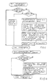
- 3 and 4 show the self-explanatory program flow diagrams for searching for dialing information in the dialing information storage device WIS and initiating a connection setup with the dialing information sought by actuation the redial key WWT.
- the program that realizes these program sequences is stored in the program memory PS of the communication terminal KE.
- the dialing information output by the dialing buttons is recognized in the control panel microprocessor system B ⁇ P, the corresponding dialing information is coded and transmitted via the microprocessor ⁇ P to the respective partial memory areas TS of the dialing information storage device WIS.
- the election information is, for example, successively, for. B. cyclically in memory addresses in descending order, stored in the election information storage device WIS. Analogously to this, as shown in FIG. 3, the election information from the election information storage device WIS can be controlled, read and displayed in the display device AZE cyclically, in ascending order in memory addresses using the search key ST.
- the selection information can also be transmitted in groups to the display device AZE, displayed there and selected using the search key ST or a marking symbol.
- the display duration of the selected information is implemented by a counting loop. If, for example, the query cycle is initialized every 25 ms for all keys, the display duration is 20 times 25 ms, i.e. 500 ms.
- the display duration can be determined by varying the maximum counter value. This maximum counter value can be determined individually by a corresponding entry or by stored information, for example. B. in the database.
Landscapes
- Engineering & Computer Science (AREA)
- Signal Processing (AREA)
- Telephonic Communication Services (AREA)
Priority Applications (2)
| Application Number | Priority Date | Filing Date | Title |
|---|---|---|---|
| EP90108056A EP0453608B2 (fr) | 1990-04-27 | 1990-04-27 | Procédé pour la recomposition automatique d'informations de numérotation sélectionnées et continues dans une mémoire |
| DE59006843T DE59006843D1 (de) | 1990-04-27 | 1990-04-27 | Verfahren zur Wahlwiederholung von aus einer Wahlinformationsspeichereinrichtung auswählbaren Wahlinformationen. |
Applications Claiming Priority (1)
| Application Number | Priority Date | Filing Date | Title |
|---|---|---|---|
| EP90108056A EP0453608B2 (fr) | 1990-04-27 | 1990-04-27 | Procédé pour la recomposition automatique d'informations de numérotation sélectionnées et continues dans une mémoire |
Publications (3)
| Publication Number | Publication Date |
|---|---|
| EP0453608A1 true EP0453608A1 (fr) | 1991-10-30 |
| EP0453608B1 EP0453608B1 (fr) | 1994-08-17 |
| EP0453608B2 EP0453608B2 (fr) | 1998-11-18 |
Family
ID=8203923
Family Applications (1)
| Application Number | Title | Priority Date | Filing Date |
|---|---|---|---|
| EP90108056A Expired - Lifetime EP0453608B2 (fr) | 1990-04-27 | 1990-04-27 | Procédé pour la recomposition automatique d'informations de numérotation sélectionnées et continues dans une mémoire |
Country Status (2)
| Country | Link |
|---|---|
| EP (1) | EP0453608B2 (fr) |
| DE (1) | DE59006843D1 (fr) |
Cited By (3)
| Publication number | Priority date | Publication date | Assignee | Title |
|---|---|---|---|---|
| DE4135384C1 (fr) * | 1991-10-26 | 1993-06-09 | Friedrich Merk-Telefonbau Gmbh, 8000 Muenchen, De | |
| DE4423789A1 (de) * | 1994-07-01 | 1996-08-08 | Deutsche Telekom Ag | Verfahren und Anordnung zur Wahlwiederholung bei Telekommunikationseinrichtungen |
| EP0876037A3 (fr) * | 1997-04-30 | 1999-04-14 | Koninklijke Philips Electronics N.V. | Terminal, procédé de rappel automatique et système de télécommunications |
Citations (4)
| Publication number | Priority date | Publication date | Assignee | Title |
|---|---|---|---|---|
| DE3630471A1 (de) * | 1986-09-06 | 1988-04-21 | Vierling Werner | Schaltungsanordnung zur anzeige der rufnummer eines rufenden teilnehmers beim fernsprechapparat des gerufenen teilnehmers |
| EP0268739A2 (fr) * | 1986-11-25 | 1988-06-01 | Robert Bosch Gmbh | Méthode d'enregistrement et de choix de numéros d'appel |
| US4870677A (en) * | 1987-09-04 | 1989-09-26 | Copytele, Inc. | Data/facsimile telephone subset apparatus incorporating electrophoretic displays |
| US4908853A (en) * | 1987-05-29 | 1990-03-13 | Canon Kabushiki Kaisha | Dialing apparatus |
-
1990
- 1990-04-27 EP EP90108056A patent/EP0453608B2/fr not_active Expired - Lifetime
- 1990-04-27 DE DE59006843T patent/DE59006843D1/de not_active Expired - Lifetime
Patent Citations (4)
| Publication number | Priority date | Publication date | Assignee | Title |
|---|---|---|---|---|
| DE3630471A1 (de) * | 1986-09-06 | 1988-04-21 | Vierling Werner | Schaltungsanordnung zur anzeige der rufnummer eines rufenden teilnehmers beim fernsprechapparat des gerufenen teilnehmers |
| EP0268739A2 (fr) * | 1986-11-25 | 1988-06-01 | Robert Bosch Gmbh | Méthode d'enregistrement et de choix de numéros d'appel |
| US4908853A (en) * | 1987-05-29 | 1990-03-13 | Canon Kabushiki Kaisha | Dialing apparatus |
| US4870677A (en) * | 1987-09-04 | 1989-09-26 | Copytele, Inc. | Data/facsimile telephone subset apparatus incorporating electrophoretic displays |
Non-Patent Citations (1)
| Title |
|---|
| PTR/PHILIPS TELECOMMUN. & DATA SYSTEMS REVIEW, Band 47, Nr. 1, M{rz 1989, pages 1-14, Hilversum, NL; C.M. KLIK: "The SOPHO-SET family of digital telephone terminals for SOPHO-S PABXs" * |
Cited By (4)
| Publication number | Priority date | Publication date | Assignee | Title |
|---|---|---|---|---|
| DE4135384C1 (fr) * | 1991-10-26 | 1993-06-09 | Friedrich Merk-Telefonbau Gmbh, 8000 Muenchen, De | |
| DE4423789A1 (de) * | 1994-07-01 | 1996-08-08 | Deutsche Telekom Ag | Verfahren und Anordnung zur Wahlwiederholung bei Telekommunikationseinrichtungen |
| DE4423789C2 (de) * | 1994-07-01 | 1998-02-05 | Deutsche Telekom Ag | Verfahren zur Wahlwiederholung bei Telekommunikationseinrichtungen |
| EP0876037A3 (fr) * | 1997-04-30 | 1999-04-14 | Koninklijke Philips Electronics N.V. | Terminal, procédé de rappel automatique et système de télécommunications |
Also Published As
| Publication number | Publication date |
|---|---|
| DE59006843D1 (de) | 1994-09-22 |
| EP0453608B1 (fr) | 1994-08-17 |
| EP0453608B2 (fr) | 1998-11-18 |
Similar Documents
| Publication | Publication Date | Title |
|---|---|---|
| DE2741616C2 (fr) | ||
| DE69531052T2 (de) | Telekommunikationsverfahren und eine zu seiner Durchführung geeignete Vorrichtung | |
| DE4136138A1 (de) | Multifunktionales telefonsystem mit spracherkennungs- und auswerteeinrichtung sowie ein verfahren zum betrieb dieses telefonsystems | |
| EP0929200A2 (fr) | Procédé et dispositif pour fournir le service de sélection directe à l'arrivée dans des centraux de télécommunications | |
| EP0517942B1 (fr) | Procédé de modification d'une procédure de signalisation mise en oeuvre dans un terminal de télécommunication | |
| EP0453608B1 (fr) | Procédé pour la recomposition automatique d'informations de numérotation sélectionnées et continues dans une mémoire | |
| DE1762884C3 (de) | Schaltungsanordnung zur Bereitstellung von Sonderdiensten in Fernmelde-, insbesondere Fernsprechvermittlungsanlagen | |
| EP0439065A2 (fr) | Poste d'abonné pourvu d'une mémoire intermédiaire associée à une fonction de numérotation abrégée | |
| DE3932686C2 (de) | Verfahren zur Aktivierung der Wahlinformationsabgabe für die Verbindungsherstellung in einem rechnergesteuerten Kommunikationssystem | |
| DE3825898C2 (de) | Fernsprechendgerät mit Funktionstasten | |
| DE4232272A1 (de) | Verfahren und Anordnung zur Anzeige von Rufnummern an Fernmeldeendgeräten einer Fernmeldenebenstellenanlage | |
| EP0720340A2 (fr) | Méthode d'interception d'appels téléphoniques en réception | |
| CH631849A5 (de) | Verfahren zur herstellung einer verbindung ueber ein fernsprechwaehlnetz fuer den bildschirmtextempfang. | |
| DE4020618C2 (de) | Verfahren zur Signalisierung von Fernsprech-Rückrufverbindungen | |
| DE19716316A1 (de) | Telekommunikationseinrichtung und Verfahren zu ihrem Betrieb | |
| EP0758829B1 (fr) | Méthode pour améliorer le fonctionnement d'un système de communication à commande programmée | |
| DE4006048C2 (fr) | ||
| DE19809835C2 (de) | Gezielte Anrufselektierung "Distinctive Call" | |
| DE3236500C2 (fr) | ||
| EP0758828B1 (fr) | Méthode pour améliorer le fonctionnement d'un système de communication à commande programmée | |
| DE19818513B4 (de) | Verfahren zum Aufbau einer Verbindung durch ein an ein Kommunikationssystem angeschlossenes Endgerät | |
| DE3328059A1 (de) | Verfahren zur empfangsseitigen auswahl von ueber eine vermittlungsstelle einer fernmelde- bzw. fernsprechanlage laufende daten- bzw. sprechverbindungen | |
| EP1098499B1 (fr) | Appareil et procédé de télécommunication | |
| DE4113366C2 (fr) | ||
| DE19948090B4 (de) | Verfahren zum Anschliessen eines Endgerätes an eine Telekommunikationsanlage sowie zugehörige elektronische Baueinheiten |
Legal Events
| Date | Code | Title | Description |
|---|---|---|---|
| PUAI | Public reference made under article 153(3) epc to a published international application that has entered the european phase |
Free format text: ORIGINAL CODE: 0009012 |
|
| 17P | Request for examination filed |
Effective date: 19901205 |
|
| AK | Designated contracting states |
Kind code of ref document: A1 Designated state(s): AT BE CH DE DK ES FR GB GR IT LI LU NL SE |
|
| RBV | Designated contracting states (corrected) |
Designated state(s): BE DE FR GB IT NL |
|
| 17Q | First examination report despatched |
Effective date: 19940126 |
|
| GRAA | (expected) grant |
Free format text: ORIGINAL CODE: 0009210 |
|
| AK | Designated contracting states |
Kind code of ref document: B1 Designated state(s): BE DE FR GB IT NL |
|
| REF | Corresponds to: |
Ref document number: 59006843 Country of ref document: DE Date of ref document: 19940922 |
|
| ITF | It: translation for a ep patent filed | ||
| GBT | Gb: translation of ep patent filed (gb section 77(6)(a)/1977) |
Effective date: 19941024 |
|
| ET | Fr: translation filed | ||
| PLBI | Opposition filed |
Free format text: ORIGINAL CODE: 0009260 |
|
| 26 | Opposition filed |
Opponent name: INTERESSENGEMEINSCHAFT FUER RUNDFUNKSCHUTZRECHTE G Effective date: 19950517 |
|
| NLR1 | Nl: opposition has been filed with the epo |
Opponent name: INTERESSENGEMEINSCHAFT FUER RUNDFUNKSCHUTZRECHTE G |
|
| PLAB | Opposition data, opponent's data or that of the opponent's representative modified |
Free format text: ORIGINAL CODE: 0009299OPPO |
|
| R26 | Opposition filed (corrected) |
Opponent name: INTERESSENGEMEINSCHAFT FUER RUNDFUNKSCHUTZRECHTE G Effective date: 19950517 |
|
| NLR1 | Nl: opposition has been filed with the epo |
Opponent name: INTERESSENGEMEINSCHAFT FUER RUNDFUNKSCHUTZRECHTE G |
|
| PLAW | Interlocutory decision in opposition |
Free format text: ORIGINAL CODE: EPIDOS IDOP |
|
| PLAW | Interlocutory decision in opposition |
Free format text: ORIGINAL CODE: EPIDOS IDOP |
|
| PUAH | Patent maintained in amended form |
Free format text: ORIGINAL CODE: 0009272 |
|
| STAA | Information on the status of an ep patent application or granted ep patent |
Free format text: STATUS: PATENT MAINTAINED AS AMENDED |
|
| 27A | Patent maintained in amended form |
Effective date: 19981118 |
|
| AK | Designated contracting states |
Kind code of ref document: B2 Designated state(s): BE DE FR GB IT NL |
|
| NLR2 | Nl: decision of opposition | ||
| ITF | It: translation for a ep patent filed | ||
| GBTA | Gb: translation of amended ep patent filed (gb section 77(6)(b)/1977) | ||
| ET3 | Fr: translation filed ** decision concerning opposition | ||
| NLR3 | Nl: receipt of modified translations in the netherlands language after an opposition procedure | ||
| REG | Reference to a national code |
Ref country code: GB Ref legal event code: IF02 |
|
| REG | Reference to a national code |
Ref country code: GB Ref legal event code: 711B |
|
| REG | Reference to a national code |
Ref country code: GB Ref legal event code: 711G |
|
| PGFP | Annual fee paid to national office [announced via postgrant information from national office to epo] |
Ref country code: IT Payment date: 20090428 Year of fee payment: 20 Ref country code: FR Payment date: 20090424 Year of fee payment: 20 Ref country code: NL Payment date: 20090409 Year of fee payment: 20 |
|
| PGFP | Annual fee paid to national office [announced via postgrant information from national office to epo] |
Ref country code: BE Payment date: 20090424 Year of fee payment: 20 |
|
| PGFP | Annual fee paid to national office [announced via postgrant information from national office to epo] |
Ref country code: DE Payment date: 20090619 Year of fee payment: 20 Ref country code: GB Payment date: 20090409 Year of fee payment: 20 |
|
| BE20 | Be: patent expired |
Owner name: *SIEMENS A.G. Effective date: 20100427 |
|
| REG | Reference to a national code |
Ref country code: NL Ref legal event code: V4 Effective date: 20100427 |
|
| REG | Reference to a national code |
Ref country code: GB Ref legal event code: PE20 Expiry date: 20100426 |
|
| PG25 | Lapsed in a contracting state [announced via postgrant information from national office to epo] |
Ref country code: NL Free format text: LAPSE BECAUSE OF EXPIRATION OF PROTECTION Effective date: 20100427 |
|
| PG25 | Lapsed in a contracting state [announced via postgrant information from national office to epo] |
Ref country code: GB Free format text: LAPSE BECAUSE OF EXPIRATION OF PROTECTION Effective date: 20100426 |
|
| PG25 | Lapsed in a contracting state [announced via postgrant information from national office to epo] |
Ref country code: DE Free format text: LAPSE BECAUSE OF EXPIRATION OF PROTECTION Effective date: 20100427 |