EP0453648B1 - Traversée de borne pour une cellule d'accumulateur électrique - Google Patents
Traversée de borne pour une cellule d'accumulateur électrique Download PDFInfo
- Publication number
- EP0453648B1 EP0453648B1 EP90124022A EP90124022A EP0453648B1 EP 0453648 B1 EP0453648 B1 EP 0453648B1 EP 90124022 A EP90124022 A EP 90124022A EP 90124022 A EP90124022 A EP 90124022A EP 0453648 B1 EP0453648 B1 EP 0453648B1
- Authority
- EP
- European Patent Office
- Prior art keywords
- pole
- terminal
- casing
- accumulator cell
- sealing
- Prior art date
- Legal status (The legal status is an assumption and is not a legal conclusion. Google has not performed a legal analysis and makes no representation as to the accuracy of the status listed.)
- Expired - Lifetime
Links
Images
Classifications
-
- H—ELECTRICITY
- H01—ELECTRIC ELEMENTS
- H01M—PROCESSES OR MEANS, e.g. BATTERIES, FOR THE DIRECT CONVERSION OF CHEMICAL ENERGY INTO ELECTRICAL ENERGY
- H01M50/00—Constructional details or processes of manufacture of the non-active parts of electrochemical cells other than fuel cells, e.g. hybrid cells
- H01M50/10—Primary casings; Jackets or wrappings
- H01M50/172—Arrangements of electric connectors penetrating the casing
- H01M50/174—Arrangements of electric connectors penetrating the casing adapted for the shape of the cells
- H01M50/176—Arrangements of electric connectors penetrating the casing adapted for the shape of the cells for prismatic or rectangular cells
-
- Y—GENERAL TAGGING OF NEW TECHNOLOGICAL DEVELOPMENTS; GENERAL TAGGING OF CROSS-SECTIONAL TECHNOLOGIES SPANNING OVER SEVERAL SECTIONS OF THE IPC; TECHNICAL SUBJECTS COVERED BY FORMER USPC CROSS-REFERENCE ART COLLECTIONS [XRACs] AND DIGESTS
- Y02—TECHNOLOGIES OR APPLICATIONS FOR MITIGATION OR ADAPTATION AGAINST CLIMATE CHANGE
- Y02E—REDUCTION OF GREENHOUSE GAS [GHG] EMISSIONS, RELATED TO ENERGY GENERATION, TRANSMISSION OR DISTRIBUTION
- Y02E60/00—Enabling technologies; Technologies with a potential or indirect contribution to GHG emissions mitigation
- Y02E60/10—Energy storage using batteries
Definitions
- the invention relates to a pole feed-through for an electrical accumulator cell, in particular a lead accumulator, the plastic housing cover of which has an electrolyte fill opening and tubular openings with an injection-molded plastic lining for the sealed passage of a pole shaft, the plastic material of the lining being softer than the housing material.
- Pole bushings must always be designed so that the pole shaft is securely fixed through the opening in the housing wall and that a tight seal against this wall - generally the cover - reliably prevents electrolyte leakage.
- a lead sleeve is injected into the cover of lead poles, a lead wire intended for the end pole is guided through the sleeve and then the sleeve with the lead wire, e.g. by means of an externally applied heating mold according to DE-PS 23 39 804, thermally welded.
- Such operations are time-consuming and complex for rational accumulator production.
- a pole feedthrough according to DE-B 27 57 568 therefore shows a pole shaft which has an injection-molded plastic sheathing with sealing lips and is in frictionally sealing contact with the cylindrical inner wall of a lid tube.
- Such a pole bushing also allows a certain displaceability of the pole in the axial direction without loss of tightness.
- the two US-A 15 19 867 and US-A 1 376 932 disclose another type of pole feed-through, in which the lid tube is not cylindrical, but tapers in diameter from bottom to top and the pole shaft passing through in adaptation to the conical outer surface this tube is designed as a truncated cone at least in the lead-through area.
- EP-A-297 376 shows a plug-in cover with tubular openings for receiving the lead poles.
- an inner lining of the openings provided with sealing lips and made of a soft elastic material forms the seal, wherein there is frictional contact between the same plastic material and the bare pole shafts.
- the invention is based on the object of specifying a pole feed-through for an accumulator cell which, with the simplest possible technical feasibility, guarantees a flawless and long-lasting seal quality.
- the object is achieved according to the invention by a pole implementation as defined in claim 1.
- the pole feedthrough is designed so that the tubular passage opening for the pole shaft in the housing cover is slightly conical, deviating from its usual cylindrical shape, with the smaller opening diameter at the upper and the larger opening diameter at the lower end of the tube, and that a section with this opening corresponds to the pole shaft, which has the shape of a truncated cone or cone tapering from bottom to top.
- a section expediently forms the transition between two pole shoulders.
- the lid tube with its sealing plastic lining rests on the lower pole shoulder.
- the outer surface of the tubular opening and the opposite circumferential surface of the pole shaft jointly define a conical or conical sealing surface, which is characterized by a significantly higher sealing quality even with little pressing effort distinguished as sealing surfaces of cylindrical shape.
- a self-holding effect is associated with the interlocking of conical elements in the press fit.
- the deviation of the conical surfaces from the cylindrical shape is small according to the invention; their inclination against the vertical is approximately 1.5 °.
- the adhesive effect of the elastic inner lining of the feedthrough opening is a further advantage, so that the result is a particularly reliable sealing of the pole shaft against the cover.
- a plastic material for the seal is preferably a thermoplastic elastomer, e.g. B. a styrene-butadiene rubber is suitable.
- the pole bushing according to the invention also facilitates the positioning of the cover on the housing box during assembly, because it receives precise guidance through the corresponding conical surfaces of the pole shaft and inner tube.
- Lids can optionally be used, which are molded onto the box or are tightly connected to the box by the mirror welding process, or which are set up for a plug connection to the box. In any case, a tight mechanical press fit is ensured after the capping, thanks to the self-holding effect of the taper of the mating surfaces between the pole shaft and the lid tube.
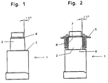
- FIG. 1 shows a pole shaft shaped according to the invention.
- FIG. 2 shows a pole feedthrough according to the invention.
- a pole shaft 1 is tapered from bottom to top by gradually reducing its diameter.
- the section 2 between the pole shoulders 3 and 4 which extends through the cover after installation in the cell has a slight conical deviation from the cylindrical shape which is approximately 1.5 °.
- the inner tube has a U-shaped double-edge profile, the gap of which is open at the top and can be filled with the same elastomer as that of the sealing plastic lining 7 and in the same spraying cycle.
- the inner tube clings to the pole shaft with a certain spring elasticity.
Landscapes
- Chemical & Material Sciences (AREA)
- Chemical Kinetics & Catalysis (AREA)
- Electrochemistry (AREA)
- General Chemical & Material Sciences (AREA)
- Sealing Battery Cases Or Jackets (AREA)
- Connection Of Batteries Or Terminals (AREA)
- Filling, Topping-Up Batteries (AREA)
- Fuel Cell (AREA)
Claims (3)
- Traversée de borne pour une cellule d'accumulateur électrique, notamment un accumulateur au plomb dont le couvercle de boîtier (5) en matière synthétique présente une ouverture de remplissage d'électrolyte ainsi que des ouvertures en forme de tube (6) présentant un revêtement en matière synthétique (7) réalisé par injection pour le passage étanche d'une tige de pôle (1), la matière synthétique du revêtement étant plus souple que le matériau du boîtier, caractérisée en ce que la surface de l'ouverture en forme de tube et au mois le tronçon (2) situé dans la zone de passage de la tige de pôle sont réalisés de façon légèrement conique, l'inclinaison de la surface d'étanchéité conique (8) définie par la surface de l'ouverture en forme de tube et la surface de pourtour opposée de la tige de pôle représentant environ 1,5° par rapport à la verticale.
- Traversée de borne selon la revendication 1, caractérisée en ce que le couvercle de boîtier est soudé à la caisse de boîtier.
- Traversée de borne selon la revendication 1, caractérisée en ce que le couvercle de boîtier est enfiché dans la caisse de boîtier.
Priority Applications (1)
| Application Number | Priority Date | Filing Date | Title |
|---|---|---|---|
| AT90124022T ATE93087T1 (de) | 1990-04-21 | 1990-12-13 | Poldurchfuehrung fuer eine elektrische akkumulatorenzelle. |
Applications Claiming Priority (2)
| Application Number | Priority Date | Filing Date | Title |
|---|---|---|---|
| DE9004533U | 1990-04-21 | ||
| DE9004533U DE9004533U1 (de) | 1990-04-21 | 1990-04-21 | Poldurchführung für eine elektrische Akkumulatorenzelle |
Publications (2)
| Publication Number | Publication Date |
|---|---|
| EP0453648A1 EP0453648A1 (fr) | 1991-10-30 |
| EP0453648B1 true EP0453648B1 (fr) | 1993-08-11 |
Family
ID=6853094
Family Applications (1)
| Application Number | Title | Priority Date | Filing Date |
|---|---|---|---|
| EP90124022A Expired - Lifetime EP0453648B1 (fr) | 1990-04-21 | 1990-12-13 | Traversée de borne pour une cellule d'accumulateur électrique |
Country Status (3)
| Country | Link |
|---|---|
| EP (1) | EP0453648B1 (fr) |
| AT (1) | ATE93087T1 (fr) |
| DE (2) | DE9004533U1 (fr) |
Families Citing this family (2)
| Publication number | Priority date | Publication date | Assignee | Title |
|---|---|---|---|---|
| DE9004533U1 (de) * | 1990-04-21 | 1990-06-28 | Varta Batterie Ag, 3000 Hannover | Poldurchführung für eine elektrische Akkumulatorenzelle |
| IT239433Y1 (it) * | 1995-12-28 | 2001-02-26 | Stocchiero Olimpio | Elemento tubolare di tenuta per poli di accumulatori elettrici |
Family Cites Families (10)
| Publication number | Priority date | Publication date | Assignee | Title |
|---|---|---|---|---|
| DE588219C (de) * | 1933-11-18 | Accumulatoren Fabrik Akt Ges | Dichtschliessender, abnehmbarer, ausschliesslich aus einer dicken Weichgummiplatte bestehender Deckel fuer die Gefaesse elektrischer Bleisammler | |
| US1376932A (en) * | 1919-12-05 | 1921-05-03 | Charles D Galloway | Storage battery |
| US1519867A (en) * | 1921-04-12 | 1924-12-16 | Paul M Marko | Storage-battery-cell cover |
| FR978323A (fr) * | 1948-12-30 | 1951-04-12 | Accumulateurs Slem | Perfectionnements apportés aux éléments d'accumulateurs |
| US2926210A (en) * | 1958-07-02 | 1960-02-23 | Norman D Sturges | Self-sealing battery terminal |
| DE1471760B2 (de) * | 1964-04-11 | 1969-10-09 | Robert Bosch Gmbh, 7000 Stuttgart | Verfahren zum Verbinden und Abdichten von Kasten und Deckel von Akkumulatoren mit saurem Elektrolyten |
| DE3722021A1 (de) * | 1987-07-03 | 1989-01-12 | Varta Batterie | Gehaeusedeckel aus kunststoff fuer akkumulatoren |
| DE8716389U1 (de) * | 1987-12-11 | 1988-02-11 | Varta Batterie Ag, 3000 Hannover | Poldurchführung |
| WO1990010954A1 (fr) * | 1989-03-10 | 1990-09-20 | Hardigg Industries, Inc. | Procede d'obturation entre une borne et un couvercle de batterie |
| DE9004533U1 (de) * | 1990-04-21 | 1990-06-28 | Varta Batterie Ag, 3000 Hannover | Poldurchführung für eine elektrische Akkumulatorenzelle |
-
1990
- 1990-04-21 DE DE9004533U patent/DE9004533U1/de not_active Expired - Lifetime
- 1990-12-13 AT AT90124022T patent/ATE93087T1/de active
- 1990-12-13 EP EP90124022A patent/EP0453648B1/fr not_active Expired - Lifetime
- 1990-12-13 DE DE9090124022T patent/DE59002333D1/de not_active Expired - Fee Related
Also Published As
| Publication number | Publication date |
|---|---|
| ATE93087T1 (de) | 1993-08-15 |
| DE9004533U1 (de) | 1990-06-28 |
| DE59002333D1 (de) | 1993-09-16 |
| EP0453648A1 (fr) | 1991-10-30 |
Similar Documents
| Publication | Publication Date | Title |
|---|---|---|
| DE2852889C2 (fr) | ||
| EP0601268B1 (fr) | Borne terminale pour accumulateur | |
| DE2757568A1 (de) | Elektrischer akkumulator | |
| DE2759000A1 (de) | Klappenventil | |
| EP3540885A1 (fr) | Boîte d'installation | |
| EP0426147B1 (fr) | Tuyau en béton ayant un revêtement interne anticorrosif à raccords de tuyau adaptés et dispositifs d'étanchéité intégrés dans les zones de raccordement | |
| EP1518308B1 (fr) | Passe-cable etanche aux fluides | |
| EP0453648B1 (fr) | Traversée de borne pour une cellule d'accumulateur électrique | |
| DE2932953A1 (de) | Rohranschluss | |
| EP0564896A1 (fr) | Traversée de borne pour cellules d'accumulateurs | |
| DE4127956B4 (de) | Anschlußpol für einen Akkumulator | |
| EP0346587A2 (fr) | Traversée de câble | |
| DE9209986U1 (de) | Bleiakkumulator | |
| DE3807840C1 (en) | Bushing for lines, such as cables or tubes, through a wall opening | |
| EP0319741B1 (fr) | Traversée de borne | |
| EP0073748A1 (fr) | Manchon de câble fendu longitudinalement à l'épreuve de la pression | |
| DE3111551A1 (de) | Anschlussklemmenanordnung an einer batterieseitenwand und verfahren zu deren herstellung | |
| DE10060110A1 (de) | Muffenisolierkörper mit Schraubverbinder zur Herstellung einer Kabelverbindung für Mittelspannungs-Kunststoffkabel | |
| DE20103785U1 (de) | Dichtungsmanschette | |
| EP0283729B1 (fr) | Raccord de tuyau pour tuyaux en matière plastique, consistant en matière thermoplastique, en particulier tubes pour câbles et tuyaux à haute pression | |
| DE3201324A1 (de) | Kabeleinfuehrungstuelle | |
| DE102016102490A1 (de) | Elektrische Kabelbaugruppe | |
| DE3021719A1 (de) | Anschlusskasten mit kabelstutzen fuer elektrische maschinen | |
| DE3328033C2 (de) | Hochspannungsstecker für eine Bildröhre | |
| DE2850195C2 (de) | Elektrischer Isolator |
Legal Events
| Date | Code | Title | Description |
|---|---|---|---|
| PUAI | Public reference made under article 153(3) epc to a published international application that has entered the european phase |
Free format text: ORIGINAL CODE: 0009012 |
|
| AK | Designated contracting states |
Kind code of ref document: A1 Designated state(s): AT BE DE ES FR GB IT NL SE |
|
| 17P | Request for examination filed |
Effective date: 19911128 |
|
| 17Q | First examination report despatched |
Effective date: 19920811 |
|
| GRAA | (expected) grant |
Free format text: ORIGINAL CODE: 0009210 |
|
| AK | Designated contracting states |
Kind code of ref document: B1 Designated state(s): AT BE DE ES FR GB IT NL SE |
|
| PG25 | Lapsed in a contracting state [announced via postgrant information from national office to epo] |
Ref country code: IT Free format text: LAPSE BECAUSE OF FAILURE TO SUBMIT A TRANSLATION OF THE DESCRIPTION OR TO PAY THE FEE WITHIN THE PRE;WARNING: LAPSES OF ITALIAN PATENTS WITH EFFECTIVE DATE BEFORE 2007 MAY HAVE OCCURRED AT ANY TIME BEFORE 2007. THE CORRECT EFFECTIVE DATE MAY BE DIFFERENT FROM THE ONE RECORDED.SCRIBED TIME-LIMIT Effective date: 19930811 Ref country code: BE Effective date: 19930811 Ref country code: NL Effective date: 19930811 Ref country code: ES Free format text: THE PATENT HAS BEEN ANNULLED BY A DECISION OF A NATIONAL AUTHORITY Effective date: 19930811 Ref country code: SE Effective date: 19930811 |
|
| REF | Corresponds to: |
Ref document number: 93087 Country of ref document: AT Date of ref document: 19930815 Kind code of ref document: T |
|
| GBT | Gb: translation of ep patent filed (gb section 77(6)(a)/1977) |
Effective date: 19930816 |
|
| REF | Corresponds to: |
Ref document number: 59002333 Country of ref document: DE Date of ref document: 19930916 |
|
| ET | Fr: translation filed | ||
| PG25 | Lapsed in a contracting state [announced via postgrant information from national office to epo] |
Ref country code: AT Effective date: 19931213 |
|
| NLV1 | Nl: lapsed or annulled due to failure to fulfill the requirements of art. 29p and 29m of the patents act | ||
| PLBE | No opposition filed within time limit |
Free format text: ORIGINAL CODE: 0009261 |
|
| STAA | Information on the status of an ep patent application or granted ep patent |
Free format text: STATUS: NO OPPOSITION FILED WITHIN TIME LIMIT |
|
| 26N | No opposition filed | ||
| PGFP | Annual fee paid to national office [announced via postgrant information from national office to epo] |
Ref country code: FR Payment date: 19941129 Year of fee payment: 5 |
|
| PGFP | Annual fee paid to national office [announced via postgrant information from national office to epo] |
Ref country code: GB Payment date: 19941205 Year of fee payment: 5 |
|
| PGFP | Annual fee paid to national office [announced via postgrant information from national office to epo] |
Ref country code: DE Payment date: 19951129 Year of fee payment: 6 |
|
| PG25 | Lapsed in a contracting state [announced via postgrant information from national office to epo] |
Ref country code: GB Effective date: 19951213 |
|
| GBPC | Gb: european patent ceased through non-payment of renewal fee |
Effective date: 19951213 |
|
| PG25 | Lapsed in a contracting state [announced via postgrant information from national office to epo] |
Ref country code: FR Effective date: 19960830 |
|
| REG | Reference to a national code |
Ref country code: FR Ref legal event code: ST |
|
| PG25 | Lapsed in a contracting state [announced via postgrant information from national office to epo] |
Ref country code: DE Effective date: 19970902 |