EP0453698A1 - Méthode de soudage au laser et un appareil pour localiser et serrer les pièces devant être soudées par cette méthode - Google Patents
Méthode de soudage au laser et un appareil pour localiser et serrer les pièces devant être soudées par cette méthode Download PDFInfo
- Publication number
- EP0453698A1 EP0453698A1 EP90830593A EP90830593A EP0453698A1 EP 0453698 A1 EP0453698 A1 EP 0453698A1 EP 90830593 A EP90830593 A EP 90830593A EP 90830593 A EP90830593 A EP 90830593A EP 0453698 A1 EP0453698 A1 EP 0453698A1
- Authority
- EP
- European Patent Office
- Prior art keywords
- welded
- parts
- welding line
- optical head
- clamping
- Prior art date
- Legal status (The legal status is an assumption and is not a legal conclusion. Google has not performed a legal analysis and makes no representation as to the accuracy of the status listed.)
- Withdrawn
Links
Images

Classifications
-
- B—PERFORMING OPERATIONS; TRANSPORTING
- B23—MACHINE TOOLS; METAL-WORKING NOT OTHERWISE PROVIDED FOR
- B23K—SOLDERING OR UNSOLDERING; WELDING; CLADDING OR PLATING BY SOLDERING OR WELDING; CUTTING BY APPLYING HEAT LOCALLY, e.g. FLAME CUTTING; WORKING BY LASER BEAM
- B23K26/00—Working by laser beam, e.g. welding, cutting or boring
- B23K26/02—Positioning or observing the workpiece, e.g. with respect to the point of impact; Aligning, aiming or focusing the laser beam
- B23K26/06—Shaping the laser beam, e.g. by masks or multi-focusing
- B23K26/067—Dividing the beam into multiple beams, e.g. multi-focusing
-
- B—PERFORMING OPERATIONS; TRANSPORTING
- B23—MACHINE TOOLS; METAL-WORKING NOT OTHERWISE PROVIDED FOR
- B23K—SOLDERING OR UNSOLDERING; WELDING; CLADDING OR PLATING BY SOLDERING OR WELDING; CUTTING BY APPLYING HEAT LOCALLY, e.g. FLAME CUTTING; WORKING BY LASER BEAM
- B23K26/00—Working by laser beam, e.g. welding, cutting or boring
- B23K26/02—Positioning or observing the workpiece, e.g. with respect to the point of impact; Aligning, aiming or focusing the laser beam
- B23K26/06—Shaping the laser beam, e.g. by masks or multi-focusing
-
- B—PERFORMING OPERATIONS; TRANSPORTING
- B23—MACHINE TOOLS; METAL-WORKING NOT OTHERWISE PROVIDED FOR
- B23K—SOLDERING OR UNSOLDERING; WELDING; CLADDING OR PLATING BY SOLDERING OR WELDING; CUTTING BY APPLYING HEAT LOCALLY, e.g. FLAME CUTTING; WORKING BY LASER BEAM
- B23K26/00—Working by laser beam, e.g. welding, cutting or boring
- B23K26/20—Bonding
- B23K26/21—Bonding by welding
- B23K26/24—Seam welding
- B23K26/244—Overlap seam welding
-
- B—PERFORMING OPERATIONS; TRANSPORTING
- B23—MACHINE TOOLS; METAL-WORKING NOT OTHERWISE PROVIDED FOR
- B23K—SOLDERING OR UNSOLDERING; WELDING; CLADDING OR PLATING BY SOLDERING OR WELDING; CUTTING BY APPLYING HEAT LOCALLY, e.g. FLAME CUTTING; WORKING BY LASER BEAM
- B23K26/00—Working by laser beam, e.g. welding, cutting or boring
- B23K26/20—Bonding
- B23K26/21—Bonding by welding
- B23K26/24—Seam welding
- B23K26/26—Seam welding of rectilinear seams
-
- B—PERFORMING OPERATIONS; TRANSPORTING
- B25—HAND TOOLS; PORTABLE POWER-DRIVEN TOOLS; MANIPULATORS
- B25B—TOOLS OR BENCH DEVICES NOT OTHERWISE PROVIDED FOR, FOR FASTENING, CONNECTING, DISENGAGING OR HOLDING
- B25B5/00—Clamps
- B25B5/16—Details, e.g. jaws, jaw attachments
Definitions
- the present invention relates to a method of forming a laser weld along a discontinuous welding line.
- a system for the multiple spot-welding of motor-vehicle bodywork elements is known from French patent application No. 2,549,759, in which the parts to be welded are clamped together by a plurality of clamps with holes which open in the gripping surfaces of the clamps.
- An optical head fixed to the respective clamp is arranged in each hole.
- Each optical head receives a laser beam from a source and focuses it onto the parts to be welded through the holes in the clamps.
- the main disadvantage of a system of this type is the fact that it is necessary to provide an optical head in correspondence with each welding point. This means that the system is quite complicated, particularly as regards the optical path from the laser source to each focusing head.
- the flexibility of a system of this type that is, its ability to operate on parts of different types, is very limited, precisely because of the focusing heads associated with each welding point.
- the clamps 3 may be formed with holes through which the laser beam is focused onto the parts to be welded.
- a subject of the present invention is a method of forming a laser weld along a discontinuous welding line by means of a welding device comprising means for emitting continuous laser radiation, an optical head for focusing a laser beam from the emission means onto the parts to be welded, and means for moving the optical head relative to the parts to be welded along a predetermined working path which corresponds to the welding line, the method being characterised in that it includes the step of providing a screen which is fixed relative to the parts to be welded and extends along the welding line between the optical head and the parts to be welded, the screen having a plurality of holes arranged in correspondence with the portions of the welding line in which the parts are to be welded.
- the method according to the invention produces a discontinuous weld whilst the source is operated continuously, without the need for a complex and expensive interception mechanism.
- the present invention results from the observation that the screen interposed between the optical head and the parts to be welded is struck by an unfocused beam which disperses its energy over a fairly large area and hence cannot significantly damage the screen.
- a subject of the present invention is apparatus for locating and clamping parts which are to be welded together by means of a laser welding device comprising means for emitting continuous laser radiation, an optical head for focusing a laser beam from the emission means onto the parts to be welded, and means for moving the optical head relative to the parts to be welded along a predetermined working path corresponding to a welding line, the apparatus including clamping means for clamping together the parts to be welded and intended to act on surface portions of one of the parts to be welded which are situated on the welding line, the apparatus being characterised in that it includes screening means which are fixed relative to the parts to be welded and extend along the welding line between the clamping means and the optical focusing head, the screening means having a plurality of holes arranged in correspondence with portions of the welding line where the clamping means do not act.
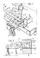
- Figure 1 shows a laser welding station including apparatus 12 for locating and clamping the parts to be welded, indicated 14 and 16 in the drawings.
- the part 14 is constituted by a pressed metal sheet, whilst the parts 16 for fixing to the sheet 14 are shaped stiffening and fixing flanges for the sheet 14.
- the clamping apparatus 12 comprises a plurality of clamping members 20 articulated to a fixed support structure (not shown) about an axis 22 (see also Figures 2 and 3).
- the clamping members 20 are constituted by spaced-apart rocker arms which are operable independently by means of actuators 24.
- Each clamping member 20 has an active portion 26 which acts on the surface of one of the parts to be welded (in the case under consideration on the part 16) and pushes the parts 14, 16 against a fixed abutment 28.
- the parts 14, 16 are to be welded together along portions 30 between two adjacent clamping members 20.
- an optical focusing head forms part of a laser welding device of known type.
- the welding device includes a source (not shown) which generates a laser beam which is transmitted by an optical chain to the head 32.
- the optical head 32 is controlled by a control unit, also of conventional type, and can be moved relative to the apparatus 12 along a predetermined working path.
- a screen 34 with a plurality of holes 36 arranged in correspondence with the portions 30 between adjacent clamping members 20 is interposed between the clamping members 20 and the optical head 32.
- the screen 34 is fixed relative to the base structure and is supported thereby in any known manner.
- the screen may be composed of a plurality of separate sections fixed to the surfaces of the clamping members 20 which face the optical head 32.
- the optical head 32 is supplied with a continuous laser beam and is moved in the direction indicated by the arrows A in Figures 1 and 2, along a working path which corresponds to a welding line on the surface of the part 16.
- the laser beam from the optical head 32 reaches the surface of the part 16 and welds the parts 14, 16 along the portions 30 between the clamping members 20.
- the laser beam is intercepted by the screen 34.
- the beam is not focused on the surface of the screen 34 since the screen is spaced from its focal point.
- the surface of the screen 34 is therefore not damaged significantly by the laser beam. Tests carried out by the Applicant have shown that a screen of normal carbon steel placed a few centimeters from the surface on which the laser beam is focused can withstand the incidence of a beam with a power of 1500-2000 KW.
- the screen is formed directly by the surfaces of the clamping members 20 which face the optical head 32.
- the gripping surfaces 40 of the clamping members 20 are shorter in the direction of the welding line than their screening surfaces 42. This prevents the edges 44 of the clamping members 20 from being welded to the part 16.
Landscapes
- Physics & Mathematics (AREA)
- Optics & Photonics (AREA)
- Engineering & Computer Science (AREA)
- Mechanical Engineering (AREA)
- Plasma & Fusion (AREA)
- Laser Beam Processing (AREA)
- Lining Or Joining Of Plastics Or The Like (AREA)
Applications Claiming Priority (2)
| Application Number | Priority Date | Filing Date | Title |
|---|---|---|---|
| IT6728390 | 1990-04-13 | ||
| IT67283A IT1240195B (it) | 1990-04-13 | 1990-04-13 | Procedimento per la saldatura laser ed attrezzatura per posizionare e bloccare pezzi destinati ad essere saldati mediante tale procedimento |
Publications (1)
| Publication Number | Publication Date |
|---|---|
| EP0453698A1 true EP0453698A1 (fr) | 1991-10-30 |
Family
ID=11301130
Family Applications (1)
| Application Number | Title | Priority Date | Filing Date |
|---|---|---|---|
| EP90830593A Withdrawn EP0453698A1 (fr) | 1990-04-13 | 1990-12-18 | Méthode de soudage au laser et un appareil pour localiser et serrer les pièces devant être soudées par cette méthode |
Country Status (3)
| Country | Link |
|---|---|
| EP (1) | EP0453698A1 (fr) |
| JP (1) | JPH0639576A (fr) |
| IT (1) | IT1240195B (fr) |
Cited By (11)
| Publication number | Priority date | Publication date | Assignee | Title |
|---|---|---|---|---|
| EP0609634A1 (fr) * | 1993-02-04 | 1994-08-10 | Megamation Incorporated | Porte-outil entraîné par des moteurs linéaires |
| EP1060837A3 (fr) * | 1999-05-28 | 2001-11-14 | BIELOMATIK LEUZE GmbH + Co. | Dispositif de serrage pour pièces, spécialement pour le soudage par laser de pièces synthétiques |
| WO2009077064A1 (fr) * | 2007-12-14 | 2009-06-25 | Thyssenkrupp Drauz Nothelfer Gmbh | Procédé et dispositif pour assembler des tôles sur leurs bords en utilisant un dispositif de raccordement pour l'optique laser |
| DE102008052489B4 (de) * | 2008-10-21 | 2012-04-05 | Ibs Filtran Kunststoff-/ Metallerzeugnisse Gmbh | Vorrichtung zum Verschweißen zweier Schweißartikel und Verfahren zum Betreiben der Vorrichtung |
| WO2013120606A1 (fr) * | 2012-02-16 | 2013-08-22 | Trumpf Werkzeugmaschinen Gmbh + Co. Kg | Dispositif d'usinage au laser ayant une tête d'usinage au laser mobile par rapport à une griffe de serrage |
| WO2014083617A1 (fr) * | 2012-11-27 | 2014-06-05 | トヨタ自動車株式会社 | Structure soudée par laser et procédé de soudage par laser |
| US20140333095A1 (en) * | 2009-04-03 | 2014-11-13 | GM Global Technology Operations LLC | Method for producing a body part of a vehicle and body part of a vehicle |
| CN107877014A (zh) * | 2017-11-20 | 2018-04-06 | 张家港初恒激光科技有限公司 | 一种可调节的同轴激光器焊线夹具装置 |
| CN111037160A (zh) * | 2019-11-28 | 2020-04-21 | 广东利元亨智能装备股份有限公司 | 焊接设备 |
| CN112935680A (zh) * | 2021-03-30 | 2021-06-11 | 安徽江淮汽车集团股份有限公司 | 焊接定位装置 |
| CN118371865A (zh) * | 2023-03-30 | 2024-07-23 | 山东亿福金业珠宝首饰有限公司 | 一种鱼钩扣点焊机 |
Families Citing this family (3)
| Publication number | Priority date | Publication date | Assignee | Title |
|---|---|---|---|---|
| EP1343410B1 (fr) | 2000-12-20 | 2011-01-26 | Showa Denko K.K. | Fibre de carbone ramifi e tir e la vapeur, composition transparente lectro-conductrice, et leurs utilisations |
| JP6970536B2 (ja) * | 2017-06-30 | 2021-11-24 | ダイセルポリマー株式会社 | 粗面化処理用治具 |
| FR3145105B1 (fr) * | 2023-01-24 | 2025-11-14 | Safran Aircraft Engines | Procede de soudage laser |
Citations (4)
| Publication number | Priority date | Publication date | Assignee | Title |
|---|---|---|---|---|
| US4379219A (en) * | 1980-04-21 | 1983-04-05 | The Gillette Company | Shaving unit and method of manufacture therefor |
| FR2549759A1 (fr) * | 1983-07-27 | 1985-02-01 | Sciaky Sa | Installation de soudage a points multiples, notamment pour carrosserie de vehicule |
| DE3717960A1 (de) * | 1987-05-27 | 1988-12-08 | Messer Griesheim Gmbh | Vorrichtung fuer das schweissen mit einem einen laserstrahl aussendenden laser |
| US4847467A (en) * | 1988-08-19 | 1989-07-11 | Colt 7 Inc. | Laser welding clamp |
-
1990
- 1990-04-13 IT IT67283A patent/IT1240195B/it active IP Right Grant
- 1990-12-18 EP EP90830593A patent/EP0453698A1/fr not_active Withdrawn
-
1991
- 1991-01-28 JP JP3025171A patent/JPH0639576A/ja active Pending
Patent Citations (4)
| Publication number | Priority date | Publication date | Assignee | Title |
|---|---|---|---|---|
| US4379219A (en) * | 1980-04-21 | 1983-04-05 | The Gillette Company | Shaving unit and method of manufacture therefor |
| FR2549759A1 (fr) * | 1983-07-27 | 1985-02-01 | Sciaky Sa | Installation de soudage a points multiples, notamment pour carrosserie de vehicule |
| DE3717960A1 (de) * | 1987-05-27 | 1988-12-08 | Messer Griesheim Gmbh | Vorrichtung fuer das schweissen mit einem einen laserstrahl aussendenden laser |
| US4847467A (en) * | 1988-08-19 | 1989-07-11 | Colt 7 Inc. | Laser welding clamp |
Cited By (19)
| Publication number | Priority date | Publication date | Assignee | Title |
|---|---|---|---|---|
| EP0609634A1 (fr) * | 1993-02-04 | 1994-08-10 | Megamation Incorporated | Porte-outil entraîné par des moteurs linéaires |
| EP1060837A3 (fr) * | 1999-05-28 | 2001-11-14 | BIELOMATIK LEUZE GmbH + Co. | Dispositif de serrage pour pièces, spécialement pour le soudage par laser de pièces synthétiques |
| WO2009077064A1 (fr) * | 2007-12-14 | 2009-06-25 | Thyssenkrupp Drauz Nothelfer Gmbh | Procédé et dispositif pour assembler des tôles sur leurs bords en utilisant un dispositif de raccordement pour l'optique laser |
| DE102008052489B4 (de) * | 2008-10-21 | 2012-04-05 | Ibs Filtran Kunststoff-/ Metallerzeugnisse Gmbh | Vorrichtung zum Verschweißen zweier Schweißartikel und Verfahren zum Betreiben der Vorrichtung |
| US20140333095A1 (en) * | 2009-04-03 | 2014-11-13 | GM Global Technology Operations LLC | Method for producing a body part of a vehicle and body part of a vehicle |
| US9731382B2 (en) * | 2009-04-03 | 2017-08-15 | GM Global Technology Operations LLC | Method for producing a body part of a vehicle and body part of a vehicle |
| US9744622B2 (en) | 2012-02-16 | 2017-08-29 | Trumpf Laser Gmbh | Moving a laser processing head relative to a clamping claw |
| CN104379297A (zh) * | 2012-02-16 | 2015-02-25 | 通快激光有限责任公司 | 具有相对于夹爪可运动的激光加工头的激光加工设备 |
| CN104379297B (zh) * | 2012-02-16 | 2016-12-07 | 通快激光有限责任公司 | 具有相对于夹爪可运动的激光加工头的激光加工设备 |
| WO2013120606A1 (fr) * | 2012-02-16 | 2013-08-22 | Trumpf Werkzeugmaschinen Gmbh + Co. Kg | Dispositif d'usinage au laser ayant une tête d'usinage au laser mobile par rapport à une griffe de serrage |
| EP2926938A4 (fr) * | 2012-11-27 | 2016-02-24 | Toyota Motor Co Ltd | Structure soudée par laser et procédé de soudage par laser |
| US9713857B2 (en) | 2012-11-27 | 2017-07-25 | Toyota Jidosha Kabushiki Kaisha | Laser joining structure and laser joining method |
| WO2014083617A1 (fr) * | 2012-11-27 | 2014-06-05 | トヨタ自動車株式会社 | Structure soudée par laser et procédé de soudage par laser |
| CN107877014A (zh) * | 2017-11-20 | 2018-04-06 | 张家港初恒激光科技有限公司 | 一种可调节的同轴激光器焊线夹具装置 |
| CN107877014B (zh) * | 2017-11-20 | 2019-11-15 | 张家港初恒激光科技有限公司 | 一种可调节的同轴激光器焊线夹具装置 |
| CN111037160A (zh) * | 2019-11-28 | 2020-04-21 | 广东利元亨智能装备股份有限公司 | 焊接设备 |
| CN112935680A (zh) * | 2021-03-30 | 2021-06-11 | 安徽江淮汽车集团股份有限公司 | 焊接定位装置 |
| CN112935680B (zh) * | 2021-03-30 | 2022-08-02 | 安徽江淮汽车集团股份有限公司 | 焊接定位装置 |
| CN118371865A (zh) * | 2023-03-30 | 2024-07-23 | 山东亿福金业珠宝首饰有限公司 | 一种鱼钩扣点焊机 |
Also Published As
| Publication number | Publication date |
|---|---|
| IT1240195B (it) | 1993-11-27 |
| JPH0639576A (ja) | 1994-02-15 |
| IT9067283A1 (it) | 1991-10-13 |
| IT9067283A0 (it) | 1990-04-13 |
Similar Documents
| Publication | Publication Date | Title |
|---|---|---|
| EP0453698A1 (fr) | Méthode de soudage au laser et un appareil pour localiser et serrer les pièces devant être soudées par cette méthode | |
| JP2588638B2 (ja) | 自動車用車体の溶接装置 | |
| US6191383B1 (en) | Welding device | |
| US5478983A (en) | Process and apparatus for welding or heat treating by laser | |
| US4572941A (en) | Method of and installation for spot-welding by laser beam | |
| ZA924600B (en) | High production laser welding assembly and method | |
| ES8507028A1 (es) | Procedimiento e instalacion de soldadura de puntos por rayo laser. | |
| JPH0677841B2 (ja) | シートメタルを溶接する方法 | |
| ES2100488T3 (es) | Procedimiento de soldadura borde con borde de por lo menos dos chapas. | |
| US7312417B2 (en) | Laser beam seam welding with prior laser spot welding | |
| JPH11226763A (ja) | レーザ溶接装置 | |
| JP2008213005A (ja) | レーザ溶接方法 | |
| FR2638993B1 (fr) | Dispositif de decapage de deux bords de tole metallique a souder | |
| JPH06304772A (ja) | レーザ溶接方法 | |
| US20250114866A1 (en) | Method of manufacturing welded member | |
| JPH0760473A (ja) | レーザー溶接法 | |
| JP2010279965A (ja) | レーザー溶接方法 | |
| JPH0866782A (ja) | 格子部材の接合方法および接合装置 | |
| JPH0429476B2 (fr) | ||
| JP2005095908A (ja) | レーザ溶接装置及びレーザ溶接方法 | |
| CA2543692A1 (fr) | Methode et dispositif de soudage par faisceau laser | |
| Berniolles | Process for assembling two sheet parts, metallic assembly and structure of the sheet armour obtained with this process |
Legal Events
| Date | Code | Title | Description |
|---|---|---|---|
| PUAI | Public reference made under article 153(3) epc to a published international application that has entered the european phase |
Free format text: ORIGINAL CODE: 0009012 |
|
| AK | Designated contracting states |
Kind code of ref document: A1 Designated state(s): BE CH DE ES FR GB IT LI NL SE |
|
| STAA | Information on the status of an ep patent application or granted ep patent |
Free format text: STATUS: THE APPLICATION IS DEEMED TO BE WITHDRAWN |
|
| 18D | Application deemed to be withdrawn |
Effective date: 19920503 |