EP0453725B1 - Barre conductrice transparente - Google Patents
Barre conductrice transparente Download PDFInfo
- Publication number
- EP0453725B1 EP0453725B1 EP91102525A EP91102525A EP0453725B1 EP 0453725 B1 EP0453725 B1 EP 0453725B1 EP 91102525 A EP91102525 A EP 91102525A EP 91102525 A EP91102525 A EP 91102525A EP 0453725 B1 EP0453725 B1 EP 0453725B1
- Authority
- EP
- European Patent Office
- Prior art keywords
- conductor rail
- rail according
- current conductors
- carrier body
- glass
- Prior art date
- Legal status (The legal status is an assumption and is not a legal conclusion. Google has not performed a legal analysis and makes no representation as to the accuracy of the status listed.)
- Expired - Lifetime
Links
- 239000004020 conductor Substances 0.000 claims abstract description 22
- 239000011521 glass Substances 0.000 claims abstract description 14
- 229920003023 plastic Polymers 0.000 claims description 4
- 239000000853 adhesive Substances 0.000 claims 1
- 230000001070 adhesive effect Effects 0.000 claims 1
- 239000011888 foil Substances 0.000 claims 1
- 239000005368 silicate glass Substances 0.000 claims 1
- 239000002313 adhesive film Substances 0.000 description 3
- 239000010410 layer Substances 0.000 description 3
- 239000000463 material Substances 0.000 description 3
- 230000003287 optical effect Effects 0.000 description 3
- 239000007787 solid Substances 0.000 description 2
- 239000012790 adhesive layer Substances 0.000 description 1
- 239000002390 adhesive tape Substances 0.000 description 1
- 239000003365 glass fiber Substances 0.000 description 1
- 230000002787 reinforcement Effects 0.000 description 1
- IHQKEDIOMGYHEB-UHFFFAOYSA-M sodium dimethylarsinate Chemical class [Na+].C[As](C)([O-])=O IHQKEDIOMGYHEB-UHFFFAOYSA-M 0.000 description 1
Images

Classifications
-
- H—ELECTRICITY
- H01—ELECTRIC ELEMENTS
- H01R—ELECTRICALLY-CONDUCTIVE CONNECTIONS; STRUCTURAL ASSOCIATIONS OF A PLURALITY OF MUTUALLY-INSULATED ELECTRICAL CONNECTING ELEMENTS; COUPLING DEVICES; CURRENT COLLECTORS
- H01R25/00—Coupling parts adapted for simultaneous co-operation with two or more identical counterparts, e.g. for distributing energy to two or more circuits
- H01R25/14—Rails or bus-bars constructed so that the counterparts can be connected thereto at any point along their length
- H01R25/147—Low voltage devices, i.e. safe to touch live conductors
Definitions
- the invention relates to a busbar according to the preamble of claim 1.
- busbar In a known busbar of this type (DE-U-8715494), the busbar is round and made of transparent plastic material.
- Busbars made of transparent plastic material have not become established in practice. Their stiffness and stability is too low. In addition, the optical properties of such transparent plastic rails are inadequate. If the stability is increased by reinforcement with glass fibers or other inserts, the optical properties of such a busbar are no longer satisfactory.
- the invention has for its object to design a busbar of the type presumed to be known so that it is comparatively stable on the one hand and on the other hand has excellent optical properties.
- the carrier body consists of glass.
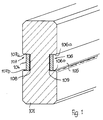
- a solid support body 101 made of glass is provided.
- the carrier body 101 has a rectangular cross section with chamfered corners.
- longitudinal grooves 106 and 107 are provided in the middle of both broad sides.
- Suitable current conductors 104 and 105 are inserted in the longitudinal grooves in their width.
- the current conductors 104 and 105 are bonded to the glass body 101 on the base of the longitudinal grooves 106 and 107 via transparent adhesive layers 108 and 109, which could be formed, for example, by double-acting, transparent adhesive tape.
- the reference numerals of the second exemplary embodiment are chosen such that they correspond to those of the first exemplary embodiment as far as possible, but are reduced by an amount of 100.
- a middle layer 1 consisting of glass is provided.
- Two double-sided transparent adhesive films 8 and 9 are applied to this middle layer 1 made of glass.
- the adhesive films 8 and 9 carry the divided outer layers 2a and 2b or 3a and 3b.
- the current conductors 4 and 5 are glued to the double-sided adhesive films 8 and 9 and are located in the longitudinal grooves 6 and 7, which have side flanks 6a, 6b, 7a and 7b converging towards the outside.
Landscapes
- Joining Of Glass To Other Materials (AREA)
- Connections Effected By Soldering, Adhesion, Or Permanent Deformation (AREA)
- Non-Insulated Conductors (AREA)
- Insulated Conductors (AREA)
- Electrochromic Elements, Electrophoresis, Or Variable Reflection Or Absorption Elements (AREA)
- Liquid Crystal (AREA)
- Devices For Indicating Variable Information By Combining Individual Elements (AREA)
- Glass Compositions (AREA)
- Non-Silver Salt Photosensitive Materials And Non-Silver Salt Photography (AREA)
Claims (10)
- Barre conductrice avec deux conducteurs disposés de différents côtés, saisissables de l'extérieur et fixés sur un corps porteur isolant, transparent,
caractérisée en ce que
le corps porteur (101; 1, 2a, 2b, 3a, 3b) est en verre. - Barre conductrice selon la revendication 1,
caractérisée en ce que
le corps porteur (101; 1, 2a, 2b, 3a, 3b) présente une section transversale rectangulaire et que les conducteurs (104; 105; 4; 5) sont disposés sur les deux côtés larges. - Barre conductrice selon la revendication 1 ou 2,
caractérisée en ce que
le verre du corps porteur est du verre de silicate. - Barre conductrice selon l'une ou plusieurs des revendications 1 à 3,
caractérisée en ce que
le corps porteur (1, 2a, 2b, 3a, 3b) est composé de plusieurs couches de verre, comprenant une couche centrale (1), sur les différents côtés de laquelle deux couches extérieures (2a, 2b; 3a, 3b) sont collées, les couches extérieure (2a, 2b; 3a, 3b) étant divisée dans le sens longitudinal en formant chacune une rainure longitudinale (6; 7), et que les conducteurs (5; 4) sont collés à l'intérieur des rainures longitudinales (6; 7). - Barre conductrice selon la revendication 4,
caractérisée en ce que
les conducteurs (4; 5) sont collés sur la couche centrale (1). - Barre conductrice selon l'une ou plusieurs des revendications 1 à 5,
caractérisée en ce que
une feuille en matière plastique transparente (8; 9), collant des deux côtés, est prévue sur chacun des côtés de la couche centrale (1) et fixe aussi bien les couches extérieures (3a, 3b; 2a, 2b) que les conducteurs (4; 5) sur la couche centrale (1). - Barre conductrice selon l'une ou plusieurs des revendications 1 à 6,
caractérisée en ce que
les rainures longitudinales (6; 7) de la couche centrale (1) présentent des flancs (6, 6b; 7, 7b) qui convergent, l'un vers l'autre, vers l'extérieur. - Barre conductrice selon l'une ou plusieurs des revendications 1 à 7,
caractérisée en ce que
les surfaces de contact (104a; 105a; 4a; 5a) des conducteurs (104; 105; 4; 5) sont en retrait par rapport au contour extérieur voisin du corps porteur. - Barre conductrice selon l'une ou plusieurs des revendications 1 à 8,
caractérisée en ce que
les conducteurs (104; 105; 4; 5) sont rectangulaires et portent bien sous les flancs (107a, 107b; 106a, 106b; 7a, 7b; 6a, 6b) des rainures longitudinales (107; 106; 7; 6). - Barre conductrice selon l'une ou plusieurs des revendications 1 à 9,
caractérisée en ce que
les rainures longitudinales (107; 106) sont disposées, avec les conducteurs (104; 105), au centre des côtés larges.
Applications Claiming Priority (2)
| Application Number | Priority Date | Filing Date | Title |
|---|---|---|---|
| DE4013529A DE4013529A1 (de) | 1990-04-27 | 1990-04-27 | Transparente stromschiene |
| DE4013529 | 1990-04-27 |
Publications (3)
| Publication Number | Publication Date |
|---|---|
| EP0453725A2 EP0453725A2 (fr) | 1991-10-30 |
| EP0453725A3 EP0453725A3 (en) | 1991-12-18 |
| EP0453725B1 true EP0453725B1 (fr) | 1995-02-01 |
Family
ID=6405257
Family Applications (1)
| Application Number | Title | Priority Date | Filing Date |
|---|---|---|---|
| EP91102525A Expired - Lifetime EP0453725B1 (fr) | 1990-04-27 | 1991-02-21 | Barre conductrice transparente |
Country Status (5)
| Country | Link |
|---|---|
| US (1) | US5151037A (fr) |
| EP (1) | EP0453725B1 (fr) |
| AT (1) | ATE118122T1 (fr) |
| DE (2) | DE4013529A1 (fr) |
| ES (1) | ES2067065T3 (fr) |
Cited By (1)
| Publication number | Priority date | Publication date | Assignee | Title |
|---|---|---|---|---|
| DE19750100A1 (de) * | 1997-11-12 | 1999-06-10 | Zumtobel Staff Gmbh & Co Kg | Verbindungsvorrichtung |
Families Citing this family (17)
| Publication number | Priority date | Publication date | Assignee | Title |
|---|---|---|---|---|
| DE4239625C1 (en) * | 1992-11-26 | 1993-08-05 | Fresenius Ag, 6380 Bad Homburg, De | Medical transfusion equipment connecting column - forms connection with data exchange equipment and has two conductors secured by clamp with jaws and electrical contacts |
| US5340322A (en) * | 1993-04-22 | 1994-08-23 | Poulsen Peder Ulrik | Low voltage cable lighting system |
| US5890918A (en) * | 1994-12-01 | 1999-04-06 | Hierzer; Andreas | Low voltage current supply device |
| DE29514672U1 (de) * | 1995-09-13 | 1995-12-07 | LTS Licht & Leuchten GmbH, 88069 Tettnang | Stromleitersystem |
| US5833358A (en) * | 1995-11-21 | 1998-11-10 | Aci The Display People | Extruded track lighting system |
| USD399594S (en) | 1996-11-04 | 1998-10-13 | Aci The Display People | Extruded track lighting system |
| FR2805409B1 (fr) * | 2000-02-23 | 2002-06-28 | Labinal | Dispositif de distribution de puissance comportant des barres appliquees sur une platine |
| US6244733B1 (en) | 2000-02-25 | 2001-06-12 | Juno Manufacturing, Inc. | Low voltage track lighting system |
| GB2387146B (en) | 2002-03-27 | 2005-03-02 | Autoliv Dev | Improvements relating to an air bag |
| US7105744B1 (en) | 2003-03-18 | 2006-09-12 | Regal King Comercial Offshore De Macau Limitada | Mounting bracket for electrical fixtures |
| CN101005187B (zh) * | 2006-12-07 | 2010-10-13 | 广州电器科学研究院 | 一体化同相逆并联导排制造方法及其结构 |
| US7507005B1 (en) | 2007-01-30 | 2009-03-24 | Genlyte Thomas Group Llc | Sliding flexible track lighting |
| US7758358B1 (en) | 2008-05-05 | 2010-07-20 | Koninklijke Philips Electronics N.V. | Track lighting assembly |
| DE102009033465A1 (de) * | 2009-07-10 | 2011-01-13 | Siemens Aktiengesellschaft | Modulare Stromschiene |
| JP2013258044A (ja) * | 2012-06-12 | 2013-12-26 | Molex Inc | コネクタ |
| TW201712272A (zh) * | 2015-09-22 | 2017-04-01 | 隆達電子股份有限公司 | 連接桿及應用其之燈具 |
| US10177513B1 (en) * | 2017-12-28 | 2019-01-08 | Lear Corporation | Bus bar assembly with a system to form and secure connections to the terminals on a bus bar |
Family Cites Families (7)
| Publication number | Priority date | Publication date | Assignee | Title |
|---|---|---|---|---|
| GB764151A (en) * | 1954-02-08 | 1956-12-19 | Georg Peter Christian Nielsen | Improvements in or relating to toy vehicles provided with built-in motors and tracts therefor |
| US4941207A (en) * | 1984-05-01 | 1990-07-10 | Nihon Musen Kabushiki Kaisha | Structure for wireless communication in an electromagnetically shielded building |
| GB2185863B (en) * | 1986-01-28 | 1990-07-18 | Illuma Designs Limited | Tracked lighting systems |
| US4861273A (en) * | 1987-10-13 | 1989-08-29 | Thomas Industries, Inc. | Low-voltage miniature track lighting system |
| DE8715494U1 (de) * | 1987-11-23 | 1988-03-03 | Apel, Uwe, Dipl.-Ing., 2123 Bardowick | Niedervolt-Stromschienenvorrichtung für 2-Phasenbetrieb |
| DE3828418A1 (de) * | 1988-08-20 | 1990-02-22 | Mann Michael | Flexible leitungsanordnung zur stromversorgung von verbrauchern im niederspannungsbereich, insbesondere zur stromversorgung von halogenlampen |
| EP0360971A3 (fr) * | 1988-08-31 | 1991-07-17 | Mitsui Mining & Smelting Co., Ltd. | Substrat de montage et sa méthode de production et circuit imprimé ayant une fonction de connecteur et sa méthode de connexion |
-
1990
- 1990-04-27 DE DE4013529A patent/DE4013529A1/de not_active Withdrawn
-
1991
- 1991-02-21 EP EP91102525A patent/EP0453725B1/fr not_active Expired - Lifetime
- 1991-02-21 AT AT91102525T patent/ATE118122T1/de not_active IP Right Cessation
- 1991-02-21 ES ES91102525T patent/ES2067065T3/es not_active Expired - Lifetime
- 1991-02-21 DE DE59104452T patent/DE59104452D1/de not_active Expired - Lifetime
- 1991-04-26 US US07/691,847 patent/US5151037A/en not_active Expired - Lifetime
Cited By (2)
| Publication number | Priority date | Publication date | Assignee | Title |
|---|---|---|---|---|
| DE19750100A1 (de) * | 1997-11-12 | 1999-06-10 | Zumtobel Staff Gmbh & Co Kg | Verbindungsvorrichtung |
| DE19750100C2 (de) * | 1997-11-12 | 2003-04-10 | Zumtobel Staff Gmbh & Co Kg | Verbindungsvorrichtung |
Also Published As
| Publication number | Publication date |
|---|---|
| EP0453725A2 (fr) | 1991-10-30 |
| ES2067065T3 (es) | 1995-03-16 |
| ATE118122T1 (de) | 1995-02-15 |
| EP0453725A3 (en) | 1991-12-18 |
| US5151037A (en) | 1992-09-29 |
| DE59104452D1 (de) | 1995-03-16 |
| DE4013529A1 (de) | 1991-10-31 |
Similar Documents
| Publication | Publication Date | Title |
|---|---|---|
| EP0453725B1 (fr) | Barre conductrice transparente | |
| DE3012830C2 (fr) | ||
| DE2940339C2 (fr) | ||
| DE2557660A1 (de) | Verfahren und vorrichtung zum spleissen optischer fasern | |
| DE2449359A1 (de) | Koppelvorrichtung fuer optische fasern | |
| DE2901416A1 (de) | Anordnung zum elektrischen verbinden einer vielzahl von anschluessen | |
| DE2902089A1 (de) | Verbindungsmodul zum verbinden einadriger optischer leiter und damit ausgeruesteter verbinder | |
| DE10018680A1 (de) | Kontaktschienenanordnung | |
| DE2508825B1 (de) | Verseilelement fuer optische kabel | |
| EP2982016A1 (fr) | Dispositif de retenue modulaire pour conducteurs électriques | |
| DE1185730B (de) | Anordnung mit mindestens einem Esaki-Diodenpaar | |
| DE2902259C2 (de) | Bandförmiges Lichtleitelement | |
| DE3143555A1 (de) | Dachkonstruktion fuer ein fahrzeug | |
| DE2834525C2 (de) | Gedruckte Schaltung auf flexiblem Basismaterial mit von der Hauptschaltungsachse abzweigenden Auslegern zur intermodularen Verbindung eines Baugruppen aufweisenden Fernsehgerätechassis | |
| DE3931446A1 (de) | Kaefig fuer ein waelzlager fuer laengsbewegungen | |
| DE19912183A1 (de) | Längsgesickter Träger, insbesondere Dachträger für ein Kraftfahrzeug | |
| DE9004781U1 (de) | Transparente Stromschiene | |
| EP0174385B1 (fr) | Dispositif de support pour conducteurs électriques | |
| DE1690352C3 (de) | Sammelschienenanordnung | |
| DE821242C (de) | Mehrfachkondensator | |
| DE3143604A1 (de) | Transport- und magaziniereinrichtung fuer elektrotechnische bauelemente | |
| DE3211540A1 (de) | Miniaturisierte stromschiene hoher kapazitanz und verfahren zur herstellung derselben | |
| EP0254275A2 (fr) | Guides d'ondes lumineuses sous gaine plastique | |
| DE9420887U1 (de) | Positions- oder/und Weg-Aufnehmer | |
| AT391748B (de) | Extrudiertes kunststoffrohr |
Legal Events
| Date | Code | Title | Description |
|---|---|---|---|
| PUAI | Public reference made under article 153(3) epc to a published international application that has entered the european phase |
Free format text: ORIGINAL CODE: 0009012 |
|
| PUAL | Search report despatched |
Free format text: ORIGINAL CODE: 0009013 |
|
| AK | Designated contracting states |
Kind code of ref document: A2 Designated state(s): AT DE ES FR GB IT |
|
| AK | Designated contracting states |
Kind code of ref document: A3 Designated state(s): AT DE ES FR GB IT |
|
| 17P | Request for examination filed |
Effective date: 19911106 |
|
| 17Q | First examination report despatched |
Effective date: 19940331 |
|
| GRAA | (expected) grant |
Free format text: ORIGINAL CODE: 0009210 |
|
| AK | Designated contracting states |
Kind code of ref document: B1 Designated state(s): AT DE ES FR GB IT |
|
| REF | Corresponds to: |
Ref document number: 118122 Country of ref document: AT Date of ref document: 19950215 Kind code of ref document: T |
|
| GBT | Gb: translation of ep patent filed (gb section 77(6)(a)/1977) |
Effective date: 19950127 |
|
| ET | Fr: translation filed | ||
| REF | Corresponds to: |
Ref document number: 59104452 Country of ref document: DE Date of ref document: 19950316 |
|
| REG | Reference to a national code |
Ref country code: ES Ref legal event code: FG2A Ref document number: 2067065 Country of ref document: ES Kind code of ref document: T3 |
|
| ITF | It: translation for a ep patent filed | ||
| PLBE | No opposition filed within time limit |
Free format text: ORIGINAL CODE: 0009261 |
|
| STAA | Information on the status of an ep patent application or granted ep patent |
Free format text: STATUS: NO OPPOSITION FILED WITHIN TIME LIMIT |
|
| 26N | No opposition filed | ||
| REG | Reference to a national code |
Ref country code: GB Ref legal event code: IF02 |
|
| REG | Reference to a national code |
Ref country code: ES Ref legal event code: PC2A |
|
| PGFP | Annual fee paid to national office [announced via postgrant information from national office to epo] |
Ref country code: ES Payment date: 20100121 Year of fee payment: 20 |
|
| PGFP | Annual fee paid to national office [announced via postgrant information from national office to epo] |
Ref country code: IT Payment date: 20100225 Year of fee payment: 20 Ref country code: FR Payment date: 20100312 Year of fee payment: 20 |
|
| PGFP | Annual fee paid to national office [announced via postgrant information from national office to epo] |
Ref country code: DE Payment date: 20100104 Year of fee payment: 20 Ref country code: GB Payment date: 20100105 Year of fee payment: 20 Ref country code: AT Payment date: 20100225 Year of fee payment: 20 |
|
| REG | Reference to a national code |
Ref country code: DE Ref legal event code: R071 Ref document number: 59104452 Country of ref document: DE |
|
| REG | Reference to a national code |
Ref country code: GB Ref legal event code: PE20 Expiry date: 20110220 |
|
| PG25 | Lapsed in a contracting state [announced via postgrant information from national office to epo] |
Ref country code: GB Free format text: LAPSE BECAUSE OF EXPIRATION OF PROTECTION Effective date: 20110220 |
|
| PG25 | Lapsed in a contracting state [announced via postgrant information from national office to epo] |
Ref country code: DE Free format text: LAPSE BECAUSE OF EXPIRATION OF PROTECTION Effective date: 20110221 |
|
| REG | Reference to a national code |
Ref country code: ES Ref legal event code: FD2A Effective date: 20130723 |
|
| PG25 | Lapsed in a contracting state [announced via postgrant information from national office to epo] |
Ref country code: ES Free format text: LAPSE BECAUSE OF EXPIRATION OF PROTECTION Effective date: 20110222 |