EP0453843A2 - Dispositif de contrôle de pinces pour machines rotatives d'impression à feuilles - Google Patents
Dispositif de contrôle de pinces pour machines rotatives d'impression à feuilles Download PDFInfo
- Publication number
- EP0453843A2 EP0453843A2 EP91105473A EP91105473A EP0453843A2 EP 0453843 A2 EP0453843 A2 EP 0453843A2 EP 91105473 A EP91105473 A EP 91105473A EP 91105473 A EP91105473 A EP 91105473A EP 0453843 A2 EP0453843 A2 EP 0453843A2
- Authority
- EP
- European Patent Office
- Prior art keywords
- gripper
- cam
- roller
- bearing pin
- pin
- Prior art date
- Legal status (The legal status is an assumption and is not a legal conclusion. Google has not performed a legal analysis and makes no representation as to the accuracy of the status listed.)
- Granted
Links
Images
Classifications
-
- B—PERFORMING OPERATIONS; TRANSPORTING
- B41—PRINTING; LINING MACHINES; TYPEWRITERS; STAMPS
- B41F—PRINTING MACHINES OR PRESSES
- B41F21/00—Devices for conveying sheets through printing apparatus or machines
- B41F21/10—Combinations of transfer drums and grippers
Definitions
- the invention relates to a device for controlling grippers in sheet-fed rotary printing machines according to the preamble of the first claim.
- a disadvantage is that the cam rollers due to manufacturing and assembly errors in a sheet-guiding cylinder with two rows of grippers at the periphery not exactly o 180 envelope angle ⁇ from each other are removed, such as but at schtourigen cylinders, that such is required with two rows of grippers, necessarily .
- the consequence of this is that the grippers of one or both rows of grippers open too early or too late.
- Such errors in the geometry have a disadvantageous effect on a register-based transfer of printed sheets from one printing unit to the next one.
- the object of the invention is to further develop a device of the aforementioned type so that the peripheral position of the cam followers to each other exactly ⁇ to 180 o envelope angle is adjustable.
- the advantage of the invention is that the in-register transfer of the printed sheets from one printing unit to the next not faulty adjustment deviating from 180 ° of the cam rollers on the circumference of the double-sized sheet-conveying cylinder affects more is because the circumferential position of the cam rollers can be set exactly to each other at 180 o angle ⁇ (semicircle).
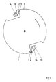
- arc-guiding cylinder 1 is shown, on which diametrically opposed gripper shafts 14 are provided, on which gripper fingers 2 are mounted by means of gripper holders 18.
- the gripper shaft 14 of the first row of grippers is rotatably mounted on the sheet-guiding cylinder 1, which is double-sized compared to the plate cylinder (not shown).
- the gripper consisting of gripper holder 18 and gripper finger 2 are arranged by means of gripper spring 19 with a non-positive connection.
- the grippers are generally known and are not the subject of the invention.
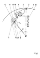
- the grippers are controlled by a cam drive 7, 8, 11, which consists of a fixed, e.g. consists of a piece of control cam 11, a cam roller 7 and a roller lever 8.
- a cam roller 7 is at least provided, whose center line 16 is displaceable to the axis of the gripper shaft 14 such that the axial distance changes.
- Each roller lever 8 is fixed on the associated gripper shaft 14.
- the contact of the cam rollers 7 with the control cam 11 is ensured by a compression spring 20 acting against the roller lever 8.
- the cam mechanism 7, 8, 11 enables the cam law of the control cam 11 to be directly transferred to the gripper fingers 2 of the two gripper rows.
- a cam roller 7 can be adjusted from its position T1 to the position T2.
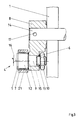
- a stepped bearing pin 5 with a coaxial section 9 is preferably accommodated in the bearing bore 6 of the roller lever 8 assigned to the cam roller 7.
- an eccentric pin 12 is provided, on which the cam roller 7 is rotated freely.
- a coaxial pin with a fine thread 13 is attached to the offset bearing pin 5, on which a locking nut 10 is provided.
- the offset bearing pin 5 can be rotated from the outside and the set position can be secured by means of the locking nut 10 by pressing the offset bearing pin 5 against the roller lever 8 by means of the locking nut 10.
- the center line 16 of the cam roller 7 moves around the center line 15 of the bearing bore 6 by ⁇ ⁇ from T2 to T1, as a result of which the change in the center distance of the cam roller 7, i.e. the center line 16 to the fixed pivot axis of the gripper shaft 14 is effected.
- the displacement of the cam roller 7 is not limited to the embodiment with the eccentric adjustment described, but can also be achieved by a displaceable mounting of a bearing pin 5 in the roller lever 8 and a corresponding setting option or, if necessary, also by eccentric or displaceable mounting of the roller lever 8 on the gripper shaft 14.
Landscapes
- Feeding Of Articles By Means Other Than Belts Or Rollers (AREA)
- Supply, Installation And Extraction Of Printed Sheets Or Plates (AREA)
- Discharge By Other Means (AREA)
- Holding Or Fastening Of Disk On Rotational Shaft (AREA)
- Labeling Devices (AREA)
- Advancing Webs (AREA)
- Inking, Control Or Cleaning Of Printing Machines (AREA)
Applications Claiming Priority (2)
| Application Number | Priority Date | Filing Date | Title |
|---|---|---|---|
| DE4013261A DE4013261C1 (fr) | 1990-04-26 | 1990-04-26 | |
| DE4013261 | 1990-04-26 |
Publications (3)
| Publication Number | Publication Date |
|---|---|
| EP0453843A2 true EP0453843A2 (fr) | 1991-10-30 |
| EP0453843A3 EP0453843A3 (en) | 1992-02-26 |
| EP0453843B1 EP0453843B1 (fr) | 1994-06-15 |
Family
ID=6405102
Family Applications (1)
| Application Number | Title | Priority Date | Filing Date |
|---|---|---|---|
| EP91105473A Expired - Lifetime EP0453843B1 (fr) | 1990-04-26 | 1991-04-06 | Dispositif de contrôle de pinces pour machines rotatives d'impression à feuilles |
Country Status (7)
| Country | Link |
|---|---|
| US (1) | US5110109A (fr) |
| EP (1) | EP0453843B1 (fr) |
| JP (1) | JP2566690B2 (fr) |
| AT (1) | ATE107228T1 (fr) |
| BR (1) | BR9101677A (fr) |
| DE (2) | DE4013261C1 (fr) |
| ES (1) | ES2055936T3 (fr) |
Families Citing this family (3)
| Publication number | Priority date | Publication date | Assignee | Title |
|---|---|---|---|---|
| JP4023629B2 (ja) * | 1996-02-19 | 2007-12-19 | カーベーアー−ジオリ ソシエテ アノニム | 枚葉紙印刷機用圧胴 |
| DE19618029B4 (de) * | 1996-05-04 | 2006-07-27 | Heidelberger Druckmaschinen Ag | Verfahren und Vorrichtung zur Beseitigung von rhytmischen Passerfehlern in Bogendruckmaschinen mit mehrfachgroßen Zylindern |
| US12611754B2 (en) | 2022-07-29 | 2026-04-28 | Black & Decker Inc. | Crimping and/or pinching accessory for power tool |
Family Cites Families (10)
| Publication number | Priority date | Publication date | Assignee | Title |
|---|---|---|---|---|
| JPS4318003Y1 (fr) * | 1965-03-23 | 1968-07-25 | ||
| US3463484A (en) * | 1967-07-12 | 1969-08-26 | Planeta Veb Druckmasch Werke | Sheet gripping control mechanism for printing machines |
| US3606308A (en) * | 1969-06-20 | 1971-09-20 | Miller Printing Machinery Co | Sheet gripping device |
| JPS5113804U (fr) * | 1974-04-30 | 1976-01-31 | ||
| DD143152A1 (de) * | 1979-06-01 | 1980-08-06 | Helmut Schoene | Greifersteuerung an zylindern von bogenverarbeitenden maschinen,insbesondere druckmaschinen |
| CS207440B1 (en) * | 1979-10-15 | 1981-07-31 | Arnost Cerny | Facility for transferring the sheets |
| DD201422A1 (de) * | 1981-10-12 | 1983-07-20 | Hans Johne | Bogengreifersystem |
| JPS5866946U (ja) * | 1981-10-31 | 1983-05-07 | 三菱重工業株式会社 | 枚葉印刷機における爪調整装置 |
| JPH0418852Y2 (fr) * | 1986-12-20 | 1992-04-27 | ||
| DD278549A1 (de) * | 1988-12-27 | 1990-05-09 | Polygraph Leipzig | Einrichtung zum verstellen einer greifereinrichtung |
-
1990
- 1990-04-26 DE DE4013261A patent/DE4013261C1/de not_active Expired - Lifetime
-
1991
- 1991-04-06 AT AT91105473T patent/ATE107228T1/de not_active IP Right Cessation
- 1991-04-06 EP EP91105473A patent/EP0453843B1/fr not_active Expired - Lifetime
- 1991-04-06 DE DE59101915T patent/DE59101915D1/de not_active Expired - Fee Related
- 1991-04-06 ES ES91105473T patent/ES2055936T3/es not_active Expired - Lifetime
- 1991-04-24 JP JP3093914A patent/JP2566690B2/ja not_active Expired - Lifetime
- 1991-04-25 BR BR919101677A patent/BR9101677A/pt not_active IP Right Cessation
- 1991-04-26 US US07/692,286 patent/US5110109A/en not_active Expired - Fee Related
Also Published As
| Publication number | Publication date |
|---|---|
| EP0453843B1 (fr) | 1994-06-15 |
| JPH04226357A (ja) | 1992-08-17 |
| BR9101677A (pt) | 1991-12-10 |
| ES2055936T3 (es) | 1994-09-01 |
| JP2566690B2 (ja) | 1996-12-25 |
| DE4013261C1 (fr) | 1991-06-20 |
| US5110109A (en) | 1992-05-05 |
| EP0453843A3 (en) | 1992-02-26 |
| ATE107228T1 (de) | 1994-07-15 |
| DE59101915D1 (de) | 1994-07-21 |
Similar Documents
| Publication | Publication Date | Title |
|---|---|---|
| DE1923475C3 (de) | Vorrichtung zur An- und Abstellung der Feuchtwalzen einer Offset-Rotationsdruckmaschine mit einem aus einer Tauchwalze, einer ZumeOwalze, einer Zwischenwalze und einer oder mehreren Auftragswalzen bestehenden Feuchtwerk, das eine Schalteinrichtung, die über Hebel bedienbar ist, aufweist | |
| EP0194549B1 (fr) | Dispositif de commande pour les pinces dans une rotative à feuilles | |
| EP0061607B1 (fr) | Cylindre de transfert de feuilles avec dispositif de correction du repérage de l'impression pour machines rotatives d'impression de feuilles | |
| DE3008231A1 (de) | Einrichtung zur steuerung von saugersystemen in bogenfuehrungszylindern | |
| DE4230218C2 (de) | Vorgreifer einer Bogendruckmaschine | |
| DE19547580C2 (de) | Leiteinrichtung für Bogen auf Speichertrommeln | |
| DE1761939A1 (de) | Einfaerbevorrichtung | |
| EP0194559B1 (fr) | Surface d'appui réglable en hauteur pour pinces de tambour de retournement dans les machines d'impression à retiration | |
| EP0958919B1 (fr) | Dispositif de préhension par dépression dans un dispositif de retournement d'une machine d'impression rotative à feuilles | |
| EP0453843B1 (fr) | Dispositif de contrôle de pinces pour machines rotatives d'impression à feuilles | |
| EP0970808B1 (fr) | Pince pour un cylindre de transfert de feuilles ou tambour d'une presse à imprimer rotative | |
| EP0467832B1 (fr) | Dispositif pour le transfert des feuilles seules au cylindre presseur d'une presse rotative à feuilles | |
| DE3833645C2 (fr) | ||
| DE102007058248A1 (de) | Übertragungstrommel zwischen Druckwerken einer Bogendruckmaschine | |
| DE2713994A1 (de) | Bogenhaltevorrichtung einer bogen- rotations-druckmaschine, welche den druckbogen geringfuegig zu verformen vermag | |
| DE3400652C2 (de) | Schrägregisterverstellung für Bogen in Mehrfarbendruckmaschinen | |
| DE102012009016A1 (de) | Vorrichtung zum Fördern eines Bogens durch eine Druckmaschine | |
| EP0739724B1 (fr) | Dispositif pour déplacer des éléments sur un cylindre d'une machine d'impression rotative | |
| DE10113165A1 (de) | Einrichtung zur Überführung von Bogen | |
| DE3050295C1 (de) | Bogenuebertragungszylinder fuer auf Schoen- und Widerdruck umstellbare Bogenrotationsdruckmaschinen | |
| DE2700419C3 (de) | Bogenübertragungszylinder für auf Schön- und Widerdruck einstellbare Bogen-Rotations-Druckmaschinen | |
| DE4401289C2 (de) | Zylinderanstellvorrichtung | |
| DE1915280B2 (de) | Vorrichtung zum Einstellen der Auftragwalze eines Farbwerks einer Druckmaschine | |
| DE2414998C3 (de) | Wendevorrichtung einer Schön- und Widerdruckmaschine mit Zangengreifern | |
| DE4106703C2 (de) | Einrichtung zur Einstellung eines Saugersystems in einem Bogenführungszylinder einer Druckmaschine |
Legal Events
| Date | Code | Title | Description |
|---|---|---|---|
| PUAI | Public reference made under article 153(3) epc to a published international application that has entered the european phase |
Free format text: ORIGINAL CODE: 0009012 |
|
| AK | Designated contracting states |
Kind code of ref document: A2 Designated state(s): AT BE CH DE ES FR GB IT LI NL SE |
|
| PUAL | Search report despatched |
Free format text: ORIGINAL CODE: 0009013 |
|
| AK | Designated contracting states |
Kind code of ref document: A3 Designated state(s): AT BE CH DE ES FR GB IT LI NL SE |
|
| 17P | Request for examination filed |
Effective date: 19920123 |
|
| 17Q | First examination report despatched |
Effective date: 19930920 |
|
| ITF | It: translation for a ep patent filed | ||
| GRAA | (expected) grant |
Free format text: ORIGINAL CODE: 0009210 |
|
| AK | Designated contracting states |
Kind code of ref document: B1 Designated state(s): AT BE CH DE ES FR GB IT LI NL SE |
|
| REF | Corresponds to: |
Ref document number: 107228 Country of ref document: AT Date of ref document: 19940715 Kind code of ref document: T |
|
| ET | Fr: translation filed | ||
| REF | Corresponds to: |
Ref document number: 59101915 Country of ref document: DE Date of ref document: 19940721 |
|
| GBT | Gb: translation of ep patent filed (gb section 77(6)(a)/1977) |
Effective date: 19940624 |
|
| REG | Reference to a national code |
Ref country code: ES Ref legal event code: FG2A Ref document number: 2055936 Country of ref document: ES Kind code of ref document: T3 |
|
| EAL | Se: european patent in force in sweden |
Ref document number: 91105473.2 |
|
| PLBE | No opposition filed within time limit |
Free format text: ORIGINAL CODE: 0009261 |
|
| STAA | Information on the status of an ep patent application or granted ep patent |
Free format text: STATUS: NO OPPOSITION FILED WITHIN TIME LIMIT |
|
| 26N | No opposition filed | ||
| PGFP | Annual fee paid to national office [announced via postgrant information from national office to epo] |
Ref country code: BE Payment date: 19970320 Year of fee payment: 7 |
|
| PGFP | Annual fee paid to national office [announced via postgrant information from national office to epo] |
Ref country code: SE Payment date: 19970324 Year of fee payment: 7 |
|
| PGFP | Annual fee paid to national office [announced via postgrant information from national office to epo] |
Ref country code: CH Payment date: 19970326 Year of fee payment: 7 |
|
| PGFP | Annual fee paid to national office [announced via postgrant information from national office to epo] |
Ref country code: NL Payment date: 19970331 Year of fee payment: 7 |
|
| PGFP | Annual fee paid to national office [announced via postgrant information from national office to epo] |
Ref country code: ES Payment date: 19970418 Year of fee payment: 7 |
|
| PGFP | Annual fee paid to national office [announced via postgrant information from national office to epo] |
Ref country code: FR Payment date: 19980313 Year of fee payment: 8 |
|
| PGFP | Annual fee paid to national office [announced via postgrant information from national office to epo] |
Ref country code: AT Payment date: 19980324 Year of fee payment: 8 |
|
| PG25 | Lapsed in a contracting state [announced via postgrant information from national office to epo] |
Ref country code: SE Free format text: LAPSE BECAUSE OF NON-PAYMENT OF DUE FEES Effective date: 19980407 Ref country code: ES Free format text: LAPSE BECAUSE OF NON-PAYMENT OF DUE FEES Effective date: 19980407 |
|
| PG25 | Lapsed in a contracting state [announced via postgrant information from national office to epo] |
Ref country code: LI Free format text: LAPSE BECAUSE OF NON-PAYMENT OF DUE FEES Effective date: 19980430 Ref country code: CH Free format text: LAPSE BECAUSE OF NON-PAYMENT OF DUE FEES Effective date: 19980430 Ref country code: BE Free format text: LAPSE BECAUSE OF NON-PAYMENT OF DUE FEES Effective date: 19980430 |
|
| BERE | Be: lapsed |
Owner name: MAN ROLAND DRUCKMASCHINEN A.G. Effective date: 19980430 |
|
| PG25 | Lapsed in a contracting state [announced via postgrant information from national office to epo] |
Ref country code: NL Free format text: LAPSE BECAUSE OF NON-PAYMENT OF DUE FEES Effective date: 19981101 |
|
| REG | Reference to a national code |
Ref country code: CH Ref legal event code: PL |
|
| NLV4 | Nl: lapsed or anulled due to non-payment of the annual fee |
Effective date: 19981101 |
|
| EUG | Se: european patent has lapsed |
Ref document number: 91105473.2 |
|
| PG25 | Lapsed in a contracting state [announced via postgrant information from national office to epo] |
Ref country code: AT Free format text: LAPSE BECAUSE OF NON-PAYMENT OF DUE FEES Effective date: 19990406 |
|
| PG25 | Lapsed in a contracting state [announced via postgrant information from national office to epo] |
Ref country code: FR Free format text: LAPSE BECAUSE OF NON-PAYMENT OF DUE FEES Effective date: 19991231 |
|
| REG | Reference to a national code |
Ref country code: FR Ref legal event code: ST |
|
| REG | Reference to a national code |
Ref country code: ES Ref legal event code: FD2A Effective date: 20000503 |
|
| PGFP | Annual fee paid to national office [announced via postgrant information from national office to epo] |
Ref country code: GB Payment date: 20010316 Year of fee payment: 11 |
|
| REG | Reference to a national code |
Ref country code: GB Ref legal event code: IF02 |
|
| PG25 | Lapsed in a contracting state [announced via postgrant information from national office to epo] |
Ref country code: GB Free format text: LAPSE BECAUSE OF NON-PAYMENT OF DUE FEES Effective date: 20020406 |
|
| GBPC | Gb: european patent ceased through non-payment of renewal fee |
Effective date: 20020406 |
|
| PG25 | Lapsed in a contracting state [announced via postgrant information from national office to epo] |
Ref country code: IT Free format text: LAPSE BECAUSE OF NON-PAYMENT OF DUE FEES;WARNING: LAPSES OF ITALIAN PATENTS WITH EFFECTIVE DATE BEFORE 2007 MAY HAVE OCCURRED AT ANY TIME BEFORE 2007. THE CORRECT EFFECTIVE DATE MAY BE DIFFERENT FROM THE ONE RECORDED. Effective date: 20050406 |
|
| PGFP | Annual fee paid to national office [announced via postgrant information from national office to epo] |
Ref country code: DE Payment date: 20050418 Year of fee payment: 15 |
|
| PG25 | Lapsed in a contracting state [announced via postgrant information from national office to epo] |
Ref country code: DE Free format text: LAPSE BECAUSE OF NON-PAYMENT OF DUE FEES Effective date: 20061101 |