EP0453931B1 - Vorrichtung zur Steuerung der Drehmomentverteilung für einen Vierradantrieb - Google Patents
Vorrichtung zur Steuerung der Drehmomentverteilung für einen Vierradantrieb Download PDFInfo
- Publication number
- EP0453931B1 EP0453931B1 EP91106076A EP91106076A EP0453931B1 EP 0453931 B1 EP0453931 B1 EP 0453931B1 EP 91106076 A EP91106076 A EP 91106076A EP 91106076 A EP91106076 A EP 91106076A EP 0453931 B1 EP0453931 B1 EP 0453931B1
- Authority
- EP
- European Patent Office
- Prior art keywords
- torque
- torque distribution
- wheels
- distribution
- control
- Prior art date
- Legal status (The legal status is an assumption and is not a legal conclusion. Google has not performed a legal analysis and makes no representation as to the accuracy of the status listed.)
- Expired - Lifetime
Links
- 230000001965 increasing effect Effects 0.000 description 34
- 230000001133 acceleration Effects 0.000 description 33
- 230000003247 decreasing effect Effects 0.000 description 16
- 238000012937 correction Methods 0.000 description 15
- 230000005540 biological transmission Effects 0.000 description 9
- 238000012546 transfer Methods 0.000 description 4
- 230000003111 delayed effect Effects 0.000 description 3
- 238000010586 diagram Methods 0.000 description 3
- 238000001514 detection method Methods 0.000 description 2
- 230000007935 neutral effect Effects 0.000 description 2
- 238000012545 processing Methods 0.000 description 2
- 230000000694 effects Effects 0.000 description 1
- 230000002708 enhancing effect Effects 0.000 description 1
- 230000005484 gravity Effects 0.000 description 1
- 238000005259 measurement Methods 0.000 description 1
- 238000012986 modification Methods 0.000 description 1
- 230000004048 modification Effects 0.000 description 1
Images





Classifications
-
- B—PERFORMING OPERATIONS; TRANSPORTING
- B60—VEHICLES IN GENERAL
- B60K—ARRANGEMENT OR MOUNTING OF PROPULSION UNITS OR OF TRANSMISSIONS IN VEHICLES; ARRANGEMENT OR MOUNTING OF PLURAL DIVERSE PRIME-MOVERS IN VEHICLES; AUXILIARY DRIVES FOR VEHICLES; INSTRUMENTATION OR DASHBOARDS FOR VEHICLES; ARRANGEMENTS IN CONNECTION WITH COOLING, AIR INTAKE, GAS EXHAUST OR FUEL SUPPLY OF PROPULSION UNITS IN VEHICLES
- B60K23/00—Arrangement or mounting of control devices for vehicle transmissions, or parts thereof, not otherwise provided for
- B60K23/08—Arrangement or mounting of control devices for vehicle transmissions, or parts thereof, not otherwise provided for for changing number of driven wheels, for switching from driving one axle to driving two or more axles
- B60K23/0808—Arrangement or mounting of control devices for vehicle transmissions, or parts thereof, not otherwise provided for for changing number of driven wheels, for switching from driving one axle to driving two or more axles for varying torque distribution between driven axles, e.g. by transfer clutch
-
- B—PERFORMING OPERATIONS; TRANSPORTING
- B60—VEHICLES IN GENERAL
- B60K—ARRANGEMENT OR MOUNTING OF PROPULSION UNITS OR OF TRANSMISSIONS IN VEHICLES; ARRANGEMENT OR MOUNTING OF PLURAL DIVERSE PRIME-MOVERS IN VEHICLES; AUXILIARY DRIVES FOR VEHICLES; INSTRUMENTATION OR DASHBOARDS FOR VEHICLES; ARRANGEMENTS IN CONNECTION WITH COOLING, AIR INTAKE, GAS EXHAUST OR FUEL SUPPLY OF PROPULSION UNITS IN VEHICLES
- B60K28/00—Safety devices for propulsion-unit control, specially adapted for, or arranged in, vehicles, e.g. preventing fuel supply or ignition in the event of potentially dangerous conditions
- B60K28/10—Safety devices for propulsion-unit control, specially adapted for, or arranged in, vehicles, e.g. preventing fuel supply or ignition in the event of potentially dangerous conditions responsive to conditions relating to the vehicle
- B60K28/16—Safety devices for propulsion-unit control, specially adapted for, or arranged in, vehicles, e.g. preventing fuel supply or ignition in the event of potentially dangerous conditions responsive to conditions relating to the vehicle responsive to, or preventing, spinning or skidding of wheels
- B60K28/165—Safety devices for propulsion-unit control, specially adapted for, or arranged in, vehicles, e.g. preventing fuel supply or ignition in the event of potentially dangerous conditions responsive to conditions relating to the vehicle responsive to, or preventing, spinning or skidding of wheels acting on elements of the vehicle drive train other than the propulsion unit and brakes, e.g. transmission, clutch, differential
-
- B—PERFORMING OPERATIONS; TRANSPORTING
- B60—VEHICLES IN GENERAL
- B60W—CONJOINT CONTROL OF VEHICLE SUB-UNITS OF DIFFERENT TYPE OR DIFFERENT FUNCTION; CONTROL SYSTEMS SPECIALLY ADAPTED FOR HYBRID VEHICLES; ROAD VEHICLE DRIVE CONTROL SYSTEMS FOR PURPOSES NOT RELATED TO THE CONTROL OF A PARTICULAR SUB-UNIT
- B60W2520/00—Input parameters relating to overall vehicle dynamics
- B60W2520/12—Lateral speed
- B60W2520/125—Lateral acceleration
-
- B—PERFORMING OPERATIONS; TRANSPORTING
- B60—VEHICLES IN GENERAL
- B60W—CONJOINT CONTROL OF VEHICLE SUB-UNITS OF DIFFERENT TYPE OR DIFFERENT FUNCTION; CONTROL SYSTEMS SPECIALLY ADAPTED FOR HYBRID VEHICLES; ROAD VEHICLE DRIVE CONTROL SYSTEMS FOR PURPOSES NOT RELATED TO THE CONTROL OF A PARTICULAR SUB-UNIT
- B60W2552/00—Input parameters relating to infrastructure
- B60W2552/40—Coefficient of friction
-
- B—PERFORMING OPERATIONS; TRANSPORTING
- B60—VEHICLES IN GENERAL
- B60W—CONJOINT CONTROL OF VEHICLE SUB-UNITS OF DIFFERENT TYPE OR DIFFERENT FUNCTION; CONTROL SYSTEMS SPECIALLY ADAPTED FOR HYBRID VEHICLES; ROAD VEHICLE DRIVE CONTROL SYSTEMS FOR PURPOSES NOT RELATED TO THE CONTROL OF A PARTICULAR SUB-UNIT
- B60W2710/00—Output or target parameters relating to a particular sub-units
- B60W2710/06—Combustion engines, Gas turbines
- B60W2710/0666—Engine torque
Definitions
- Japanese Unexamined Patent Publication No. 1-247223 has disclosed that the turning movement of a car is classified under three parts at the time of turning start, during turning and at the time of turning escape, so that the torque distribution is carried out correspondingly to the turning state of the car.
- the torque distribution on the rear wheel side is increased in order to enhance the small turn of the car.
- the torque distribution on the front wheel side is increased in order to enhance straightness at the time of turning escape.
- Load movement occurs according to the operation of the car such as acceleration, turning and the like.
- the load movement causes the driving force allowed by the wheels to be ununiform.
- Japanese Unexamined Patent Publication No. 1-247221 has disclosed that the torque distribution for the four wheels is changed correspondingly to the load movement, the braking force is properly applied to the wheels so as to change the torque distribution, and the engine outputs are increased in order not to cause the entire driving torque to be lowered according to the braking force.
- the torque required to change the torque distribution may not be obtained according to the operating conditions of an engine even if the engine outputs are increased.
- the torque distribution control is executed, the car is decelerated according to the braking force which is applied to the wheels or the torque distribution is made insufficient so that the desired running cannot be obtained.
- the EP-A-0335335 discloses a torque distribution control apparatus having several control systems for controlling the torque distribution for the four wheels.
- This document which corresponds to the unexamined Japanese laid open document No. 1-247221 discloses a torque distribution for the four wheels using torque distribution change means which provides an adjustment of the torque distribution corresponding to a combination of control systems which is fixed and not variable to the actual friction coefficient conditions.
- the present invention provides a torque distribution control apparatus comprising the features of claim 1.
- the torque distribution control apparatus comprises torque distribution change means, engine output change means, torque distribution control means, and control system selection means.
- the torque distribution change means adjusts a quantity of engine outputs to be transmitted to the right and left front wheels and the right and left rear wheels so as to change the torque distribution for four wheels.
- the engine output change means compensates for the torque required to change the torque distribution by increasing the engine outputs.
- the torque distribution control means has a plurality of control systems for setting the torque distribution ratios for the four wheels and controls the torque distribution change means and engine output change means correspondingly to the operating conditions on the basis of the control systems.
- the control system selection means selects the control system to execute the control depending on a friction coefficient of the road which is detected by friction coefficient detection means.
- the torque distribution change means can adjust the quantity of the engine outputs to be transmitted by controlling braking devices 11 to 14 provided on wheels 6 to 9.
- the engine output change means changes the engine outputs by changing the throttle opening of the engine by means of an actuator.
- the longitudinal distribution control system changes the torque distribution for the front and rear wheels correspondingly to the operating conditions of the car, for example, the load movement rate or turning state of the car, slip rates of the wheels or the like.
- the lateral distribution control system changes the torque distribution for the right and left wheels correspondingly to the operating conditions of the car.
- the load movement correspondence control system controls the torque distribution for the four wheels correspondingly to the load movement rate of the car.
- the turning state correspondence control system controls the torque distribution for the four wheels correspondingly to the turning state of the car.
- the slip rate correspondence control system controls the torque distribution for the four wheels correspondingly to the slip rates of the wheels.
- running state detection means for detecting the turning state of the car in order to select the control systems.
- the lateral distribution control system can be selected at the time of turning start and the longitudinal distribution control system can be selected at the time of turning escape.
- the lateral distribution control system can be selected.
- the slip state correspondence control can be executed with first priority and then the turning state correspondence control can be executed at the time of turning start and turning escape.
- the torque distribution control apparatus in the case where the engine output change means changes the engine outputs so that the torque required to change the torque distribution by the control systems of the torque distribution control means can be obtained, the torque distribution for the wheels is changed by combining the control systems mentioned above.
- the control system selection means selects the control system to execute the control correspondingly to the friction coefficient of the road. The torque distribution is changed and controlled by the selected control system depending on the torque obtained by changing the engine outputs such that the desired effect can be produced.
- the torque distribution for turning outer wheels is increased at the time of turning start so that the small turn of the car can be enhanced.
- the torque distribution for the rear wheels is decreased at the time of turning escape so that the slip or excessive autorotation of the wheels can be prevented. Consequently, the straight running can be smoothly attained at the time of turning escape.
- the lateral distribution control system When the friction coefficient of the road is high, the lateral acceleration, yaw rate or the like is quickly decreased at the time of turning escape. Consequently, if the lateral distribution control system is selected, the excessive torque is not applied to the torque distribution control for the front and rear wheels which are not so necessary. Accordingly, the torque distribution control for the right and left wheels can sufficiently be executed. In addition, the turning of the car can greatly be stabilized.
- the control system selection means selects the control system to execute the control depending on the friction coefficient of the road. Consequently, the proper torque distribution corresponding to the state of the road can be carried out depending on the torque obtained by changing the engine outputs without decelerating the car. As a result, the running stability can be enhanced.
- the lateral distribution control system is selected at the time of turning start and the longitudinal distribution control system is selected at the time of turning escape. Consequently, there can be enhanced the small turn of the car at the time of turning start. In addition, the straight running can be smoothly attained at the time of turning escape.
- the lateral distribution control system When the friction coefficient of the road is high, the lateral distribution control system is selected. Consequently, the engine outputs are not taken away by the torque for other controls so that the torque distribution control for the right and left wheels can sufficiently be carried out. As a result, the running stability of the car can be improved.
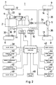
- an output of an engine 2 is inputted to a transfer 3 through a transmission 31.
- the transfer 3 has a center differential for equally transmitting an engine output to front and rear wheel sides.
- a front differential 4 is connected to an output shaft 32 on the front wheel side of the transfer 3.
- Right and left front wheels 6 and 7 are connected to the front differential 4 through a front wheel driving shaft 33.
- a rear differential 5 is connected to an output shaft 34 on the rear wheel side of the transfer 3.
- Right and left rear wheels 8 and 9 are connected to the rear differential 5 through a rear wheel driving shaft 35.
- a brake controller 10 as torque distribution change means includes a braking pressure control valve and an actuator.
- the braking pressure control valve separately controls the braking pressure to be supplied to braking devices 11 to 14 provided on the wheels 6 to 9.
- a throttle valve 36 of the engine 2 has its opening adjusted by a throttle motor 37.
- An engine controller 15 as engine output change means receives an accel signal from an accel sensor 38 which detects a quantity of accel operated by drivers, and then outputs an operation control signal to the throttle motor 37 so as to adjust the opening of the throttle valve 36 correspondingly to the quantity of accel operated by the drivers.
- the engine controller 15 receives a control signal from a torque distribution controller 16 as torque distribution control means and changes the engine output in order to obtain the engine output torque required to change the torque distribution.
- the torque distribution controller 16 receives signals from the accel sensor 38, and various signals for measuring an operation quantity or momentum for controlling the torque distribution for the wheels 6 to 9. Then, the torque distribution controller 16 outputs a control signal to the brake controller 10 and the engine controller 15.
- Output sources for the various signals are as follows; a steering angle sensor 40 for detecting a steering angle, a lateral acceleration sensor 41 for detecting a lateral acceleration of a car, a longitudinal acceleration sensor 42 for detecting a longitudinal acceleration of the car, a clutch sensor 43 for detecting the connection of a clutch, a wheel speed sensor 44 for detecting an engine speed of the wheels 6 to 9, an engine speed sensor 45 for detecting the engine speed, a car speed sensor 46, a gear position sensor 47 for detecting a gear position (gear speed) of a transmission 25, a boost sensor 48 for detecting a boost of the engine 2, and a yaw rate sensor 49 for detecting a yaw rate of the car.
- the torque distribution controller 16 includes a load movement correspondence control section having a longitudinal distribution control system for changing the torque distribution for the front wheels 6 and 7 and the rear wheels 8 and 9 (hereinafter referred to as longitudinal torque distribution if necessary), and a lateral distribution control system for changing the torque distribution for the left wheels 6 and 8 and the right wheels 7 and 9 (hereinafter referred to as lateral torque distribution if necessary), correspondingly to the load movement of the car which occurs by causing the longitudinal acceleration and lateral acceleration, a turning state correspondence control section having a longitudinal distribution control system for changing the longitudinal torque distribution, and a lateral distribution control system for changing the lateral torque distribution correspondingly to the turning state of the car, and a slip state correspondence control section having a longitudinal distribution control system for changing the longitudinal torque distribution, and a lateral distribution correspondingly to the slip state of the wheelscontrol system for changing the lateral torque distribution.
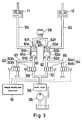
- a first hydraulic line for a braking device 11 of the left front wheel 6 and at 60 is indicated a second hydraulic line for the braking device 12 of the right front wheel 7.
- the first and second hydraulic lines 59 and 60 have first and second braking pressure control valves 61 and 62 provided therebetween.
- the first and second braking pressure control valves 61 and 62 control the supply of the braking pressure.
- the first and second braking pressure control valves 61 and 62 have cylinders 61a and 62a partitioned into variable volume chambers 61c and 62c, and control chambers 61d and 62d by pistons 61b and 62b.
- the variable volume chambers 61c and 62c supply the braking pressure generated by a master cylinder 58 to the braking devices 11 and 12.
- the pistons 61b and 62b are energized such that the volume of the variable volume chambers 61c and 62c is increased by springs 61e and 62e, and move such that the variable volume chambers 61c and 62c are reduced against the springs 61e and 62e by the control pressure introduced into the control chambers 61d and 62d. Furthermore, the pistons 61b and 62b have check valves 61f and 62f for closing braking pressure inlets of the variable volume chambers 61c and 62c according to the movement mentioned above. Accordingly, the control pressure is introduced into the control chambers 61d and 62d so that the pistons 61b and 62b move against the springs 61e and 62e. Consequently, there is blocked the space between the master cylinder 58 and the variable volume chambers 61c and 62c. In addition, the braking pressure in the variable volume chambers 61c and 62c is supplied to the braking devices 11 and 12.
- first and second actuators 63 and 64 having pressure increasing electromagnetic valves 63a and 64a and pressure reducing electromagnetic valves 63b and 64b to operate the braking pressure control valves 61 and 62.
- the pressure increasing electromagnetic valves 63a and 64a are provided on control pressure supply lines 69 and 70.
- the control pressure supply lines 69 and 70 are lead to the control chambers 61d and 62d of the braking pressure control valves 61 and 62 through an oil pump 65 and a relief valve 66.
- the pressure reducing electromagnetic valves 63b and 64b are provided on drain lines 67 and 68 which are lead from the control chambers 61d and 62d.
- the electromagnetic valves 63a, 63b, 64a and 64b are opened or closed by the signals from the torque distribution controller 16.
- the control pressure is introduced into the control chambers 61d and 62d of the braking pressure control valves 61 and 62.
- the pressure increasing electromagnetic valves 63a and 64a are closed and the pressure reducing electromagnetic valves 63b and 64b are opened, the control pressure is discharged from the control chambers 61d and 62d.
- the braking devices 13 and 14 of the right and left rear wheels 8 and 9, which are not shown, have the same structures as those of the braking devices 11 and 12 of the front wheels 6 and 7. With the above-mentioned structures, the independent braking pressure can be applied to the braking devices 11 to 14.
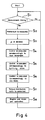
- Fig. 4 shows the entire flow of processing.
- the accel opening, steering angle, lateral acceleration, longitudinal acceleration, clutch connection, wheel speed, car speed, gear position, boost, and yaw rate are measured by the signals from the sensors 38, 40 to 49 shown in Fig. 2 (Steps S1 and S2).
- ⁇ of the road there are sequentially carried out the decision of ⁇ of the road, the determination of a torque distribution ratio Q1 of the front wheels 6 and 7 to the rear wheels 8 and 9 (hereinafter referred to as a longitudinal distribution ratio if necessary) and a torque distribution ratio Q2 of the left wheels 6 and 8 to the right wheels 7 and 9 (hereinafter referred to as a lateral distribution ratio if necessary) corresponding to the load movement, the determination of a longitudinal distribution ratio R1 and a lateral distribution ratio R2 corresponding to the turning state, and the determination of a longitudinal distribution ratio P1 and a lateral distribution ratio P2 corresponding to the slip state (Steps S3 to S6).
- a longitudinal distribution ratio Q1 of the front wheels 6 and 7 to the rear wheels 8 and 9 hereinafter referred to as a longitudinal distribution ratio if necessary
- a torque distribution ratio Q2 of the left wheels 6 and 8 to the right wheels 7 and 9 hereinafter referred to as a lateral distribution ratio if necessary
- a longitudinal distribution ratio K1 and a lateral distribution ratio K2 are corrected and determined on the basis of the torque distribution ratios Q1, R1, P1, Q2, R2 and P2 correspondingly to the torque obtained by changing the engine outputs. Consequently, the brake controller 10 and engine controller 15 are controlled (Steps S7 and S8).
- the longitudinal distribution ratio K1 and the like are set such that the longitudinal distribution is uniform at 0, the driving torque of the front wheels 6 and 7 is 0 (and that of the rear wheels 8 and 9 is the maximum) at +0.5, and the driving torque of the rear wheels 8 and 9 is 0 (and that of the front wheels 6 and 7 is the maximum) at -0.5.
- the lateral distribution ratio K2 and the like are set such that the lateral distribution is uniform at 0, the driving torque of the left wheels 6 and 8 is 0 (and that of the right wheels 7 and 9 is the maximum) at +0.5, and the driving torque of the right wheels 7 and 9 is 0 (and that of the left wheels 6 and 8 is the maximum) at -0.5.
- Friction coefficient decision means 20 presumes a friction coefficient ⁇ depending on the change of the wheel speed according to that of the driving force by utilizing the fact that the driving force is equal to 0 in the straight running state of the car when changing the gear speed change.
- ⁇ is decided by the following formula (Steps S11 to S13).
- ⁇ (slip rate variation) / (driving force variation)
- the driving force variation can be obtained as follows.
- the accel opening and an engine speed (RPM) are detected by the accel sensor 38 and engine speed sensor 45.
- the driving torque of the engine is calculated on the basis of the accel opening (accelerator pedal) and engine speed with reference to a map shown in Fig. 6. Then, the driving torque is multiplied by a gear ratio before gear speed change which is detected by the gear position sensor 47. Consequently, the driving force variation can be obtained.
- the present control is executed in accordance with a flow shown in Fig. 8. Basically, torque distribution control is executed by an actual lateral acceleration Glat and an actual longitudinal acceleration detected by the lateral acceleration sensor 41 and longitudinal acceleration sensor 42. In the case where the occurrence of the lateral acceleration is delayed for the steering on the low ⁇ road, Glat is corrected by an ideal non-delayed calculation lateral acceleration G.cal which is obtained on the high ⁇ road. In addition, the regions, in which the present control is executed, are changed correspondingly to ⁇ of the road.
- G.cal v 2 / (l + Av 2 ) ⁇ ⁇ / l
- v the lowest wheel speed of four wheel speeds obtained by the wheel speed sensor 44
- ⁇ a steering angle
- l a wheel base.
- A is a factor for obtaining the movement characteristics of the car on the high ⁇ road. The factor A is obtained with reference to a characteristic map shown in Fig. 9.
- G.cal and Glat are positive or negative and an absolute value of G.cal is smaller than that of Glat
- G.cal is replaced by Glat for control.
- Glat for control is forced to be 0 (Steps S22 to S25).
- Step S26 There is obtained a load movement rate Qlat between the left wheels 6 and 8 and the right wheels 7 and 9 by Glat for control. There is obtained a load movement rate Qlon between the front wheels 6 and 7 and the rear wheels 8 and 9 by the longitudinal acceleration (Step S26).
- a torque distribution ratio correction factor R is obtained by the constants GLIM1 and GLIM2.
- the correction factor R is multiplied by the longitudinal wheel load movement rate Qlon and the lateral wheel load movement ratio Qlat, respectively. Consequently, there can be obtained the longitudinal torque distribution ratio Q1 and lateral torque distribution ratio Q2 corresponding the load movement (Steps S27 and S28).
- the correction factor R corrects the torque distribution ratios Q1 and Q2 to be decreased when the acceleration is decreased.
- Step S27 As shown in a right diagram of Step S27, GLIM1 and GLIM2 are decreased and the difference thereof is reduced when ⁇ is made lower. In other words, a correction factor characteristic line is shifted to the left when ⁇ is made lower as shown in a dashed line in a left diagram of Step S27. Consequently, the region, in which the load movement correspondence control is executed, is enlarged toward the low acceleration side. In addition, even if the acceleration is low, the control can be executed with a great torque distribution ratio corresponding to the load movement rate. When ⁇ is high, the correction factor characteristic line is shifted to the right. Consequently, the load movement correspondence control is not executed until the acceleration is made comparatively high.
- the calculation lateral acceleration G.cal corrects Glat. Consequently, even if the comparatively great lateral acceleration remains after steering, the control corresponding to the lateral acceleration can be prevented. Accordingly, the control is executed after the steering so that the excessive force can be prevented from being applied to the car.
- the region, in which the present control is executed, is changed correspondingly to ⁇ of the road. Consequently, unnecessary torque distribution control can be inhibited on the high ⁇ road and the torque distribution control corresponding to the load movement can be executed on the low ⁇ road.
- the present control is executed in accordance with a flow shown in Fig. 10. Basically, the longitudinal distribution ratio R1 is determined on the basis of the lateral slide angle. Then, the lateral distribution ratio R2 is determined so as to obtain a target yaw rate. In addition, the distribution ratios R1 and R2 are corrected correspondingly to the turning state of the car.
- a turning state decision flag F means the following.
- F 0 ... ... straight running ;
- the steering angle is smaller than apredetermined value.
- F 1 ... ... turning start ;
- the change rate of steering angle is equal to or greater than a predetermined value in a plus direction (in which the steering angle is increased).
- F 2 ... ... constant turning (at nearly constant turning diameter) ;
- the steering angle is equal to or greater than the predetermined value, and the change rate of steering angle is smaller than the predetermined value.
- F 3 ... ... turning escape ;
- the change rate of steering angle is equal to or greater than the predetermined value in a minus direction (in which the steering angle is decreased).
- the longitudinal distribution ratio R1 is determined depending on a lateral slide angle and the lateral distribution ratio R2 is determined depending on the yaw rate (Steps S32 to S34). If the car is in the state of turning start and turning escape, the longitudinal distribution ratio R1 is corrected and controlled on the basis of the steering angle and change rate thereof (Steps S35 to S38).
- the longitudinal distribution ratio R1 is increased in the minus direction.
- the right turning is set in the plus direction. Accordingly, ⁇ having a plus or minus sign corresponds to the right or left turning of the car.
- the lateral distribution ratio R2 is determined depending on the yaw rate as follows. First, there is calculated the target yaw rate Y.cal on the high ⁇ road by the lowest wheel speed v, steering angle ⁇ and wheel base 1. Then, the lateral distribution ratio R2 is feed-back controlled so as to obtain the target yaw rate Y.cal from the difference between the target yaw rate Y.cal and the actual yaw rate Yaw. r.
- the target yaw rate Y.cal is obtained by the following formula.
- Y.cal v / (l + Av 2 ) ⁇ ⁇ / l where A is a factor obtained with reference to the characteristic map shown in Fig. 9.
- ⁇ Y Y.cal - Yaw.r is obtained so that R2 is determined by the following formula.
- R2 k ⁇ Y / Tr where Tr is driver request torque which is the same as the driving force variation for ⁇ decision mentioned above, and k is a constant (factor).
- the longitudinal distribution ratio R1 is set such that the torque distribution for the rear wheels 8 and 9 is decreased when the lateral slide angle is o23 increased. Consequently, if the lateral slip of the rear wheels 8 and 9 is increased during turning so that spin tendency is caused, the driving force of the rear wheels 8 and 9 is decreased without waiting for the decrease in quantity of drivers' steering. As a result, the lateral slip of the rear wheels 8 and 9 can be prevented so that the turning can be stabilized on the low ⁇ road.
- R1 is corrected so as to be increased at the time of turning start depending on the steering angle and change rate thereof. Consequently, the small turn of the car can be enhanced.
- R1 is corrected so as to be decreased at the time of turning escape. Therefore, the grip force of the rear wheels can be enhanced so as to stabilize the running.
- the lateral distribution ratio R2 is set by feed-back control in order to obtain the target yaw rate having the characteristics on the high ⁇ road. Consequently, the great yaw rate can be obtained on the low ⁇ road so as to enhance the turning steering.
- the present control is executed in accordance with a flow shown in Fig. 12, wherein the longitudinal distribution ratio P1 and lateral distribution ratio P2 are obtained depending on the slip rates of the front wheels 6 and 7 and the rear wheels 8 and 9 and those of the left wheels 6 and 8 and the right wheels 7 and 9.
- the slip rates S1 to S4 are obtained by the wheel speed sensors 44 for the wheels (Step S41).
- the representation in Step S41 of Fig. 12 means the following.
- the longitudinal distribution ratio P1 is set such that the torque distribution for the rear wheels is increased when the front wheel slip rate S1 is increased within the range of a predetermined value of S0 or more (Steps S42 and S43).
- the longitudinal distribution ratio P1 is set such that the torque distribution for the front wheels is increased when the left wheel slip rate S2 is increased within the range of the predetermined value of S0 or more (Steps S42 and S44).
- the lateral distribution ratio P2 is set such that the torque distribution for the left wheels is increased when the right wheel slip rate S3 is increased within the range of the predetermined value of S0 or more (Steps S45 and S46).
- the lateral distribution ratio P2 is set such that the torque distribution for the right wheels is increased when the left wheel slip rate S4 is increased within the range of the predetermined value of S0 or more (Steps S45 and S47).
- the longitudinal distribution ratio K1 and lateral distribution ratio K2 for the torque distribution control are corrected and determined correspondingly to the torque obtained by changing the engine outputs.
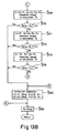
- the present control is executed in accordance with a flow shown in Fig. 13.
- the driver request torque Tr is calculated from the accel opening, engine speed and gear ratio with reference to the map shown in Fig. 6 (Step S51).
- the shaft output torque Teng is calculated depending on the boost and gear ratio obtained by the boost sensor 48 as follows (Steps S81 and S82).
- Teng A x (Bp - Bs) x Giar A ; boost torque constant Bp ; boost Bs ; boost reference value (driving force is zero) Giar ; gear ratio
- ⁇ 1 is an engine speed (the number of rotations of an input shaft) and ⁇ 2 is the average of the number of rotations of the wheel / gear ratio (the number of rotations of the output shaft) in a correction factor characteristic chart shown in Step S83. If the shaft output torque Teng is greater than the transmission torque Tc, Teng is restricted to Tc (Steps S85 and S86).
- the target torque Ttarg is compared with the transmission torque Tc. If Ttarg is greater than Tc, Ttarg is restricted to Tc (Steps S87 and S88).
- the shaft output torque Teng is greater than the required torque Ts obtained in Step S52, the shaft output torque can fully execute the torque distribution control (Teng > Ts in Step S54). Accordingly, the longitudinal distribution ratio K1 and lateral distribution ratio K2 are set as follows. In addition, Ts is set as the shaft output torque (Step S55). Consequently, the engine and brake are controlled (as described below).
- Step S60 K1 and K2 are corrected by the following formulas.
- K1 K1 ⁇ (Teng - Tr) / (Ts - Tr)
- K2 K2 ⁇ (Teng - Tr) / (Ts - Tr) Since the distribution ratios Q1 and Q2 are reduced, the shaft output torque Teng is made sufficient.
- the distribution ratios K1 and K2 are corrected so as to approximate to the distribution ratios in Step S52.
- the correction is executed such that the reduced distribution ratios (Q1 and Q2) are partially returned as much as possible.
- the shaft output torque Teng is set as the required torque Ts in Step S55.
- Step S64 The shaft output torque Teng is compared with the required torque Ts (Step S64). If Teng is greater than Ts, this routine proceeds to Step S60 at which K1 and K2 are corrected. Then, Ts is set at Step S55.
- the shaft output torque Teng is compared with the required torque Ts (Step S68). If Teng is greater than Ts, this routine proceeds to Step S60. If the shaft output torque Teng is smaller than the required torque Ts, this routine proceeds to Step S65.
- this routine proceeds to Step S60. If Teng is not finally greater than Ts, this routine proceeds to Step S65 (Steps S69 to S74).
- the engine controller 15 and brake controller 10 are controlled on the basis of the required torque Ts (target torque Ttarg) and the longitudinal and lateral distribution ratios K1 and K2 in accordance with a flow shown in Fig. 15.
- throttle opening THR is obtained with reference to an output torque / throttle opening characteristic map (Steps S91 and S92).
- Ttarg Ttarg / Giar
- the throttle opening of the engine 2 is set to THR by the engine controller 15. In this case, if THR is smaller than accel opening ACC depending on the drivers' operation, the engine controller 15 is controlled so as to obtain the throttle opening corresponding to the accel opening ACC (Steps S93 to S95).
- TBFR Teng - 4(0.5 - K1) x (0.5 + K2) x Ts
- TBFL Teng - 4(0.5 - K1) x (0.5 - K2) x Ts
- TBRR Teng - 4(0.5 + K1) x (0.5 + K2) x Ts
- TBRL Teng - 4(0.5 + K1) x (0.5 - K2) x Ts
- the torque distribution for the rear wheels is decreased at the time of turning escape so that the slip or excessive autorotation of the wheels can be smoothly prevented from being caused. Thus, the straight running can be smoothly attained at the time of turning escape.
- the load movement correspondence control or lateral distribution control is executed with priority during turning. Consequently, the driving torque 13 corresponding to the load movement is applied to the wheels so that the slip of the wheels can be prevented and the turning can be enhanced.
Landscapes
- Engineering & Computer Science (AREA)
- Chemical & Material Sciences (AREA)
- Combustion & Propulsion (AREA)
- Transportation (AREA)
- Mechanical Engineering (AREA)
- Arrangement And Driving Of Transmission Devices (AREA)
- Control Of Driving Devices And Active Controlling Of Vehicle (AREA)
- Regulating Braking Force (AREA)
- Control Of Vehicle Engines Or Engines For Specific Uses (AREA)
- Electrical Control Of Air Or Fuel Supplied To Internal-Combustion Engine (AREA)
Claims (2)
- Vorrichtung zur Steuerung der Drehmomentverteilung für einen Vierradantrieb, bei dem die vier Räder (6, 7, 8, 9) eines Kraftfahrzeugs über eine Anzahl von Ausgangsleistungen angetrieben werden und die Antriebsdrehmomentverteilung für die vier Räder verändert wird, mit einer Einrichtung (10) zur Änderung der Drehmomentverteilung, mit welcher die Grösse der auf die vier Räder zu übertragenden Motorausgangsleistungen eingestellt wird dergestalt, dass die Drehmomentverteilung geändert wird; einer Einrichtung (15) zur Änderung der Motorausgangsleistung, welche die Motorausgangsleistungen so erhöht, dass das zur Änderung der Drehmomentverteilung erforderliche Drehkompensiert wird; einer Einrichtung (20) zur Erfassung des Reibungskeoffizienten der Strasse; einer Fahrzustand-Erfassungseinrichtung (21) zum Erfassen des Kurveneinfahr- und Kurvenausfahrzustandes des Fahrzeugs; einer Einrichtung (16) zur Steuerung der Drehmomentverteilung mit einem Längsverteilungs-Steuersystem zur Änderung der Drehmomentverteilung für die Vorder- und Hinterräder und einem Querverteilungs-Steuersystem zur Änderung der Drehmomentverteilung für die rechten und linken Räder sowie zum Steuern der Einrichtung (10) zur Änderung der Drehmomentverteilung und der Einrichtung (15) zur Änderung der Motorausgangsleistungen entsprechend den jeweiligen Fahr- bzw. Betriebsbedingungen des Fahrzeugs; und einer Steuersystem-Wähleinrichtung (19), welche das zur Ausführung des Steuervorgangs jeweils in Abhängigkeit vom Reibungskoeffizienten der Strasse und dem Fahrzustand des Fahrzeugs passende Steuersystem auswählt, dadurch gekennzeichnet, dass die Steuersystem-Wähleinrichtung (19) jeweils vorrangig auswählt das Querverteilungs-Steuersystem zum Zeitpunkt der Kurveneinfahrt, wenn der Reibungskoeffizient der Strasse niedrig ist, das Längsverteilungs-Steuersystem zum Zeitpunkt der Kurvenausfahrt, wenn die Strasse einen niedrigen Reibungskoeffizienten aufweist, und das Querverteilungs-Steuersystem beim Kurvenfahren auf einer Fahrbahn mit hohem Reibungskoeffizienten.
- Vorrichtung zur Steuerung der Drehmomentverteilung für einen Vierradantrieb, bei dem die vier Räder (6, 7, 8, 9) eines Kraftfahrzeugs über eine Anzahl von Ausgangsleistungen angetrieben werden und die Antriebsdrehmomentverteilung für die vier Räder verändert wird, mit einer Einrichtung (10) zur Änderung der Drehmomentverteilung, mit welcher die Grösse der auf die vier Räder zu übertragenden Motorausgangsleistungen eingestellt wird dergestalt, dass die Drehmomentverteilung geändert wird; einer Einrichtung (15) zur Änderung der Motorausgangsleistung, welche die Motorausgangsleistungen so erhöht, dass das zur Änderung der Drehmomentverteilung erforderliche Drehkompensiert wird; einer Einrichtung (20) zur Erfassung des Reibungskeoffizienten der Strasse; einer Fahrzustand-Erfassungseinrichtung (21) zum Erfassen des Kurveneinfahr- und Kurvenausfahrzustandes des Fahrzeugs; einer Einrichtung (16) zur Steuerung der Drehmomentverteilung mit einer Anzahl von Steuersystemen zum Einstellen des Drehmomentverteilungsverhältnisses für die vier Räder und sowie zum Steuern der Einrichtung (10) zur Änderung der Drehmomentverteilung und der Einrichtung (15) zur Änderung der Motorausgangsleistungen entsprechend den jeweiligen Fahr- bzw. Betriebsbedingungen des Fahrzeugs; und einer Steuersystem-Wähleinrichtung (19), welche das zur Ausführung des Steuervorgangs jeweils in Abhängigkeit vom Reibungskoeffizienten der Strasse und dem Fahrzustand des Fahrzeugs passende Steuersystem auswählt, dadurch gekennzeichnet, dass die Einrichtung (16) zur Steuerung der Drehmomentverteilung aufweist ein Lastverschiebungs-Korrespondenzsteuersystem zur Änderung der Drehmomentverteilung für die vier Räder entsprechend der jeweiligen Lastverschiebung beim Fahrzeug, ein Fahrzustand-Korrespondenzsteuersystem zur Änderung der Drehmomentverteilung für die vier Räder entsprechend dem Kurvenfahrzustand des Fahrzeugs, und ein Schlupfzustand-Korrespondenzsteuersstem zur Änderung der Drehmomentverteilung für die vier Räder entsprechend dem Schlupfzustand derselben; und die Steuersystem-Wähleinrichtung (19) aufeinanderfolgend die Korrespondenzsteuersysteme für Schlupfzustand, Kurvenfahrzustand und Lastverschiebung vorrangig zum Zeitpunkt der Kurveneinfahrt sowie vorrangig bei der Kurvenausfahrt auswählt, wenn der Reibungskoeffizient der Strasse niedrig ist.
Applications Claiming Priority (2)
| Application Number | Priority Date | Filing Date | Title |
|---|---|---|---|
| JP105954/90 | 1990-04-20 | ||
| JP10595490A JP3221873B2 (ja) | 1990-04-20 | 1990-04-20 | 4輪駆動車のトルク配分制御装置 |
Publications (3)
| Publication Number | Publication Date |
|---|---|
| EP0453931A2 EP0453931A2 (de) | 1991-10-30 |
| EP0453931A3 EP0453931A3 (en) | 1992-09-02 |
| EP0453931B1 true EP0453931B1 (de) | 1996-07-10 |
Family
ID=14421222
Family Applications (1)
| Application Number | Title | Priority Date | Filing Date |
|---|---|---|---|
| EP91106076A Expired - Lifetime EP0453931B1 (de) | 1990-04-20 | 1991-04-17 | Vorrichtung zur Steuerung der Drehmomentverteilung für einen Vierradantrieb |
Country Status (4)
| Country | Link |
|---|---|
| US (1) | US5262950A (de) |
| EP (1) | EP0453931B1 (de) |
| JP (1) | JP3221873B2 (de) |
| DE (1) | DE69120721T2 (de) |
Cited By (11)
| Publication number | Priority date | Publication date | Assignee | Title |
|---|---|---|---|---|
| US5694321A (en) | 1994-11-25 | 1997-12-02 | Itt Automotive Europe Gmbh | System for integrated driving stability control |
| US5701248A (en) | 1994-11-25 | 1997-12-23 | Itt Automotive Europe Gmbh | Process for controlling the driving stability with the king pin inclination difference as the controlled variable |
| US5710704A (en) | 1994-11-25 | 1998-01-20 | Itt Automotive Europe Gmbh | System for driving stability control during travel through a curve |
| US5711025A (en) | 1994-11-25 | 1998-01-20 | Itt Automotive Europe Gmbh | Driving stability control system with selective brake actuation |
| US5711024A (en) | 1994-11-25 | 1998-01-20 | Itt Automotive Europe Gmbh | System for controlling yaw moment based on an estimated coefficient of friction |
| US5710705A (en) | 1994-11-25 | 1998-01-20 | Itt Automotive Europe Gmbh | Method for determining an additional yawing moment based on side slip angle velocity |
| US5732378A (en) | 1994-11-25 | 1998-03-24 | Itt Automotive Europe Gmbh | Method for determining a wheel brake pressure |
| US5732377A (en) | 1994-11-25 | 1998-03-24 | Itt Automotive Europe Gmbh | Process for controlling driving stability with a yaw rate sensor equipped with two lateral acceleration meters |
| US5732379A (en) | 1994-11-25 | 1998-03-24 | Itt Automotive Europe Gmbh | Brake system for a motor vehicle with yaw moment control |
| US5742507A (en) | 1994-11-25 | 1998-04-21 | Itt Automotive Europe Gmbh | Driving stability control circuit with speed-dependent change of the vehicle model |
| US5774821A (en) | 1994-11-25 | 1998-06-30 | Itt Automotive Europe Gmbh | System for driving stability control |
Families Citing this family (20)
| Publication number | Priority date | Publication date | Assignee | Title |
|---|---|---|---|---|
| GB9109094D0 (en) * | 1991-04-26 | 1991-06-12 | Motor Sport Developments Ltd | Motor vehicle transmission control |
| JP2704804B2 (ja) * | 1992-02-04 | 1998-01-26 | 本田技研工業株式会社 | 車両のトラクションコントロール装置 |
| JP3192768B2 (ja) * | 1992-09-03 | 2001-07-30 | 日産自動車株式会社 | 前後輪駆動力配分とトラクションとの総合制御装置 |
| US5433283A (en) * | 1993-10-27 | 1995-07-18 | Sgs-Thomson Microelectronics, Inc. | Apparatus for controlling a throttle plate of a carburetor of an internal combustion engine in response to loss of traction by a driving wheel, or other similar condition |
| JP3033416B2 (ja) * | 1993-12-28 | 2000-04-17 | 日産自動車株式会社 | 車両の前後輪間駆動力配分制御装置 |
| JP3268124B2 (ja) * | 1994-06-27 | 2002-03-25 | 富士重工業株式会社 | 車両のトルク配分制御装置 |
| JP3475559B2 (ja) * | 1995-03-28 | 2003-12-08 | 日産自動車株式会社 | 車両の駆動力制御装置 |
| JP3358452B2 (ja) * | 1996-07-22 | 2002-12-16 | 日産自動車株式会社 | 車両のエンジンブレーキ制御装置 |
| DE19950205C1 (de) * | 1999-10-19 | 2000-11-02 | Bayerische Motoren Werke Ag | Steuersystem zur variablen Drehmomentverteilung für ein vierradgetriebenes Fahrzeug |
| JP2001260836A (ja) * | 2000-03-23 | 2001-09-26 | Toyota Motor Corp | 車両用駆動力配分制御装置 |
| SE519300C2 (sv) * | 2000-10-31 | 2003-02-11 | Saab Automobile | Motorfordon med fyra drivbara hjul samt sätt att driva detta |
| US6889132B2 (en) * | 2001-02-01 | 2005-05-03 | Ford Global Technologies, Llc | Vehicle drive control for 4×4 mode |
| DE10245035A1 (de) * | 2002-09-26 | 2004-04-08 | Dr.Ing.H.C. F. Porsche Ag | Verfahren zur Regelung des Fahrverhaltens mittels Einflussnahme zur Vermeidung des Untersteuerns |
| DE10245032A1 (de) * | 2002-09-26 | 2004-04-08 | Dr.Ing.H.C. F. Porsche Ag | Verfahren zur Regelung des Fahrverhaltens mittels Einflussnahme auf die Giergeschwindigkeit |
| DE602005016982D1 (de) | 2004-03-31 | 2009-11-19 | Honda Motor Co Ltd | Antriebskraft- Steuerungsverfahren für vierradgetriebenes Fahrzeug |
| JP4684618B2 (ja) * | 2004-10-21 | 2011-05-18 | 富士重工業株式会社 | 車両の駆動力配分制御装置 |
| DE102010012153A1 (de) * | 2010-03-20 | 2011-09-22 | Audi Ag | Fahrzeug mit zumindest zwei Einzelradantriebseinheit |
| KR101734582B1 (ko) * | 2011-11-29 | 2017-05-12 | 현대자동차주식회사 | Vrs를 이용한 4wd 시스템 및 이를 이용한 제어방법 |
| CN114987440B (zh) * | 2022-04-26 | 2025-05-16 | 上海汽车变速器有限公司 | 驱动防滑控制方法、装置、设备及存储介质 |
| DE112022007138T5 (de) * | 2022-04-26 | 2025-02-27 | Gkn Automotive Limited | Antriebssystem |
Family Cites Families (11)
| Publication number | Priority date | Publication date | Assignee | Title |
|---|---|---|---|---|
| JPH0615325B2 (ja) * | 1985-10-11 | 1994-03-02 | 日産自動車株式会社 | ホイールスピン検出装置 |
| US4702341A (en) * | 1985-12-13 | 1987-10-27 | Toyota Jidosha Kabushiki Kaisha | Four wheel drive vehicle slippage control device and method limiting center differential action according to input torque supplied thereto |
| EP0236694B1 (de) * | 1986-03-11 | 1990-11-28 | Dr.Ing.h.c. F. Porsche Aktiengesellschaft | Anordnung zur Steuerung der Kraftübertragung eines vierradangetriebenen Fahrzeuges |
| JPH064389B2 (ja) * | 1986-04-01 | 1994-01-19 | マツダ株式会社 | 自動車の定速走行制御装置 |
| US4896738A (en) * | 1986-06-20 | 1990-01-30 | Fuji Jukogyo Kabushiki Kaisha | Power transmitting system for a four-wheel drive vehicle |
| JP2683655B2 (ja) * | 1988-03-28 | 1997-12-03 | マツダ株式会社 | 4輪駆動車のトルク配分装置 |
| JPH0725278B2 (ja) * | 1988-08-31 | 1995-03-22 | 日産自動車株式会社 | 四輪駆動車の駆動力配分制御装置 |
| JP2693204B2 (ja) * | 1989-01-31 | 1997-12-24 | マツダ株式会社 | 4輪駆動車のトルク分配制御装置 |
| JPH0729558B2 (ja) * | 1989-04-10 | 1995-04-05 | 日産自動車株式会社 | 四輪駆動車の駆動力配分制御装置 |
| JPH0794207B2 (ja) * | 1989-04-19 | 1995-10-11 | 日産自動車株式会社 | 四輪駆動車の駆動力配分制御装置 |
| JPH02290737A (ja) * | 1989-04-28 | 1990-11-30 | Fuji Heavy Ind Ltd | 4輪駆動車の駆動力配分制御装置 |
-
1990
- 1990-04-20 JP JP10595490A patent/JP3221873B2/ja not_active Expired - Fee Related
-
1991
- 1991-04-17 DE DE69120721T patent/DE69120721T2/de not_active Expired - Fee Related
- 1991-04-17 EP EP91106076A patent/EP0453931B1/de not_active Expired - Lifetime
- 1991-04-18 US US07/686,627 patent/US5262950A/en not_active Expired - Lifetime
Cited By (13)
| Publication number | Priority date | Publication date | Assignee | Title |
|---|---|---|---|---|
| US5694321A (en) | 1994-11-25 | 1997-12-02 | Itt Automotive Europe Gmbh | System for integrated driving stability control |
| US5701248A (en) | 1994-11-25 | 1997-12-23 | Itt Automotive Europe Gmbh | Process for controlling the driving stability with the king pin inclination difference as the controlled variable |
| US5710704A (en) | 1994-11-25 | 1998-01-20 | Itt Automotive Europe Gmbh | System for driving stability control during travel through a curve |
| US5711025A (en) | 1994-11-25 | 1998-01-20 | Itt Automotive Europe Gmbh | Driving stability control system with selective brake actuation |
| US5711024A (en) | 1994-11-25 | 1998-01-20 | Itt Automotive Europe Gmbh | System for controlling yaw moment based on an estimated coefficient of friction |
| US5710705A (en) | 1994-11-25 | 1998-01-20 | Itt Automotive Europe Gmbh | Method for determining an additional yawing moment based on side slip angle velocity |
| US5711023A (en) | 1994-11-25 | 1998-01-20 | Itt Automotive Europe Gmbh | System for determining side slip angle |
| US5732378A (en) | 1994-11-25 | 1998-03-24 | Itt Automotive Europe Gmbh | Method for determining a wheel brake pressure |
| US5732377A (en) | 1994-11-25 | 1998-03-24 | Itt Automotive Europe Gmbh | Process for controlling driving stability with a yaw rate sensor equipped with two lateral acceleration meters |
| US5732379A (en) | 1994-11-25 | 1998-03-24 | Itt Automotive Europe Gmbh | Brake system for a motor vehicle with yaw moment control |
| US5742507A (en) | 1994-11-25 | 1998-04-21 | Itt Automotive Europe Gmbh | Driving stability control circuit with speed-dependent change of the vehicle model |
| US5774821A (en) | 1994-11-25 | 1998-06-30 | Itt Automotive Europe Gmbh | System for driving stability control |
| US5862503A (en) | 1994-11-25 | 1999-01-19 | Itt Automotive Europe Gmbh | System for driving stability control |
Also Published As
| Publication number | Publication date |
|---|---|
| EP0453931A2 (de) | 1991-10-30 |
| EP0453931A3 (en) | 1992-09-02 |
| JPH045134A (ja) | 1992-01-09 |
| DE69120721D1 (de) | 1996-08-14 |
| US5262950A (en) | 1993-11-16 |
| JP3221873B2 (ja) | 2001-10-22 |
| DE69120721T2 (de) | 1997-01-23 |
Similar Documents
| Publication | Publication Date | Title |
|---|---|---|
| EP0453931B1 (de) | Vorrichtung zur Steuerung der Drehmomentverteilung für einen Vierradantrieb | |
| US5265020A (en) | Torque distribution control apparatus for four wheel drive | |
| US5225984A (en) | Torque distribution control apparatus for four wheel drive | |
| EP0461570B1 (de) | Drehmomentverteilungssteuerung eines Vierradantriebs | |
| EP0352110B1 (de) | Verfahren zum gemeinsamen Steuern eines stufenlosen Getriebes und einer Gassteuerung eines Verbrennungsmotors | |
| US5277286A (en) | Method of controlling automatic clutch for motor vehicles | |
| US4953654A (en) | Vehicular differential limiting torque control system | |
| US4804074A (en) | Automatic clutch control apparatus | |
| EP0389262B1 (de) | Verfahren zur Steuerung eines stufenlosen Getriebes in Verbindung mit der Steuerung der Motordrosselklappe | |
| EP0424088B1 (de) | Steuerungssystem für ein automatisches Getriebe | |
| EP1177934B1 (de) | Übersetzungssteuerung für ein stufenloses Getriebe | |
| JP3572377B2 (ja) | 車両用駆動力制御装置 | |
| US6009968A (en) | Control apparatus method for four-wheel drive vehicle | |
| US5181175A (en) | Drive wheel slip control system for vehicle | |
| KR20000028856A (ko) | 차량 주행시에 변속비 변화에 연관된 전위 과정을제어하는 방법 | |
| EP0317290A2 (de) | Steuerungsverfahren für das Übersetzungsverhältnis eines stufenlos verstellbaren Getriebes | |
| JPH0719337A (ja) | 自動変速機のクリープトルク制御装置 | |
| JP3728896B2 (ja) | 車両用走行制御装置 | |
| EP0552942B1 (de) | Verfahren zur Steuerung stufenloser Getriebe | |
| JPH05319124A (ja) | 4輪駆動車の走行制御装置 | |
| JP2851378B2 (ja) | 4輪駆動車のトルク配分制御装置 | |
| JP2837897B2 (ja) | 車両用加速スリップ制御装置 | |
| JP2851386B2 (ja) | 4輪駆動車のトルク配分制御装置 | |
| JP4254428B2 (ja) | 四輪駆動車の駆動力配分制御装置 | |
| JP2859697B2 (ja) | 4輪駆動車のトルク配分制御装置 |
Legal Events
| Date | Code | Title | Description |
|---|---|---|---|
| PUAI | Public reference made under article 153(3) epc to a published international application that has entered the european phase |
Free format text: ORIGINAL CODE: 0009012 |
|
| AK | Designated contracting states |
Kind code of ref document: A2 Designated state(s): DE FR GB SE |
|
| PUAL | Search report despatched |
Free format text: ORIGINAL CODE: 0009013 |
|
| AK | Designated contracting states |
Kind code of ref document: A3 Designated state(s): DE FR GB SE |
|
| 17P | Request for examination filed |
Effective date: 19930223 |
|
| 17Q | First examination report despatched |
Effective date: 19940224 |
|
| GRAH | Despatch of communication of intention to grant a patent |
Free format text: ORIGINAL CODE: EPIDOS IGRA |
|
| GRAA | (expected) grant |
Free format text: ORIGINAL CODE: 0009210 |
|
| AK | Designated contracting states |
Kind code of ref document: B1 Designated state(s): DE FR GB SE |
|
| ET | Fr: translation filed | ||
| REF | Corresponds to: |
Ref document number: 69120721 Country of ref document: DE Date of ref document: 19960814 |
|
| PG25 | Lapsed in a contracting state [announced via postgrant information from national office to epo] |
Ref country code: GB Effective date: 19970417 |
|
| PG25 | Lapsed in a contracting state [announced via postgrant information from national office to epo] |
Ref country code: SE Effective date: 19970418 |
|
| PLBE | No opposition filed within time limit |
Free format text: ORIGINAL CODE: 0009261 |
|
| STAA | Information on the status of an ep patent application or granted ep patent |
Free format text: STATUS: NO OPPOSITION FILED WITHIN TIME LIMIT |
|
| 26N | No opposition filed | ||
| GBPC | Gb: european patent ceased through non-payment of renewal fee |
Effective date: 19970417 |
|
| PG25 | Lapsed in a contracting state [announced via postgrant information from national office to epo] |
Ref country code: FR Free format text: LAPSE BECAUSE OF NON-PAYMENT OF DUE FEES Effective date: 19971231 |
|
| EUG | Se: european patent has lapsed |
Ref document number: 91106076.2 |
|
| REG | Reference to a national code |
Ref country code: FR Ref legal event code: ST |
|
| PGFP | Annual fee paid to national office [announced via postgrant information from national office to epo] |
Ref country code: DE Payment date: 20010409 Year of fee payment: 11 |
|
| PG25 | Lapsed in a contracting state [announced via postgrant information from national office to epo] |
Ref country code: DE Free format text: LAPSE BECAUSE OF NON-PAYMENT OF DUE FEES Effective date: 20021101 |