EP0424088B1 - Steuerungssystem für ein automatisches Getriebe - Google Patents
Steuerungssystem für ein automatisches Getriebe Download PDFInfo
- Publication number
- EP0424088B1 EP0424088B1 EP90311317A EP90311317A EP0424088B1 EP 0424088 B1 EP0424088 B1 EP 0424088B1 EP 90311317 A EP90311317 A EP 90311317A EP 90311317 A EP90311317 A EP 90311317A EP 0424088 B1 EP0424088 B1 EP 0424088B1
- Authority
- EP
- European Patent Office
- Prior art keywords
- target
- acceleration
- engine
- rotational speed
- motor vehicle
- Prior art date
- Legal status (The legal status is an assumption and is not a legal conclusion. Google has not performed a legal analysis and makes no representation as to the accuracy of the status listed.)
- Expired - Lifetime
Links
- 230000005540 biological transmission Effects 0.000 title claims description 57
- 238000000034 method Methods 0.000 title claims description 37
- 230000001133 acceleration Effects 0.000 claims description 131
- 230000008859 change Effects 0.000 claims description 42
- 230000009467 reduction Effects 0.000 claims description 29
- 238000006073 displacement reaction Methods 0.000 claims description 9
- 230000004044 response Effects 0.000 claims description 3
- 230000001276 controlling effect Effects 0.000 description 19
- 230000008569 process Effects 0.000 description 7
- 230000000994 depressogenic effect Effects 0.000 description 6
- 230000001105 regulatory effect Effects 0.000 description 6
- 230000007246 mechanism Effects 0.000 description 5
- 238000004891 communication Methods 0.000 description 4
- 238000010586 diagram Methods 0.000 description 4
- 230000002093 peripheral effect Effects 0.000 description 2
- 239000002826 coolant Substances 0.000 description 1
- 230000000694 effects Effects 0.000 description 1
- 239000000446 fuel Substances 0.000 description 1
- 238000012986 modification Methods 0.000 description 1
- 230000004048 modification Effects 0.000 description 1
Images




Classifications
-
- B—PERFORMING OPERATIONS; TRANSPORTING
- B60—VEHICLES IN GENERAL
- B60W—CONJOINT CONTROL OF VEHICLE SUB-UNITS OF DIFFERENT TYPE OR DIFFERENT FUNCTION; CONTROL SYSTEMS SPECIALLY ADAPTED FOR HYBRID VEHICLES; ROAD VEHICLE DRIVE CONTROL SYSTEMS FOR PURPOSES NOT RELATED TO THE CONTROL OF A PARTICULAR SUB-UNIT
- B60W10/00—Conjoint control of vehicle sub-units of different type or different function
- B60W10/04—Conjoint control of vehicle sub-units of different type or different function including control of propulsion units
- B60W10/06—Conjoint control of vehicle sub-units of different type or different function including control of propulsion units including control of combustion engines
-
- B—PERFORMING OPERATIONS; TRANSPORTING
- B60—VEHICLES IN GENERAL
- B60W—CONJOINT CONTROL OF VEHICLE SUB-UNITS OF DIFFERENT TYPE OR DIFFERENT FUNCTION; CONTROL SYSTEMS SPECIALLY ADAPTED FOR HYBRID VEHICLES; ROAD VEHICLE DRIVE CONTROL SYSTEMS FOR PURPOSES NOT RELATED TO THE CONTROL OF A PARTICULAR SUB-UNIT
- B60W10/00—Conjoint control of vehicle sub-units of different type or different function
- B60W10/04—Conjoint control of vehicle sub-units of different type or different function including control of propulsion units
-
- B—PERFORMING OPERATIONS; TRANSPORTING
- B60—VEHICLES IN GENERAL
- B60W—CONJOINT CONTROL OF VEHICLE SUB-UNITS OF DIFFERENT TYPE OR DIFFERENT FUNCTION; CONTROL SYSTEMS SPECIALLY ADAPTED FOR HYBRID VEHICLES; ROAD VEHICLE DRIVE CONTROL SYSTEMS FOR PURPOSES NOT RELATED TO THE CONTROL OF A PARTICULAR SUB-UNIT
- B60W10/00—Conjoint control of vehicle sub-units of different type or different function
- B60W10/10—Conjoint control of vehicle sub-units of different type or different function including control of change-speed gearings
- B60W10/101—Infinitely variable gearings
-
- B—PERFORMING OPERATIONS; TRANSPORTING
- B60—VEHICLES IN GENERAL
- B60W—CONJOINT CONTROL OF VEHICLE SUB-UNITS OF DIFFERENT TYPE OR DIFFERENT FUNCTION; CONTROL SYSTEMS SPECIALLY ADAPTED FOR HYBRID VEHICLES; ROAD VEHICLE DRIVE CONTROL SYSTEMS FOR PURPOSES NOT RELATED TO THE CONTROL OF A PARTICULAR SUB-UNIT
- B60W10/00—Conjoint control of vehicle sub-units of different type or different function
- B60W10/10—Conjoint control of vehicle sub-units of different type or different function including control of change-speed gearings
- B60W10/11—Stepped gearings
-
- B—PERFORMING OPERATIONS; TRANSPORTING
- B60—VEHICLES IN GENERAL
- B60W—CONJOINT CONTROL OF VEHICLE SUB-UNITS OF DIFFERENT TYPE OR DIFFERENT FUNCTION; CONTROL SYSTEMS SPECIALLY ADAPTED FOR HYBRID VEHICLES; ROAD VEHICLE DRIVE CONTROL SYSTEMS FOR PURPOSES NOT RELATED TO THE CONTROL OF A PARTICULAR SUB-UNIT
- B60W30/00—Purposes of road vehicle drive control systems not related to the control of a particular sub-unit, e.g. of systems using conjoint control of vehicle sub-units
- B60W30/18—Propelling the vehicle
- B60W30/1819—Propulsion control with control means using analogue circuits, relays or mechanical links
-
- B—PERFORMING OPERATIONS; TRANSPORTING
- B60—VEHICLES IN GENERAL
- B60W—CONJOINT CONTROL OF VEHICLE SUB-UNITS OF DIFFERENT TYPE OR DIFFERENT FUNCTION; CONTROL SYSTEMS SPECIALLY ADAPTED FOR HYBRID VEHICLES; ROAD VEHICLE DRIVE CONTROL SYSTEMS FOR PURPOSES NOT RELATED TO THE CONTROL OF A PARTICULAR SUB-UNIT
- B60W30/00—Purposes of road vehicle drive control systems not related to the control of a particular sub-unit, e.g. of systems using conjoint control of vehicle sub-units
- B60W30/18—Propelling the vehicle
- B60W30/188—Controlling power parameters of the driveline, e.g. determining the required power
-
- F—MECHANICAL ENGINEERING; LIGHTING; HEATING; WEAPONS; BLASTING
- F16—ENGINEERING ELEMENTS AND UNITS; GENERAL MEASURES FOR PRODUCING AND MAINTAINING EFFECTIVE FUNCTIONING OF MACHINES OR INSTALLATIONS; THERMAL INSULATION IN GENERAL
- F16H—GEARING
- F16H61/00—Control functions within control units of change-speed- or reversing-gearings for conveying rotary motion ; Control of exclusively fluid gearing, friction gearing, gearings with endless flexible members or other particular types of gearing
- F16H61/02—Control functions within control units of change-speed- or reversing-gearings for conveying rotary motion ; Control of exclusively fluid gearing, friction gearing, gearings with endless flexible members or other particular types of gearing characterised by the signals used
- F16H61/0202—Control functions within control units of change-speed- or reversing-gearings for conveying rotary motion ; Control of exclusively fluid gearing, friction gearing, gearings with endless flexible members or other particular types of gearing characterised by the signals used the signals being electric
- F16H61/0204—Control functions within control units of change-speed- or reversing-gearings for conveying rotary motion ; Control of exclusively fluid gearing, friction gearing, gearings with endless flexible members or other particular types of gearing characterised by the signals used the signals being electric for gearshift control, e.g. control functions for performing shifting or generation of shift signal
- F16H61/0213—Control functions within control units of change-speed- or reversing-gearings for conveying rotary motion ; Control of exclusively fluid gearing, friction gearing, gearings with endless flexible members or other particular types of gearing characterised by the signals used the signals being electric for gearshift control, e.g. control functions for performing shifting or generation of shift signal characterised by the method for generating shift signals
-
- F—MECHANICAL ENGINEERING; LIGHTING; HEATING; WEAPONS; BLASTING
- F16—ENGINEERING ELEMENTS AND UNITS; GENERAL MEASURES FOR PRODUCING AND MAINTAINING EFFECTIVE FUNCTIONING OF MACHINES OR INSTALLATIONS; THERMAL INSULATION IN GENERAL
- F16H—GEARING
- F16H61/00—Control functions within control units of change-speed- or reversing-gearings for conveying rotary motion ; Control of exclusively fluid gearing, friction gearing, gearings with endless flexible members or other particular types of gearing
- F16H61/38—Control of exclusively fluid gearing
- F16H61/40—Control of exclusively fluid gearing hydrostatic
- F16H61/42—Control of exclusively fluid gearing hydrostatic involving adjustment of a pump or motor with adjustable output or capacity
- F16H61/425—Motor capacity control by electric actuators
-
- F—MECHANICAL ENGINEERING; LIGHTING; HEATING; WEAPONS; BLASTING
- F16—ENGINEERING ELEMENTS AND UNITS; GENERAL MEASURES FOR PRODUCING AND MAINTAINING EFFECTIVE FUNCTIONING OF MACHINES OR INSTALLATIONS; THERMAL INSULATION IN GENERAL
- F16H—GEARING
- F16H61/00—Control functions within control units of change-speed- or reversing-gearings for conveying rotary motion ; Control of exclusively fluid gearing, friction gearing, gearings with endless flexible members or other particular types of gearing
- F16H61/38—Control of exclusively fluid gearing
- F16H61/40—Control of exclusively fluid gearing hydrostatic
- F16H61/46—Automatic regulation in accordance with output requirements
- F16H61/47—Automatic regulation in accordance with output requirements for achieving a target output speed
-
- F—MECHANICAL ENGINEERING; LIGHTING; HEATING; WEAPONS; BLASTING
- F16—ENGINEERING ELEMENTS AND UNITS; GENERAL MEASURES FOR PRODUCING AND MAINTAINING EFFECTIVE FUNCTIONING OF MACHINES OR INSTALLATIONS; THERMAL INSULATION IN GENERAL
- F16H—GEARING
- F16H61/00—Control functions within control units of change-speed- or reversing-gearings for conveying rotary motion ; Control of exclusively fluid gearing, friction gearing, gearings with endless flexible members or other particular types of gearing
- F16H61/66—Control functions within control units of change-speed- or reversing-gearings for conveying rotary motion ; Control of exclusively fluid gearing, friction gearing, gearings with endless flexible members or other particular types of gearing specially adapted for continuously variable gearings
-
- B—PERFORMING OPERATIONS; TRANSPORTING
- B60—VEHICLES IN GENERAL
- B60W—CONJOINT CONTROL OF VEHICLE SUB-UNITS OF DIFFERENT TYPE OR DIFFERENT FUNCTION; CONTROL SYSTEMS SPECIALLY ADAPTED FOR HYBRID VEHICLES; ROAD VEHICLE DRIVE CONTROL SYSTEMS FOR PURPOSES NOT RELATED TO THE CONTROL OF A PARTICULAR SUB-UNIT
- B60W2720/00—Output or target parameters relating to overall vehicle dynamics
- B60W2720/10—Longitudinal speed
- B60W2720/106—Longitudinal acceleration
-
- F—MECHANICAL ENGINEERING; LIGHTING; HEATING; WEAPONS; BLASTING
- F16—ENGINEERING ELEMENTS AND UNITS; GENERAL MEASURES FOR PRODUCING AND MAINTAINING EFFECTIVE FUNCTIONING OF MACHINES OR INSTALLATIONS; THERMAL INSULATION IN GENERAL
- F16H—GEARING
- F16H61/00—Control functions within control units of change-speed- or reversing-gearings for conveying rotary motion ; Control of exclusively fluid gearing, friction gearing, gearings with endless flexible members or other particular types of gearing
- F16H2061/0075—Control functions within control units of change-speed- or reversing-gearings for conveying rotary motion ; Control of exclusively fluid gearing, friction gearing, gearings with endless flexible members or other particular types of gearing characterised by a particular control method
- F16H2061/0096—Control functions within control units of change-speed- or reversing-gearings for conveying rotary motion ; Control of exclusively fluid gearing, friction gearing, gearings with endless flexible members or other particular types of gearing characterised by a particular control method using a parameter map
-
- F—MECHANICAL ENGINEERING; LIGHTING; HEATING; WEAPONS; BLASTING
- F16—ENGINEERING ELEMENTS AND UNITS; GENERAL MEASURES FOR PRODUCING AND MAINTAINING EFFECTIVE FUNCTIONING OF MACHINES OR INSTALLATIONS; THERMAL INSULATION IN GENERAL
- F16H—GEARING
- F16H2302/00—Determining the way or trajectory to new ratio, e.g. by determining speed, torque or time parameters for shift transition
-
- F—MECHANICAL ENGINEERING; LIGHTING; HEATING; WEAPONS; BLASTING
- F16—ENGINEERING ELEMENTS AND UNITS; GENERAL MEASURES FOR PRODUCING AND MAINTAINING EFFECTIVE FUNCTIONING OF MACHINES OR INSTALLATIONS; THERMAL INSULATION IN GENERAL
- F16H—GEARING
- F16H59/00—Control inputs to control units of change-speed- or reversing-gearings for conveying rotary motion
- F16H59/48—Inputs being a function of acceleration
Definitions
- the present invention relates to a method of controlling an automatic transmission on a motor vehicle or the like, which automatic transmission is of either the continuously variable type or the type which has a number of discrete gear positions.
- continuously variable transmissions are generally controlled such that (a) the rotational speed of an engine coupled to the continuously variable transmission will reach a target speed, (b) the rate of change of the rotational speed of the engine will reach a target rate, and (c) the speed reduction ratio or transmission ratio of the transmission will reach a target ratio.
- the rate of change of a speed reduction ratio is controlled, the rate being calculated as the sum of a component corresponding to a predicted acceleration that is calculated from reserve power of an engine coupled to the transmission and a component corresponding to a target rate of change of the engine rotational speed (see, for example, Japanese Laid-Open Patent Publication No. JP-A-63-53343 filed by the applicant).
- reserve power means the difference between the power which can be produced by the engine depending on a depression of the accelerator pedal and the power used to overcome running resistance at the time. The reserve power serves to accelerate the motor vehicle.
- the vehicle speed (cruising speed) and the amount of depression of the accelerator pedal are not linearly related to each other according to the above conventional transmission control methods.
- a curve A in FIG. 12 of the accompanying drawings when the amount of depression of the accelerator pedal is small (i.e., when the accelerator opening ⁇ AP is ⁇ 1), a change (indicated by the gradient of the curve A at a point A1) in the cruising speed may be relatively large with respect to a change in the amount of depression of the accelerator pedal.
- a change (indicated by the gradient of the curve A at a point A2) in the cruising speed may be relatively small with respect to a change in the amount of depression of the accelerator pedal.
- a change (indicated by the gradient of the curve B at a point B1) in the cruising speed may be relatively small with respect to a change in the amount of depression of the accelerator pedal.
- a change (indicated by the gradient of the curve B at a point B2) in the cruising speed may be relatively large with respect to a change in the amount of depression of the accelerator pedal.
- the Japanese Laid-Open Patent Publication No. JP-A-63-170134 discloses that when the accelerator pedal is depressed for accelerating the motor vehicle from a cruise, the amount ( ⁇ AP ) of depression of the accelerator pedal, which is an acceleration demanding value, and the drive power (F) are controlled so as to vary linearly insofar as the vehicle speed (V) is constant (See Fig. 13). Since the drive power corresponds to the acceleration, the acceleration varies linearly with respect to the depression of the accelerator pedal.
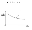
- FIG. 14 illustrates the relationship of the rate of change (G/ ⁇ ⁇ AP ) of the acceleration G to the amount ⁇ ⁇ AP of depression of the acceleration pedal for acceleration from a cruise.
- the curve C in FIG. 14 represents the rate of change (G/ ⁇ ⁇ AP ) of the acceleration which is required to make the acceleration as felt by the driver match the depression of the accelerator pedal.
- the rate of change (G/ ⁇ AP ) of the acceleration is required to be larger when the amount ⁇ ⁇ AP of depression of the accelerator pedal is small than when the amount ⁇ ⁇ AP of depression of the accelerator pedal is large. Therefore, if the actual acceleration is controlled so as to vary linearly with respect to the depression of the accelerator pedal, then it is difficult to satisfy the demand from the driver for acceleration.
- the driver learns such a nonlinear relationship through experience. If the driver's learning is not enough, then the vehicle speed may get higher or lower than expected by the driver when the accelerator pedal is depressed as if the vehicle is running at a medium or high speed while the vehicle is actually running at a low speed. Consequently, the vehicle cannot run at a cruising speed demanded by the driver, but the driver may have to release or further depress the accelerator pedal after it has been depressed. For the above reasons, the conventional transmission control methods do not allow the driver to control the accelerator pedal with ease.
- GB-A-2154763 discloses a vehicle with an automatic transmission, in which a desired output torque is obtained from a map in Fig. 14 based on accelerator opening, and in which throttle control is based on the difference between the actual and desired torque, the transmission being controlled, for example, as in Fig. 8.
- a method of controlling an automatic transmission on a motor vehicle comprising the step of:
- cruising speeds of the motor vehicle vary linearly as the first indications vary. From this target acceleration map, a target acceleration is determined on the basis of the actual values of the first and second indications at the time, and the engine and the speed reduction ratio of the automatic transmission are controlled so that the target acceleration is achieved.
- the cruising speeds are those vehicle speeds at which the motor vehicle runs steadily, i.e., the acceleration is zero.
- the driver can control the accelerator pedal with ease at those cruising speeds.
- the target acceleration may increase as the amount of depression of the acceleration increases, at a rate which is greater when the amount of depression of the accelerator pedal is smaller.
- Such characteristics satisfy the demand from the driver for vehicle acceleration or deceleration, so that the driver is given a good acceleration feeling.
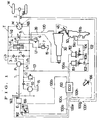
- FIG. 1 shows a hydraulic circuit of a continuously variable transmission which is to be controlled by a control method according to the present invention.
- the continuously variable transmission generally designated by the reference numeral T, has a fixed-displacement hydraulic pump P drivable by an engine E on a motor vehicle through an input shaft 1 and a variable-displacement hydraulic motor M having an output shaft 2 for driving road wheels W of the motor vehicle.
- the hydraulic pump P and the hydraulic motor M are hydraulically connected to each other through a closed hydraulic circuit including a first oil passage La interconnecting the outlet port of the pump P and the inlet port of the motor M and a second oil passage Lb interconnecting the inlet port of the pump P and the outlet port of the motor M.
- a charging pump 10 drivable by the engine 8 has an outlet port connected to the closed hydraulic circuit through a charging oil passage Lh having a check valve 11 and a third oil passage Lc having a pair of check valves 3.
- Working oil supplied from an oil sump 15 by the charging pump 10 and regulated in pressure by a charging pressure relief valve 12 is supplied through one of the check valves 3 to a lower-pressure one of the oil passages La, Lb.
- a fourth oil passage Ld having a shuttle valve 4 coupled to fifth and sixth oil passages Le, Lf having higher- and lower-pressure relief valves 6, 7 and connected to the oil sump 15.
- the shuttle valve 4 which comprises a two-port three-position directional control valve is operable in response to the difference between oil pressures in the first and second oil passages La, Lb for connecting a higher-pressure one of the first and second oil passages La, Lb to the fifth oil passage Le and the lower-pressure oil passage to the sixth oil passage Lf. Therefore, the oil pressure relieved from the higher-pressure oil passage is regulated by the higher-pressure relief valve 6, whereas the oil pressure relieved from the lower-pressure oil passage is regulated by the lower-pressure relief valve 7.
- a seventh oil passage Lg having a clutch valve 5 which comprises a variable restriction controlled by an opening control unit (not shown) for controlling the opening of the seventh oil passage Lg.
- the transmission of the drive power from the hydraulic pump P to the hydraulic motor M can be controlled through the control of the cross-sectional flow area in the clutch valve 5.
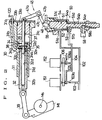
- An actuator for controlling the displacement of the hydraulic motor M to control the speed reduction ratio or transmission ratio of the continuously variable transmission T comprises a pair of first and second servounits 30, 50 mechanically operably coupled to each other by a lid mechanism 45.
- the hydraulic motor M comprises a swash-plate axial-piston motor whose displacement can be controlled by controlling the angle of the swash plate thereof.
- the higher-pressure working oil supplied from the closed hydraulic circuit of the continuously variable transmission T through the shuttle valve 4 to the fifth oil passage Le is introduced into the first servounit 30 through a high-pressure line 120 branched from the fifth oil passage Le.
- the first servounit 30 controls the swash plate angle of the hydraulic motor M under the higher-pressure wording oil thus introduced.
- the second servounit 50 controls operation of the first servounit 30 through the link mechanism 45 by which the second servounit 50 is operatively coupled to the first servounit 30.
- the first servounit 30 comprises a housing 31 having a port 31a connected to the high-pressure line 120, a piston member 32 slidably disposed in the housing 31, and a spool member 34 coaxially slidably disposed in the piston 32.
- the piston member 32 has a piston 32a on its righthand (as shown) end, and a cylindrical rod 32b extending coaxially from the piston 32a to the left (as shown).
- the piston 32a is positioned in a cylinder hole 31c defined in the housing 31 and divides the space of the cylinder hole 31c into left and right (as shown) cylinder chambers 35, 36.
- the rod 32b is slidably fitted in a rod hole 31d which is smaller in diameter than and extends coaxially from the cylinder hole 31c.
- the right cylinder chamber 36 is closed by a plug 33a and a cover 33b.
- the spool member 34 extends through the piston 32a, the right cylinder chamber 36, the plug 33a, and the cover 33b.
- the left cylinder chamber 35 communicates with the high-pressure line 120 through an oil passage 31b defined in the housing 31.
- the piston member 32 can therefore be moved to the right under the oil pressure introduced from the high-pressure line 120 into the left cylinder chamber 35.
- the spool member 34 has on its distal end a land 34a closely fitted in a spool hole 32d defined coaxially in the rod 32b.
- the spool member 34 also has a recess 34b defined on the righthand side of the land 34a by a pair of diametrically opposite cutouts, the recess 34b having a predetermined axial dimension.
- a retaining ring 37 is fitted over the spool member 34 on the righthand side of the recess 34b. The spool member 34 is prevented from removal from the piston member 32 by the retaining ring 37 upon engagement with another retaining ring 38 locked in an inner peripheral surface of the piston member 32.
- the piston member 32 has defined therein a discharge passage 32e for opening the right cylinder chamber 36 into an oil sump (not shown) through the spool hole 32d upon rightward movement of the spool member 34, and a communication passage 32c for bringing the right cylinder chamber 36 into communication with the left cylinder chamber 35 through the recess 34b upon leftward movement of the spool member 34.
- the recess 34b opens the communication passage 32c into the right cylinder chamber 36, and the land 34a closes the discharge chamber 32e.
- the high-pressure oil from the high-pressure line 120 then acts in both the left and right cylinder chambers 35, 36. Since the piston 32a has different pressure-bearing surface areas on its axially opposite sides, i.e., the righthand pressure-bearing surface area is greater than the lefthand pressure-bearing surface area, the piston 32 is moved to the left in follow-up coaction with the spool member 34.
- the piston member 32 is moved in follow-up unison with the spool member 34 under the pressure of the oil supplied from the high-pressure line 120.
- the piston member 32 then causes a link 39 coupled thereto to turn the swash plate Mt of the hydraulic motor M about a shaft Ms for thereby varying the displacement of the hydraulic motor M.
- the spool member 34 is operatively coupled to the second servounit 50 by the link mechanism 45.
- the link mechanism 45 comprises a first link 47 rotatable about a shaft 47c and having two substantially perpendicular arms 47a, 47b, and a second link 48 joined by a pin to the lower distal end of the arm 47b of the first link 47.
- the upper end of the arm 47a is connected by a pin to the righthand end of the spool member 34 of the first servounit 30.
- the lower end of the second link 48 is coupled by a pin to a vertical (as shown) spool member 54 of the second servounit 50. Consequently, vertical movement of the spool member 54 of the second servounit 50 causes the spool member 34 of the first servounit 30 to move to the left or right.
- the second servounit 50 has a housing 51 having two ports 51a, 51b to which two oil pressure lines 102, 104 are connected, respectively, and the spool member 54 is vertically slidably disposed in the housing 51.
- the spool member 54 comprises a piston 54a and a rod 54b extending coaxially downwardly from the piston 54a.
- the piston 54a is slidably fitted in a cylinder hole 51c defined vertically in the housing 51.
- the cylinder hole 51c is closed by a cover 55, defining a cylinder chamber therein which is divided by the piston 54a into upper and lower cylinder chambers 52, 53.
- the rod 54b is slidably fitted in a rod hole 51d which is defined coaxially in the housing 51 and extends downwardly from the cylinder hole 51c.
- the rod 54b has a recess 54e defined in a peripheral surface and having a tapered surface.
- a top position detector switch 58 has a spool 58a projecting into the recess 54e. When the spool member 54 moves upwardly, the spool 58a is lifted in a direction away from the rod 54b as the tip end of the spool 58a slides up the tapered surface. Therefore, the top position detector switch 58 can detect when the transmission ratio of the hydraulic motor M is minimum.
- the upper and lower cylinder chambers 52, 53 defined by the piston 54a communicate respectively with the oil pressure lines 102, 104 through the ports 51a, 51b.
- the spool member 54 is moved upwardly or downwardly depending on the magnitude of an oil pressure applied to the piston 54a, the oil pressure being determined by the pressure of working oil supplied through the lines 102, 104 and the pressure-bearing surface areas of the piston 54a in the cylinder chambers 52, 53.
- the vertical movement of the spool member 54 is transmitted through the link mechanism 45 to the spool member 34 of the first servounit 30 thereby to move the spool member 34 to the left or right.
- the movement of the spool member 34 of the first servounit 30 can be controlled to move the piston member 32 for thereby controlling the swash plate angle of the hydraulic motor M, so that the displacement of the motor M will be controlled to control the transmission ratio or speed reduction ratio.
- the piston member 32 of the first servounit 30 is moved to the right to reduce the swash plate angle of the hydraulic motor M for reducing the displacement of the motor M and hence the speed reduction ratio.
- Oil pressure which is supplied to the upper cylinder chamber 52 through the port 51a from the oil pressure line 102 is introduced from the charging pump 10, while being regulated by the charging pressure relief valve 12, through an oil pressure line 101.
- Oil pressure which is supplied to the lower cylinder chamber 53 through the port 51b is introduced from an oil pressure line 103 branched from the oil pressure line 102 and having an orifice 103a, while being regulated by two duty-ratio-controlled solenoid-operated valves 151, 152, through an oil pressure line 104.
- the solenoid-operated valve 151 is opened and closed depending on a given duty ratio to control the rate of flow of working oil from the oil pressure line 103 to the oil pressure line 104.
- the solenoid-operated valve 152 is connected between an oil pressure line 105 branching from the oil pressure line 104 and an oil pressure line 106 connected to a drain through an orifice 106a.
- the solenoid-operated valve 152 is opened and closed depending on a given duty ratio to control the rate of flow of working oil from the oil pressure line 104 to the drain.
- the upper cylinder chamber 52 is supplied through the oil pressure line 102 with the charging oil pressure which has been regulated by the charging pressure relief valve 12.
- the oil pressure line 104 supplies the lower cylinder chamber 53 with an oil pressure which is made lower than the charging oil pressure by the two solenoid-operated valves 151, 152. Since the pressure-bearing surface area of the upper cylinder chamber 52 is smaller than that of the lower cylinder chamber 53, the forces acting on the opposite sides of the spool member 54 under the oil pressures in the upper and lower cylinder chambers 52, 53 are brought into equilibrium when the oil pressure Pu in the upper cylinder chamber 52 is higher than a certain level Pl of the oil pressure in the lower cylinder chamber 53 (Pu > Pl).
- the spool member 54 is moved upwardly to reduce the swash plate angle of the hydraulic motor M for thereby reducing the speed reducing ratio, and by controlling the solenoid-operated valves 151, 152 to reduce the oil pressure supplied to the lower cylinder chamber 53 below the pressure level Pl, the spool member 54 is moved downwardly to increase the swash plate angle of the hydraulic motor M for thereby increasing the speed reducing ratio.
- the solenoid-operated valves 151, 152 are controlled by a control signal fed from a controller 100 over a signal line 100a.
- the controller 100 is supplied with a throttle valve opening signal ⁇ th applied from an engine throttle valve opening sensor 161 over a signal line 100c, an intake vacuum signal P B delivered over a signal line 100d from a vacuum sensor 162 which detects the intake vacuum in an intake manifold, an engine rotational speed signal Ne delivered from an engine rotational speed sensor 163 over a signal line 100e, a vehicle speed signal V delivered over a signal line 100f from a vehicle speed sensor 164 which detects the vehicle speed based on the rotational speed of the output shaft 2, a swash plate angle signal ⁇ tr delivered over a signal line 100g from a swash plate angle sensor 165 which detects the swash plate angle of the hydraulic motor M, and an accelerator opening signal ⁇ AP delivered from an accelerator pedal movement sensor 166 over a signal line 100h.
- the controller 100 produces a control signal based on the above input signals applied thereto and applies the control signal to the solenoid-operated valves 151, 152 to achieve desired running performance of the
- the controller 100 also sends a control signal over a line 100b to a throttle valve actuator 155 which controls the opening of the throttle valve.
- the controller 100 produces this control signal based on the input signals for controlling operation of the throttle valve actuator 155 to achieve desired running performance of the motor vehicle.
- the predicted acceleration Ga is derived from the equations (4) through (7) given below.
- the predicted acceleration Ga can be calculated from the reserve power Pa of the engine E, and the reserve power Pa is determined according to the equation (5).
- C 1 is a constant.
- the terms of the above equation can be weighted by varying the constant C 1 , C 2 .
- the target rate dNeo/dt of change of the engine rotational speed is determined by calculating the difference ⁇ Ne between the target engine rotational speed Neo which is set according to an indication of the driver's intention for acceleration or deceleration, such as the amount of depression of the accelerator pedal, for example, and the actual engine rotational speed Ne, and finding a suitable value from a table which contains predetermined target rates dNeo/dt that correspond to the speed differences ⁇ Ne in view of vehicle running conditions as felt by the driver and fuel consumption.
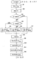
- FIG. 4 shows a control block diagram for effecting a throttle valve control process based on the flowchart of FIG. 3
- FIG. 5 shows a control block diagram for effecting a speed reduction ratio control process based on the flowchart of FIG. 3.
- Step S3, S4 determine whether a shift range is an L range, an S range, or a D range, and steps S5, S6, S7 select a Go map corresponding to the determined shift map.
- the shift range means a gear range which is established depending on the position of a shift lever which is manipulated by the driver.
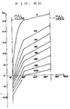
- the Go map for the D range is shown in FIG. 6A, the Go map for the S range in FIG. 6B, and the Go map for the L range in FIG. 6C.
- a target acceleration Go to be reached is determined from the accelerator opening ⁇ AP and the vehicle speed V in a step S8, a block B1 (FIG. 4), and a block B29 (FIG. 5).
- FIGS. 6A through 6C there are preset maps representing curves indicating desired target accelerations Go to be reached for respective vehicle speeds, the target accelerations Go being plotted against the accelerator openings ⁇ AP .
- a target acceleration Go to be reached which corresponds to the accelerator opening ⁇ AP and the vehicle speed V that are thus read is read from the target acceleration maps, so that the target acceleration for obtaining a desired driver's acceleration feeling corresponding to the accelerator pedal depression at the vehicle speed can be achieved.
- the numerical values allotted to the respective curves in the target acceleration maps indicate vehicle speeds in the unit of km/h.
- the curves indicative of the target accelerations corresponding to the vehicle speeds are spaced at substantially equal intervals.
- the distances between the curves at cruising speeds i.e., vehicle speeds at which the target acceleration is zero
- the cruising speed is proportional to the accelerator opening ⁇ AP .
- the change in the accelerator opening at the time the cruising speed varies from 0 km/h to 20 km/h is the same as the change in the accelerator opening at the time the cruising speed varies from 20 km/h to 40 km/h.
- the gradient of the curves corresponding to the vehicle speeds is larger as the accelerator opening ⁇ AP is smaller. Specifically, when the accelerator opening ⁇ AP is smaller, the rate at which the target acceleration increases upon depression of the accelerator pedal is larger, and when the accelerator opening ⁇ AP is larger, the rate is smaller.
- the acceleration as felt by the driver upon depression of the accelerator pedal tends to be small.
- the rate at which the target acceleration increases is large, allowing the driver to have an acceleration feeling which matches his intention for acceleration.
- the graphs shown in FIGS. 6A through 6C contain regions where the target acceleration Go is negative. In those regions, there are established target decelerations to be reached when the accelerator pedal is released while the motor vehicle is running, applying an engine brake to decelerate the motor vehicle.
- a reserve power Pa of the engine at the present time is calculated according to the equation (5) above.
- an actual engine output power Pea is determined on the basis of the intake vacuum pressure P B and the engine rotational speed Ne in a block B11
- a transfer efficiency ⁇ for the engine output power is determined on the basis of the intake vacuum pressure P B , the coolant temperature T W , the swash plate angle ⁇ tr, and the clutch opening ⁇ CL in a block B12
- a running load P L i.e., the sum of a road resistance R ⁇ and an air resistance Ra, is determined on the basis of the vehicle speed V in a block B13.
- the reserve power Pa can be determined using the equation (5).
- the engine output power Pea is corrected by the transfer efficiency ⁇ .
- the engine output power Pea is determined in a block B24, the transfer efficiency ⁇ is determined in a block B28, and an engine output power Pe which is actually transferred is calculated in a step B25. Then, the reserve power is determined by subtracting the load P L which has been determined in a block B33 from the engine output power Pe.
- a calculative acceleration G CAL corresponding to the reserve power of the engine thus determined is calculated in a step S9, a block B15, and a block B30.
- a predicted acceleration is calculated using the reserve power Pa according to the equation (7), and the predicted acceleration thus determined is the calculative acceleration G CAL .
- a corrective value dGon/dt for the calculative acceleration G CAL which is necessary to vary the present acceleration (calculative acceleration G CAL ) up to the target acceleration Go to be reached along a desired characteristic curve, is calculated on the basis of the acceleration difference ⁇ G in a step S11, a block B3, and a block B31.
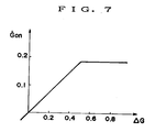
- the corrective value dGon/dt is determined, for example, using a map or graph as shown in FIG. 7 which contains calculated corrective values corresponding to different values of the acceleration difference ⁇ G. Therefore, the desired corrective value dGon/dt corresponding to the present acceleration difference ⁇ G calculated in the step S10 can be found in the graph of FIG. 7 according to the solid-line curve therein.
- This present target acceleration Gon is an acceleration which is required at the present time to vary the present acceleration G CAL up to the target acceleration Go to be reached along the desired characteristic curve.
- the throttle valve opening and the speed reduction ratio of the transmission are controlled in order to obtain the target acceleration Gon.
- the engine rotational speed Ne is read in a step S13, and then a target engine rotational speed Neo which corresponds to the accelerator opening ⁇ AP and the vehicle speed V that have already been read in is calculated in a step S14 and a block B21.
- values of the target engine rotational speed Neo are preset for the vehicle speeds V 1 through V 5 and plotted against values of the accelerator opening ⁇ AP . Therefore, the target engine rotational speed Neo is determined which corresponds to the present accelerator opening ⁇ AP and vehicle speed V that have been read in the steps S1, S2.
- the target rate dNeo/dt is determined from the graph of FIG. 9, for example, which contains preset rates of change of the engine rotational speed such that the engine rotational speed will vary along a desired characteristic curve depending on the rotational speed difference ⁇ Ne.
- a target intake vacuum P Bon which is required to vary the present engine horsepower P SRL up to the target engine horsepower Pson at the engine rotational speed Ne at this time, is calculated in a step S19 and a block B6.
- a map (FIG. 10) containing values of the engine horsepower Pe depending on values of the engine intake vacuum pressure P B and values of the engine rotational speed Ne may be employed, and the target intake vacuum pressure P Bon to the target engine horsepower Pson and the engine rotational speed Ne may be determined from the map.
- the throttle valve of the engine may then be controlled in order to achieve the target intake vacuum P Bon which is thus obtained.
- the throttle valve opening is reduced smaller than a predetermined opening and the intake vacuum pressure becomes higher than a predetermined level P BG , the engine horsepower is very small, and the throttle valve opening control is not effective enough to adjust the engine horsepower.
- a step S20 determines whether the target intake vacuum pressure P Bon is lower than the predetermined value P BG or not, so that different control modes will be performed if P Bon ⁇ P BG and if P Bon ⁇ P BG .
- the engine throttle valve is controlled so that the target intake vacuum P Bon will be obtained in a step S21.
- the engine throttle valve control process is shown in blocks B7 through B10 of FIG. 4.
- the difference ⁇ P B between the target intake vacuum pressure P Bon and the actual intake vacuum pressure P B is determined, and the difference ⁇ P B is multiplied by a coefficient ⁇ ⁇ TPB , thus obtaining a basic throttle change value d TH in the block B8.
- the coefficient ⁇ ⁇ TPB is a coefficient which represents a change in the throttle opening which is required to effect a unit change in the intake vacuum pressure.
- a corrective coefficient K PBO for an operation gain of the throttle valve actuator 155 with respect to the target intake vacuum pressure P Bon is determined in the block B7.
- the operation gain is corrected because the amount of operation of the throttle valve actuator and the intake vacuum pressure are not proportionally related to each other.
- the corrective coefficient K PBO is determined by reading a gain corresponding to the target intake vacuum pressure P Bon from the predetermined relationship between intake vacuum pressures P B and operation gains of the throttle valve actuator 155.
- the intake vacuum pressure difference d TH is multiplied by the corrective coefficient K PBO to determine an amount of operation ⁇ TH of the throttle valve actuator 155 which is required to vary the intake vacuum pressure by the difference d TH in the block B9.
- the throttle valve actuator 155 is now operated by the amount of operation ⁇ TH thereby to control the throttle valve. Now, an engine horsepower which is suitable and required to reach the target acceleration Gon can be generated.
- control goes from the step S20 to a step S24 in which the engine throttle valve is controlled so that the intake vacuum pressure P B is equalized to the predetermined value P BG (constant). Since the engine horsepower cannot be adjusted by the throttle valve control at this time, the transmission control is effected to make up for the engine horsepower adjustment.
- the duty ratio of the solenoid-operated valves 151, 152 is determined in order to reach the rate di/dt of change in the speed reduction ratio, and the solenoid-operated valves 151, 152 are controlled on the basis of the duty ratio, thereby controlling the speed reduction ratio.
- the motor vehicle can also be accelerated (or decelerated) according to the target acceleration Gon.
- the above flow or control sequence is cyclically repeated every preset period of time (e.g., every 10 ms) for continuously controlling the speed reduction ratio along a desired acceleration (or deceleration) characteristic curve. If the speed reduction ratio is controlled through the duty ratio control of the solenoid-operated valves as with the illustrated embodiment, then a control signal for the solenoid-operated valves is issued every 100 ms, for example, even though the control sequence is repeated every 10 ms, because the mechanical parts of the solenoid-operated valves have slow responses.
- the engine throttle opening may instead be used as such an indication.
- control method of the present invention has been described as being applied to a continuously variable transmission which comprises a hydraulic pump and hydraulic motor.
- a continuously variable transmission which comprises a hydraulic pump and hydraulic motor.
- principles of the present invention are also applicable to any of various other types of continuously variable transmission.
- the automatic transmission which can be controlled by the method of the present invention may be either a continuously variable transmission which is automatically controlled as described above or a gear-type automatic transmission which has a plurality of discrete gear positions. Such a gear-type automatic transmission can also be controlled according to the control method of the present invention.
Landscapes
- Engineering & Computer Science (AREA)
- Mechanical Engineering (AREA)
- Chemical & Material Sciences (AREA)
- Combustion & Propulsion (AREA)
- General Engineering & Computer Science (AREA)
- Transportation (AREA)
- Automation & Control Theory (AREA)
- Control Of Fluid Gearings (AREA)
- Control Of Transmission Device (AREA)
- Control Of Driving Devices And Active Controlling Of Vehicle (AREA)
Claims (15)
- Verfahren zum Steuern/Regeln eines automatischen Getriebes (T) an einem Kraftfahrzeug, umfassend die Schritte:Erfassen eines ersten Merkmals (θAP), das die Absicht des Fahrers nach Beschleunigung oder Verzögerung des Kraftfahrzeugs darstellt, und eines zweiten Merkmals (V), das eine Geschwindigkeit des Kraftfahrzeugs darstellt;Bestimmen einer zu erreichenden Sollbeschleunigung (GO), die dem ersten (θAP) und dem zweiten (V) Merkmal entspricht, aus einem Sollbeschleunigungskennfeld, das Sollbeschleunigungen (GO) enthält, die ersten Merkmalen (θAP), die die Absicht des Fahrers nach Beschleunigung oder Verzögerung darstellen, und zweiten Merkmalen (V), die Geschwindigkeiten des Kraftfahrzeugs darstellen, entsprechen;und Steuern/Regeln der Übersetzung des automatischen Getriebes und der Fahrzeugmaschine derart, daß die Sollbeschleunigung erreicht wird;dadurch gekennzeichnet,
daß das Sollbeschleunigungskennfeld derart ausgebildet ist, daß sich Reisegeschwindigkeiten (V) des Kraftfahrzeugs in dem Sollbeschleunigungskennfeld mit Änderung der ersten Merkmale (θAP) linear ändern. - Verfahren nach Anspruch 1, bei dem das Sollbeschleunigungskennfeld derart ausgebildet ist, daß, wenn jedes der zweiten Merkmale (V) konstant ist, jede der Sollbeschleunigungen (GO) mit Zunahme des ersten Merkmals (θAP) für positive Werte der Beschleunigung mit einer Rate zunimmt, die bei niedrigen Werten des ersten Merkmals (θAP) größer als bei höheren Werten ist.
- Verfahren nach Anspruch 1 oder 2, bei dem das Sollbeschleunigungskennfeld eine Mehrzahl von Kennfeldern enthält, die jeweils einer Mehrzahl von Schaltbereichen entsprechen, und wobei eines der Kennfelder, das dem gegenwärtigen Schaltbereich entspricht, zur Bestimmung der Sollbeschleunigung verwendet wird.
- Verfahren nach einem der vorhergehenden Ansprüche, bei dem das erste Merkmal einem Niederdrückbetrag (θAP) eines Gaspedals entspricht.
- Verfahren nach einem der vorhergehenden Ansprüche, bei dem das automatische Getriebe ein stufenlos verstellbares Getriebe umfaßt.
- Verfahren nach Anspruch 5, bei dem das stufenlos verstellbare Getriebe eine von der Maschine antreibbare Hydraulikpumpe (P) und einen durch von der Hydraulikpumpe zugeführten Öldruck antreibbaren Hydraulikmotor (M) umfaßt, wobei wenigstens ein Element von Hydraulikpumpe und Hydraulikmotor vom Typ variabler Verdrängung ist, wobei das Verfahren ferner den Schritt umfaßt:
Steuern/Reglen des stufenlos verstellbaren Getriebes durch Steuern/Regeln der variablen Verdrängung der Hydraulikpumpe oder des Hydraulikmotors. - Verfahren nach einem der Ansprüche 1 bis 4, bei dem das automatische Getriebe ein Stufengetriebe mit einer Mehrzahl getrennter Gangstellungen umfaßt.
- Verfahren nach einem der vorhergehenden Ansprüche, das ferner die Schritte umfaßt:Berechnen einer gegenwärtigen Rechen-Beschleunigung GCAL aufgrund einer Restleistung Pa der Maschine, die das automatische Getriebe antreibt;Einrichten einer gegenwärtigen Sollbeschleunigung Gon, die gegenwärtig zum Ändern der Istbeschleunigung zu der Sollbeschleunigung GO entlang einer gewünschten Kennlinie erforderlich ist, entsprechend der Differenz ΔG (= GO - GCAL) zwischen der Sollbeschleunigung GO und der Rechen-Beschleunigung GCAL.
- Verfahren nach Anspruch 8, in dem die Rechen-Beschleunigung GCAL aufgrund der Restleistung Pa der Maschine nach der Gleichung bestimmt wird:
 g = die Erdbeschleunigung;W = das Gesamtgewicht des Kraftfahrzeugs;ΔW = die Äquivalenzmasse der drehenden Teile des Antriebssystems des Kraftfahrzeugs; undV = die Geschwindigkeit des Kraftfahrzeugs.
 - Verfahren nach Anspruch 8 oder 9, das ferner die Schritte umfaßt:
Steuern/Regeln eines Drosselventils (161) der Maschine sowie Steuern/Regeln der Übersetzung des automatischen Getriebes derart, daß die gegenwärtige Sollbeschleunigung erreicht wird. - Verfahren nach Anspruch 10, bei dem das Drosselventil durch ein Drosselventilstellglied (155) gesteuert wird, das in Antwort auf ein Steuersignal von einer Steuereinrichtung betreibbar ist.
- Verfahren nach Anspruch 10 oder 11, das ferner die Schritte umfaßt:Berechnen einer gegenwärtigen Maschinenpferdestärke PSRL aus einem Maschineneinlaßunterdruck PB und einer Maschinendrehzahl Ne;Bestimmen einer Sollmaschinenpferdestärke Pson, die zum Erhalt der gegenwärtigen Sollbeschleunigung Gon erforderlich ist, nach der Gleichung:
 W = das Gesamtgewicht des Kraftfahrzeugs;ΔW = die Äquivalenzmasse der drehenden Teile des Antriebssystems des Kraftfahrzeugs; undV = die Geschwindigkeit des Kraftfahrzeugs;Berechnen eines Sollmaschineneinlaßunterdrucks PBon, der zum Ändern der Istmaschinenpferdestärke PSRL bis zur Sollmaschinenpferdestärke Pson bei der Maschinendrehzahl Ne erforderlich ist;falls der Solleinlaßunterdruck PBon niedriger als ein vorbestimmter Wert PBG ist, Steuern/Reglen des Drosselventils der Maschine derart, daß der Solleinlaßunterdruck PBon erhalten wird; undfalls der Solleinlaßunterdruck PBon gleich oder höher als der vorbestimmte Wert PBG ist, Steuern/Regeln des Drosselventils der Maschine derart, daß der Einlaßunterdruck den vorbestimmten Wert PBG einnimmt.
 - Verfahren nach Anspruch 12, bei dem ein Kennfeld, das die Korrelation zwischen dem Maschineneinlaßunterdruck PB, der Maschinendrehzahl Ne und der Maschinenpferdestärke Pe bezeichnet, eingerichtet wird und der Solleinlaßunterdruck PBon aus dem Kennfeld bestimmt wird.
- Verfahren nach Anspruch 12 oder 13, das ferner die Schritte umfaßt:falls der Solleinlaßunterdruck PBon unter dem vorbestimmten Wert PBG liegt, Berechnen einer Sollmaschinendrehzahl Neo entsprechend dem Merkmal der Absicht des Fahrers nach Beschleunigung oder Verzögerung und dem Merkmal der Geschwindigkeit des Kraftfahrzeugs, und ferner Berechnen der Differenz ΔNe (= Neo - Ne) zwischen der Sollmaschinendrehzahl Neo und der Istmaschinendrehzahl Ne;Berechnen der Solländerungsrate dNeo/dt der Maschinendrehzahl, die gegenwärtig erforderlich ist, um die Istmaschinendrehzahl Ne bis zur Sollmaschinendrehzahl Neo entlang einer gewünschten Kennlinie zu ändern, aufgrund der Differenz ΔNe;Bestimmen einer Komponente diN/dt, die der Sollrate dNeo/dt entspricht, nach der Gleichung:
 Bestimmen einer Komponente diP/dt, die einer vorhergesagten Beschleunigung entspricht, unter Verwendung der Restpferdestärke Pa der Maschine, nach der Gleichung:
 Addieren der Komponenten diN/dt und diP/dt, um hierdurch eine Änderungsrate di/dt des Drehzahlminderungsverhältnisses des automatischen Getriebes zu bestimmen; undSteuern/Regeln des Drehzahlminderungsverhältnisses des automatischen Getriebes derart, daß die Änderungsrate (di/dt) des Drehzahlminderungsverhältisses erreicht wird.
 - Verfahren nach Anspruch 12, 13 oder 14, das ferner die Schritte umfaßt:falls der Solleinlaßunterdruck PBon gleich oder höher als der vorbestimmte Wert PBG ist, Berechnen einer Sollmaschinendrehzahl Neo entsprechend dem Merkmal der Absicht des Fahrers nach Beschleunigung oder Verzögerung und dem Merkmal der Geschwindigkeit des Kraftfahrzeugs, und ferner Berechnen der Differenz ΔNe (= Neo - Ne) zwischen der Sollmaschinendrehzahl Neo und der Istmaschinendrehzahl Ne;Berechnen einer Solländerungsrate dNeo/dt der Maschinendrehzahl, die gegenwärtig zum Ändern der Istmaschinendrehzahl Ne bis zur Sollmaschinendrehzahl Neo entlang einer gewünschten Kennlinie erforderlich ist, aufgrund der Differenz ΔNe;Bestimmen einer Komponente diN/dt, die der Sollrate dNeo/dt entspricht, nach der Gleichung:
 Bestimmen einer Komponente diP/dt, die einer vorhergesagten Beschleunigung entspricht, unter Verwendung der Restpferdestärke Pa der Maschine, nach der Gleichung:
 Bestimmen einer Korrekturkomponente diG/dt nach der Gleichung:
 Addieren der Komponenten diN/dt, diP/dt und diG/dt, um hierdurch eine Änderungsrate di/dt des Drehzahlminderungsverhältnisses des automatischen Getriebes zu bestimmen; undSteuern/Regeln des Drehzahlminderungsverhältnisses des automatischen Getriebes derart, daß die Änderungsrate di/dt des Drehzahlminderungsverhältnisses erreicht wird.
Applications Claiming Priority (2)
| Application Number | Priority Date | Filing Date | Title |
|---|---|---|---|
| JP268692/89 | 1989-10-16 | ||
| JP1268692A JP2568923B2 (ja) | 1989-10-16 | 1989-10-16 | 無段変速機の制御方法 |
Publications (3)
| Publication Number | Publication Date |
|---|---|
| EP0424088A2 EP0424088A2 (de) | 1991-04-24 |
| EP0424088A3 EP0424088A3 (en) | 1991-10-09 |
| EP0424088B1 true EP0424088B1 (de) | 1996-09-11 |
Family
ID=17462058
Family Applications (1)
| Application Number | Title | Priority Date | Filing Date |
|---|---|---|---|
| EP90311317A Expired - Lifetime EP0424088B1 (de) | 1989-10-16 | 1990-10-16 | Steuerungssystem für ein automatisches Getriebe |
Country Status (4)
| Country | Link |
|---|---|
| US (1) | US5754428A (de) |
| EP (1) | EP0424088B1 (de) |
| JP (1) | JP2568923B2 (de) |
| DE (1) | DE69028475T2 (de) |
Families Citing this family (29)
| Publication number | Priority date | Publication date | Assignee | Title |
|---|---|---|---|---|
| JP2641004B2 (ja) * | 1992-01-21 | 1997-08-13 | 本田技研工業株式会社 | 車両用無段変速機における加速および減速スキップ変速制御方法 |
| JP3369594B2 (ja) * | 1992-05-29 | 2003-01-20 | 本田技研工業株式会社 | 電気走行車 |
| JPH08135789A (ja) * | 1994-11-09 | 1996-05-31 | Komatsu Ltd | 車両の油圧式駆動装置の変速装置およびその変速制御方法 |
| DE19611804A1 (de) * | 1996-03-26 | 1997-10-02 | Bosch Gmbh Robert | Vorrichtung zur Einstellung einer Übersetzung eines kontinuierlich verstellbaren Getriebes |
| EP0967107B1 (de) * | 1998-06-25 | 2001-09-19 | ZF FRIEDRICHSHAFEN Aktiengesellschaft | Verfahren zum Steuern einer Fahrzeugantriebseinheit mit stufenlos verstellbarem Getriebe |
| AT4125U1 (de) * | 1999-04-28 | 2001-02-26 | Case Steyr Landmaschinentechni | Vorrichtung und verfahren zum verändern der ist-geschwindigkeit eines arbeitsfahrzeuges mit stufenlosgetriebe und tempomatfunktion |
| JP2000320658A (ja) * | 1999-05-14 | 2000-11-24 | Honda Motor Co Ltd | 車両の速度制御装置 |
| JP4191362B2 (ja) * | 2000-03-31 | 2008-12-03 | 本田技研工業株式会社 | 無段変速機の制御方法 |
| US6553301B1 (en) * | 2000-05-19 | 2003-04-22 | General Motors Corporation | System and method of providing optimal fuel economy for automobiles |
| JP3680746B2 (ja) * | 2001-03-09 | 2005-08-10 | 日産自動車株式会社 | 変速比無限大無段変速機の制御装置 |
| JP3580260B2 (ja) * | 2001-03-01 | 2004-10-20 | 日産自動車株式会社 | 車両の制御装置 |
| JP2003074682A (ja) * | 2001-08-31 | 2003-03-12 | Fuji Heavy Ind Ltd | 無段変速機の制御装置 |
| EP1442240A1 (de) * | 2001-10-12 | 2004-08-04 | Clark Equipment Company | Betrieb einer mit rädern versehenen arbeitsmaschine |
| WO2004029435A1 (ja) * | 2002-09-26 | 2004-04-08 | Hitachi Construction Machinery Co., Ltd. | 建設機械の原動機制御装置 |
| DE10360641B4 (de) * | 2003-12-23 | 2017-01-12 | Jochen Strenkert | Vorrichtung mit einer Einheit zum Betätigen eines stufenlosen Kraftfahrzeuggetriebes |
| JP2006007819A (ja) * | 2004-06-22 | 2006-01-12 | Kanzaki Kokyukoki Mfg Co Ltd | 作業車両の速度制御方法 |
| JP4289276B2 (ja) * | 2004-10-25 | 2009-07-01 | トヨタ自動車株式会社 | 車両の制御装置 |
| JP4369403B2 (ja) * | 2005-07-05 | 2009-11-18 | 株式会社豊田中央研究所 | 加速感評価装置及び車両制御装置 |
| DE102006036317A1 (de) * | 2006-06-28 | 2008-01-03 | Brueninghaus Hydromatik Gmbh | Verfahren zur Steuerung eines Übersetzungsverhältnisses |
| EP1972836B1 (de) * | 2007-03-20 | 2012-12-26 | Yamaha Hatsudoki Kabushiki Kaisha | Elektronisch geregeltes, stufenlos verstellbares Getriebe |
| US7798277B2 (en) * | 2007-05-31 | 2010-09-21 | Caterpillar Inc | Machine retarder |
| JP4818337B2 (ja) * | 2008-09-17 | 2011-11-16 | 本田技研工業株式会社 | 車両の制御装置 |
| SE535204C2 (sv) * | 2009-12-17 | 2012-05-22 | Scania Cv Ab | Metod för bestämning av drivkraftkapacitet hos ett motorfordon |
| JP6222194B2 (ja) * | 2015-03-17 | 2017-11-01 | トヨタ自動車株式会社 | 駆動力制御装置 |
| JP6229701B2 (ja) * | 2015-09-18 | 2017-11-15 | トヨタ自動車株式会社 | 駆動力制御装置 |
| JP6229702B2 (ja) * | 2015-09-18 | 2017-11-15 | トヨタ自動車株式会社 | 駆動力制御装置 |
| JP6380311B2 (ja) * | 2015-09-18 | 2018-08-29 | トヨタ自動車株式会社 | 駆動力制御装置 |
| US10183684B2 (en) * | 2016-03-31 | 2019-01-22 | General Electric Company | Multiple vehicle control system |
| US12180683B2 (en) | 2017-06-27 | 2024-12-31 | Komatsu Ltd. | Work vehicle and control method for work vehicle |
Family Cites Families (18)
| Publication number | Priority date | Publication date | Assignee | Title |
|---|---|---|---|---|
| FR2466367A1 (fr) * | 1979-10-01 | 1981-04-10 | Renault | Procede de regulation d'un groupe motopropulseur et dispositif permettant sa mise en oeuvre |
| US4389910A (en) * | 1981-02-17 | 1983-06-28 | General Motors Corporation | Motor vehicle power control means |
| EP0092227B1 (de) * | 1982-04-19 | 1988-07-27 | Nissan Motor Co., Ltd. | Verfahren zum Verstellen des Übersetzungsverhältnisses eines stufenlosen Getriebes unter Anpassung der Beschleunigung |
| JPS5981230A (ja) * | 1982-10-30 | 1984-05-10 | Isuzu Motors Ltd | 電子制御式トランスミツシヨンの変速制御方式 |
| DE3467127D1 (en) * | 1983-03-11 | 1987-12-10 | Nissan Motor | Control system and control method for a vehicle |
| JPS6011758A (ja) * | 1983-06-30 | 1985-01-22 | Isuzu Motors Ltd | 自動変速機の変速制御法 |
| JPS60164632A (ja) * | 1984-02-07 | 1985-08-27 | Nissan Motor Co Ltd | 自動車の電子制御装置 |
| JPS60175857A (ja) * | 1984-02-20 | 1985-09-10 | Diesel Kiki Co Ltd | 車輛用自動変速制御装置 |
| JPS6141631A (ja) * | 1984-08-03 | 1986-02-28 | Nissan Motor Co Ltd | エンジン・無段変速機の制御装置 |
| JPS61112852A (ja) * | 1984-11-08 | 1986-05-30 | Diesel Kiki Co Ltd | 車輛用自動変速装置 |
| JPH064389B2 (ja) * | 1986-04-01 | 1994-01-19 | マツダ株式会社 | 自動車の定速走行制御装置 |
| JPH0721305B2 (ja) * | 1986-08-19 | 1995-03-08 | 本田技研工業株式会社 | 車両用無段変速機の変速制御装置 |
| JP2613037B2 (ja) * | 1987-01-06 | 1997-05-21 | トヨタ自動車株式会社 | 車両用無段変速機の制御方法 |
| JPH0771899B2 (ja) * | 1987-07-02 | 1995-08-02 | 三菱電機株式会社 | 車両用定速走行装置 |
| JPH01108464A (ja) * | 1987-10-20 | 1989-04-25 | Honda Motor Co Ltd | 車両用無段変速機の変速制御方法 |
| JP2882528B2 (ja) * | 1988-07-20 | 1999-04-12 | 本田技研工業株式会社 | 無段変速機のスロットル制御付き変速制御方法 |
| JPH0293163A (ja) * | 1988-09-30 | 1990-04-03 | Diesel Kiki Co Ltd | 車輌用自動変速装置 |
| JPH0686193B2 (ja) * | 1989-03-22 | 1994-11-02 | 本田技研工業株式会社 | スロットル制御付き無段変速機変速制御方法 |
-
1989
- 1989-10-16 JP JP1268692A patent/JP2568923B2/ja not_active Expired - Fee Related
-
1990
- 1990-10-10 US US07/595,394 patent/US5754428A/en not_active Expired - Fee Related
- 1990-10-16 DE DE69028475T patent/DE69028475T2/de not_active Expired - Fee Related
- 1990-10-16 EP EP90311317A patent/EP0424088B1/de not_active Expired - Lifetime
Also Published As
| Publication number | Publication date |
|---|---|
| JP2568923B2 (ja) | 1997-01-08 |
| US5754428A (en) | 1998-05-19 |
| DE69028475T2 (de) | 1997-02-06 |
| EP0424088A3 (en) | 1991-10-09 |
| JPH03129160A (ja) | 1991-06-03 |
| DE69028475D1 (de) | 1996-10-17 |
| EP0424088A2 (de) | 1991-04-24 |
Similar Documents
| Publication | Publication Date | Title |
|---|---|---|
| EP0424088B1 (de) | Steuerungssystem für ein automatisches Getriebe | |
| EP0389262B1 (de) | Verfahren zur Steuerung eines stufenlosen Getriebes in Verbindung mit der Steuerung der Motordrosselklappe | |
| EP0352110B1 (de) | Verfahren zum gemeinsamen Steuern eines stufenlosen Getriebes und einer Gassteuerung eines Verbrennungsmotors | |
| EP0092228B1 (de) | Verfahren und Vorrichtung zum Verstellen des Übersetzungsverhältnisses eines stufenlosen Getriebes | |
| EP0253657B1 (de) | Steuerungsverfahren von einem kontinuierlich veränderlichem Kraftfahrzeuggetriebe | |
| US4961315A (en) | Method of controlling speed reduction ratio of continuously variable speed transmission | |
| US4956972A (en) | Method of controlling speed reduction ratio for a continuously variable speed transmission | |
| US5419128A (en) | Method of controlling speed reduction ratios of continuously variable transmission for automotive vehicles | |
| US4976169A (en) | Method of controlling speed reduction ratio for a continuously variable transmissions | |
| US4962679A (en) | Method of controlling speed reduction ratio for a continuously variable speed transmission | |
| EP0313286B1 (de) | Verfahren zur Steuerung des Übersetzungsverhältnisses eines stufenlos veränderlichen Getriebes | |
| US5101689A (en) | Method of controlling speed reduction ratio in a continuously variable speed transmission | |
| US5166877A (en) | Method of speed reduction ratio control in continuously variable speed transmission | |
| US4913005A (en) | Method of controlling speed reduction ratio for a continuously variable speed transmission | |
| EP0552942B1 (de) | Verfahren zur Steuerung stufenloser Getriebe | |
| EP0310447B1 (de) | Verfahren zur Steuerung des Übersetzungsverhältnisses eines stufenlos regelbaren Getriebes | |
| JPH0726680B2 (ja) | 車両用無段変速機の変速制御装置 | |
| JP2516782B2 (ja) | 車両用無段変速機の変速制御方法 | |
| JPH0193662A (ja) | 車両用無段変速機の変速制御方法 | |
| JP2649227B2 (ja) | 車両のクラッチ制御方法 | |
| JPH07111219B2 (ja) | 車両用段変速機の変速制御のためのクラッチ接続完了判断方法 |
Legal Events
| Date | Code | Title | Description |
|---|---|---|---|
| PUAI | Public reference made under article 153(3) epc to a published international application that has entered the european phase |
Free format text: ORIGINAL CODE: 0009012 |
|
| AK | Designated contracting states |
Kind code of ref document: A2 Designated state(s): DE GB IT |
|
| PUAL | Search report despatched |
Free format text: ORIGINAL CODE: 0009013 |
|
| AK | Designated contracting states |
Kind code of ref document: A3 Designated state(s): DE GB IT |
|
| RHK1 | Main classification (correction) |
Ipc: F16H 61/00 |
|
| 17P | Request for examination filed |
Effective date: 19911106 |
|
| 17Q | First examination report despatched |
Effective date: 19930405 |
|
| GRAH | Despatch of communication of intention to grant a patent |
Free format text: ORIGINAL CODE: EPIDOS IGRA |
|
| GRAH | Despatch of communication of intention to grant a patent |
Free format text: ORIGINAL CODE: EPIDOS IGRA |
|
| GRAA | (expected) grant |
Free format text: ORIGINAL CODE: 0009210 |
|
| ITF | It: translation for a ep patent filed | ||
| AK | Designated contracting states |
Kind code of ref document: B1 Designated state(s): DE GB IT |
|
| REF | Corresponds to: |
Ref document number: 69028475 Country of ref document: DE Date of ref document: 19961017 |
|
| PLBE | No opposition filed within time limit |
Free format text: ORIGINAL CODE: 0009261 |
|
| STAA | Information on the status of an ep patent application or granted ep patent |
Free format text: STATUS: NO OPPOSITION FILED WITHIN TIME LIMIT |
|
| 26N | No opposition filed | ||
| PGFP | Annual fee paid to national office [announced via postgrant information from national office to epo] |
Ref country code: GB Payment date: 19981008 Year of fee payment: 9 |
|
| PG25 | Lapsed in a contracting state [announced via postgrant information from national office to epo] |
Ref country code: GB Free format text: LAPSE BECAUSE OF NON-PAYMENT OF DUE FEES Effective date: 19991016 |
|
| GBPC | Gb: european patent ceased through non-payment of renewal fee |
Effective date: 19991016 |
|
| PGFP | Annual fee paid to national office [announced via postgrant information from national office to epo] |
Ref country code: DE Payment date: 20001009 Year of fee payment: 11 |
|
| PG25 | Lapsed in a contracting state [announced via postgrant information from national office to epo] |
Ref country code: DE Free format text: LAPSE BECAUSE OF NON-PAYMENT OF DUE FEES Effective date: 20020702 |
|
| PG25 | Lapsed in a contracting state [announced via postgrant information from national office to epo] |
Ref country code: IT Free format text: LAPSE BECAUSE OF NON-PAYMENT OF DUE FEES;WARNING: LAPSES OF ITALIAN PATENTS WITH EFFECTIVE DATE BEFORE 2007 MAY HAVE OCCURRED AT ANY TIME BEFORE 2007. THE CORRECT EFFECTIVE DATE MAY BE DIFFERENT FROM THE ONE RECORDED. Effective date: 20051016 |