EP0453940A1 - Véhicule de ramassage d'ordures - Google Patents
Véhicule de ramassage d'ordures Download PDFInfo
- Publication number
- EP0453940A1 EP0453940A1 EP91106131A EP91106131A EP0453940A1 EP 0453940 A1 EP0453940 A1 EP 0453940A1 EP 91106131 A EP91106131 A EP 91106131A EP 91106131 A EP91106131 A EP 91106131A EP 0453940 A1 EP0453940 A1 EP 0453940A1
- Authority
- EP
- European Patent Office
- Prior art keywords
- collection vehicle
- refuse collection
- container
- bulk
- shaft
- Prior art date
- Legal status (The legal status is an assumption and is not a legal conclusion. Google has not performed a legal analysis and makes no representation as to the accuracy of the status listed.)
- Granted
Links
- 210000000078 claw Anatomy 0.000 claims description 9
- 230000008878 coupling Effects 0.000 claims description 2
- 238000010168 coupling process Methods 0.000 claims description 2
- 238000005859 coupling reaction Methods 0.000 claims description 2
- 230000003014 reinforcing effect Effects 0.000 abstract 1
- XEEYBQQBJWHFJM-UHFFFAOYSA-N Iron Chemical compound [Fe] XEEYBQQBJWHFJM-UHFFFAOYSA-N 0.000 description 2
- 239000000945 filler Substances 0.000 description 2
- 239000002699 waste material Substances 0.000 description 2
- 239000000969 carrier Substances 0.000 description 1
- 238000005056 compaction Methods 0.000 description 1
- 238000006073 displacement reaction Methods 0.000 description 1
- 229910052742 iron Inorganic materials 0.000 description 1
Images
Classifications
-
- B—PERFORMING OPERATIONS; TRANSPORTING
- B65—CONVEYING; PACKING; STORING; HANDLING THIN OR FILAMENTARY MATERIAL
- B65F—GATHERING OR REMOVAL OF DOMESTIC OR LIKE REFUSE
- B65F3/00—Vehicles particularly adapted for collecting refuse
- B65F3/14—Vehicles particularly adapted for collecting refuse with devices for charging, distributing or compressing refuse in the interior of the tank of a refuse vehicle
- B65F3/20—Vehicles particularly adapted for collecting refuse with devices for charging, distributing or compressing refuse in the interior of the tank of a refuse vehicle with charging pistons, plates, or the like
- B65F3/201—Vehicles particularly adapted for collecting refuse with devices for charging, distributing or compressing refuse in the interior of the tank of a refuse vehicle with charging pistons, plates, or the like the charging pistons, plates or the like moving rectilinearly
-
- B—PERFORMING OPERATIONS; TRANSPORTING
- B65—CONVEYING; PACKING; STORING; HANDLING THIN OR FILAMENTARY MATERIAL
- B65F—GATHERING OR REMOVAL OF DOMESTIC OR LIKE REFUSE
- B65F3/00—Vehicles particularly adapted for collecting refuse
- B65F2003/006—Constructional features relating to the tank of the refuse vehicle
- B65F2003/008—Constructional features relating to the tank of the refuse vehicle interchangeable
-
- B—PERFORMING OPERATIONS; TRANSPORTING
- B65—CONVEYING; PACKING; STORING; HANDLING THIN OR FILAMENTARY MATERIAL
- B65F—GATHERING OR REMOVAL OF DOMESTIC OR LIKE REFUSE
- B65F3/00—Vehicles particularly adapted for collecting refuse
- B65F3/02—Vehicles particularly adapted for collecting refuse with means for discharging refuse receptacles thereinto
- B65F2003/0263—Constructional features relating to discharging means
- B65F2003/0279—Constructional features relating to discharging means the discharging means mounted at the front of the vehicle
Definitions
- the invention relates to a refuse collection vehicle with a pouring opening opening into a bulk room, with a press plate which can be pushed back and forth in the bulk space and guided on the side walls thereof, and which carries the poured waste through an opening into a container, preferably into a container designed as a swap body with detachable couplings , inserts, and with at least one stiffening the side walls of the bulk space, arranged above the press plate or wall.
- a refuse collection vehicle of this type is known, for example, from European patent publication EP 0 163 859 A2.
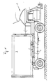
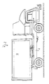
- the pour-in opening is located in the front area of the vehicle, partly above the driver's cab and partly between it and the container in the area behind and above the driver's cab, a lifting and tipping device receiving the refuse containers for emptying into the pour-in opening.
- the press shield guided in the bulk room is moved back and forth by hydraulic piston-cylinder units in such a way that it empties waste into the pouring opening through a filling opening provided with a closure device into the Insert container.
- the press plate can be moved into the container through the closable filling opening in the manner shown in FIG.
- the object of the invention is therefore to provide a safety device for a refuse collection vehicle of the type specified at the outset, which prevents damage to the refuse collection vehicle as a result of objects emptied into the bulk space and jamming between the press ram and parts of the bulk space or the container.
- this object is achieved in a refuse collection vehicle of the generic type in that a sensor is arranged in the upper region of the open extension side of the bulk room, which generates a signal in the event of jams or impacts of jammed or bulky objects, which stops the advance of the press plate or its drive reversed to return.
- the sensor provided according to the invention thus prevents bulky, protruding or inclined objects between the press plate and built-in parts of the dump or the pouring opening or the container can be jammed in such a way that damage occurs.
- the drive for the advance of the press plate is immediately switched to return, so that the driver or the operator knows, based on a corresponding display, that canting or clogging parts are in the bulk space that have to be removed.
- pivotable levers or claws are arranged by a drive, which loosen objects that are jammed and jammed in the pouring opening from the walls and press into the bulk space in this way that these can be grasped there by the press plate.
- Such pivotable levers or claws are expediently designed such that they still protrude from the filling opening of the container after the pressing plate has been moved back Parts can be pushed into it so that the container can be closed. Such parts protruding from the filler opening can occur in particular if they have become jammed between the slide-like press plate and the edges of the filler opening, so that they are taken along when the press plate is retracted and pulled out of the container again.
- the sensor expediently consists of at least one nose attached to a shaft.
- the shaft can be mounted in the walls of the bulk room above the open extension side. If the sensor is acted upon by canted or jamming objects, it exerts a torque on the shaft, with a switch or the like upon rotation of the shaft. is actuated, which triggers the signal.
- At least one claw can also be attached to the shaft, so that the shaft can be rotated by a special drive device in order to break a jam with the aid of the claw or to push jammed objects into the bulk space or the filling opening of the container.
- the sensor and / or the claw are expediently designed in the form of strips. In this way, they can monitor the entire width of the bulk space or intervene in it over the entire width.
- the shaft is provided with a lever in the manner of a crank, on the free end of which a hydraulic pressure medium-piston-cylinder unit acts.
- This pressure medium-piston-cylinder unit can be used both as a sensing element and as Act drive. If the piston-cylinder unit is not pressurized to rotate the shaft, the pressure in the cylinder is increased via the piston when a torque is exerted on the shaft via the sensor. This pressure increase can be detected by a pressure sensor or switch, which then triggers control and / or alarm signals.
- the piston-cylinder unit can be supplied with pressure medium in the usual way for rotating the shaft.
- the refuse collection vehicle 1 shown in FIGS. 1 and 2 corresponds to its basic structure according to the refuse collection vehicle described in the publication EP-0 163 859 A2, so that reference is made to this as a whole for a more detailed illustration of the refuse collection vehicle.
- a container 3, designed as an interchangeable container, is detachably fastened on the vehicle frame 2 and is provided with a closable fill opening on its side facing the driver's cab.
- the pouring space 5 into which the pouring opening 4 opens in a funnel-like manner.
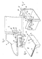
- the slide-like press ram 6 is guided to and fro.
- the press plate 6 has a front rectangular slide-like part 7 and a support plate 8 connected at right angles thereto.
- the press plate 6 is provided with lateral guide strips 9, which are guided in the guide grooves 10, which are formed in the side walls of the bulk space 5 by U-profiles embedded therein.
- the piston rods of articulated hydraulic cylinders 12, 13 are articulated on the back of its front slide part 7, the cylinders of which are articulated on a rear side wall of the bulkhead facing the driver's cabin.
- the bulk space and the design of the press plate and the hydraulic cylinders moving it correspond to the design described with reference to FIGS. 6 to 8 according to the publication EP 0 163 859 A1, but the piston rods are articulated directly on the front press plate and the toggle linkage is dispensed with .
- the side walls 15, 16 of the bulk space 5 are stiffened by a transverse traverse, not shown, or by the transverse wall of the pouring opening 4.
- a shaft 19 is mounted in the side walls 15, 16 of the bulk space or in carriers 17, 18 connected to it, on the shaft 17 of which protrudes beyond the carrier, a lever 20 is attached in a crank-like manner, at the free end of which the Piston rod of a hydraulic cylinder 22 is articulated, which is articulated by the articulated connection 23 to the side wall 15 of the bulk space 5 or another part fixed to the vehicle.
- the shaft 19 is connected to a bar 24 which is approximately nose-shaped in profile and at an obtuse angle to it with a bar 25 which forms a slide.
- the nose-shaped bar 24 lies just above the upper edge of the press plate 6 and is slightly inclined towards the filling opening 27 of the container 3.
- the bar 25 forming a pivotable slide lies approximately horizontally to the plane of displacement of the press plate 6.
- the shaft 19 is arranged just below the upper edge 28 of the fill opening 27 in the end region of the pouring space or in the boundary region between the pouring opening and the pouring space, so that the nose-shaped bar 27 forming a sensor acts on it is when bulky or transverse parts are clamped between this and the upper edge 30 of the press plate 6.
- slide-shaped bar 25 has the function of a sensor, since this is also pivoted when bulky or jammed parts lie between it and the press plate.
- the upper edge 30 of the press plate is chamfered in the manner shown in order to enable objects to slide better to avoid canting.
- the claw-like bar can not push protruding objects into the container by operating the hydraulic cylinder.
- the bar can only push objects protruding out of the container by twisting them over the piston-cylinder unit, so that they can be gripped by the reciprocating press plate and pushed into the container.
- Objects may jam or jam above the bulk space 5 in the pouring opening 4 if, for example, objects are jammed or jammed between the funnel-shaped, inclined wall 32 and the opposite wall of the pouring opening. If such a jamming or jamming occurs, the objects can be pressed down into the bulk space 5 by pivoting the claw-like bar 25 so that they can be gripped by the press plate 6.
- the shaft 19 is controlled such that the press plate 6 cannot move against the claw-like bar 25.
Landscapes
- Engineering & Computer Science (AREA)
- Mechanical Engineering (AREA)
- Refuse-Collection Vehicles (AREA)
- Refuse Collection And Transfer (AREA)
- Filters For Electric Vacuum Cleaners (AREA)
Priority Applications (1)
| Application Number | Priority Date | Filing Date | Title |
|---|---|---|---|
| AT91106131T ATE83737T1 (de) | 1990-04-26 | 1991-04-17 | Muellsammelfahrzeug. |
Applications Claiming Priority (2)
| Application Number | Priority Date | Filing Date | Title |
|---|---|---|---|
| DE4013433A DE4013433A1 (de) | 1990-04-26 | 1990-04-26 | Muellsammelfahrzeug |
| DE4013433 | 1990-04-26 |
Publications (2)
| Publication Number | Publication Date |
|---|---|
| EP0453940A1 true EP0453940A1 (fr) | 1991-10-30 |
| EP0453940B1 EP0453940B1 (fr) | 1992-12-23 |
Family
ID=6405201
Family Applications (1)
| Application Number | Title | Priority Date | Filing Date |
|---|---|---|---|
| EP91106131A Expired - Lifetime EP0453940B1 (fr) | 1990-04-26 | 1991-04-17 | Véhicule de ramassage d'ordures |
Country Status (5)
| Country | Link |
|---|---|
| EP (1) | EP0453940B1 (fr) |
| AT (1) | ATE83737T1 (fr) |
| CA (1) | CA2041350A1 (fr) |
| DE (2) | DE4013433A1 (fr) |
| ES (1) | ES2038058T3 (fr) |
Cited By (2)
| Publication number | Priority date | Publication date | Assignee | Title |
|---|---|---|---|---|
| WO1993015981A3 (fr) * | 1992-02-12 | 1993-12-23 | Edgar Georg | Vehicule pour collecter et transporter des dechets |
| CN112407697A (zh) * | 2020-11-05 | 2021-02-26 | 湖南林宇科技发展有限公司 | 一种车厢可拆卸式垃圾车 |
Families Citing this family (3)
| Publication number | Priority date | Publication date | Assignee | Title |
|---|---|---|---|---|
| US5344273A (en) * | 1992-08-10 | 1994-09-06 | Shu-Pak Refuse Equipment Inc. | Double-tier side loading refuse vehicle |
| DE10221827B4 (de) * | 2002-05-10 | 2005-04-14 | Zöller-Kipper GmbH | Verfahren und Vorrichtung zum Beschicken eines Behälters mit Feststoffen |
| CN110834849A (zh) * | 2019-11-20 | 2020-02-25 | 湖北一专汽车股份有限公司 | 一种勾臂垃圾车装载控制系统 |
Citations (3)
| Publication number | Priority date | Publication date | Assignee | Title |
|---|---|---|---|---|
| DE1145995B (de) * | 1959-04-28 | 1963-03-21 | City Tank Corp | Abfallsammelwagen mit in der Ladeoeffnung angeordneter Packerplatte |
| US3799051A (en) * | 1972-10-18 | 1974-03-26 | Carrier Corp | Refuse compacting device |
| EP0163859B1 (fr) * | 1984-05-29 | 1989-11-29 | Edelhoff M.S.T.S. Gmbh | Véhicule à ordures comportant une benne collectrice construite sous la forme d'un récipient interchangeable |
-
1990
- 1990-04-26 DE DE4013433A patent/DE4013433A1/de not_active Withdrawn
-
1991
- 1991-04-17 EP EP91106131A patent/EP0453940B1/fr not_active Expired - Lifetime
- 1991-04-17 ES ES199191106131T patent/ES2038058T3/es not_active Expired - Lifetime
- 1991-04-17 AT AT91106131T patent/ATE83737T1/de not_active IP Right Cessation
- 1991-04-17 DE DE9191106131T patent/DE59100019D1/de not_active Expired - Fee Related
- 1991-04-26 CA CA002041350A patent/CA2041350A1/fr not_active Abandoned
Patent Citations (3)
| Publication number | Priority date | Publication date | Assignee | Title |
|---|---|---|---|---|
| DE1145995B (de) * | 1959-04-28 | 1963-03-21 | City Tank Corp | Abfallsammelwagen mit in der Ladeoeffnung angeordneter Packerplatte |
| US3799051A (en) * | 1972-10-18 | 1974-03-26 | Carrier Corp | Refuse compacting device |
| EP0163859B1 (fr) * | 1984-05-29 | 1989-11-29 | Edelhoff M.S.T.S. Gmbh | Véhicule à ordures comportant une benne collectrice construite sous la forme d'un récipient interchangeable |
Cited By (2)
| Publication number | Priority date | Publication date | Assignee | Title |
|---|---|---|---|---|
| WO1993015981A3 (fr) * | 1992-02-12 | 1993-12-23 | Edgar Georg | Vehicule pour collecter et transporter des dechets |
| CN112407697A (zh) * | 2020-11-05 | 2021-02-26 | 湖南林宇科技发展有限公司 | 一种车厢可拆卸式垃圾车 |
Also Published As
| Publication number | Publication date |
|---|---|
| CA2041350A1 (fr) | 1991-10-27 |
| ES2038058T3 (es) | 1993-07-01 |
| DE59100019D1 (de) | 1993-02-04 |
| ATE83737T1 (de) | 1993-01-15 |
| DE4013433A1 (de) | 1991-10-31 |
| EP0453940B1 (fr) | 1992-12-23 |
Similar Documents
| Publication | Publication Date | Title |
|---|---|---|
| DE2126780C3 (de) | Mullfahrzeug mit hinter dem Sammelbehalter gelegenem Einfullraum und einem trogförmigen Vorverdichtungs raum | |
| EP0235784B1 (fr) | Dispositif de culbutage pour un véhicule à ordures | |
| DE1556516C3 (de) | Vorrichtung zum kontinuierlichen oder diskontinuierlichen Beladen des Ladebehälters eines Müllfahrzeuges | |
| DE1247937B (de) | Transportfahrzeug fuer Schuettgut wie Muell od. dgl. | |
| EP0336003A2 (fr) | Véhicule à ordures | |
| DE3543102C2 (fr) | ||
| EP2658707A1 (fr) | Dispositif de transport et/ou de pressage avec un dispositif d'alimentation monté en amont | |
| WO1995031388A1 (fr) | Vehicule de collecte des dechets | |
| EP0453940B1 (fr) | Véhicule de ramassage d'ordures | |
| EP2085330A1 (fr) | Véhicule pour déchets avec au moins un récipient collecteur et un dispositif de chargement | |
| CH564467A5 (en) | Equipment for filling and compressing garbage - has arrangement for alternately opening feeder and compressing garbage | |
| DE3210338C2 (fr) | ||
| DE69000736T2 (de) | Anordnung zum laden und entladen von mindestens zwei arten von abfallmaterialien. | |
| DE3447814A1 (de) | Entladevorrichtung bei einem muellsammelfahrzeug | |
| DE69400482T2 (de) | Vorrichtung und Verfahren zum getrennten Sammeln und Verdichten von Müll in einem Müllsammelfahrzeug | |
| DE3539206C1 (en) | Refuse collection vehicle | |
| DE2216056C3 (de) | Müllpresse | |
| EP2524881B1 (fr) | Véhicule pour déchets avec trémie de chargement et un dispositif de commande destiné au blocage d'une zone partielle | |
| DE4315506C2 (de) | Müllentsorgungsfahrzeug | |
| DE2218991C3 (de) | Preßbehälter für die Müllabfuhr | |
| DE2742401A1 (de) | Beladevorrichtung fuer schuettgutbehaelter, insbesondere muellwagensammelbehaelter | |
| DE1185533B (de) | Beladeeinrichtung fuer Muellwagen | |
| DE4243112A1 (de) | Müllsammelfahrzeug | |
| DE2709141A1 (de) | Beschickungseinrichtung fuer muellsammelfahrzeuge | |
| DE2247041A1 (de) | Muellbehaelter |
Legal Events
| Date | Code | Title | Description |
|---|---|---|---|
| PUAI | Public reference made under article 153(3) epc to a published international application that has entered the european phase |
Free format text: ORIGINAL CODE: 0009012 |
|
| AK | Designated contracting states |
Kind code of ref document: A1 Designated state(s): AT BE CH DE DK ES FR GB GR IT LI LU NL SE |
|
| 17P | Request for examination filed |
Effective date: 19910912 |
|
| 17Q | First examination report despatched |
Effective date: 19920429 |
|
| GRAA | (expected) grant |
Free format text: ORIGINAL CODE: 0009210 |
|
| AK | Designated contracting states |
Kind code of ref document: B1 Designated state(s): AT BE CH DE DK ES FR GB GR IT LI LU NL SE |
|
| PG25 | Lapsed in a contracting state [announced via postgrant information from national office to epo] |
Ref country code: SE Effective date: 19921223 Ref country code: GR Free format text: LAPSE BECAUSE OF FAILURE TO SUBMIT A TRANSLATION OF THE DESCRIPTION OR TO PAY THE FEE WITHIN THE PRESCRIBED TIME-LIMIT Effective date: 19921223 Ref country code: DK Effective date: 19921223 |
|
| REF | Corresponds to: |
Ref document number: 83737 Country of ref document: AT Date of ref document: 19930115 Kind code of ref document: T |
|
| ITF | It: translation for a ep patent filed | ||
| REF | Corresponds to: |
Ref document number: 59100019 Country of ref document: DE Date of ref document: 19930204 |
|
| GBT | Gb: translation of ep patent filed (gb section 77(6)(a)/1977) |
Effective date: 19930216 |
|
| ET | Fr: translation filed | ||
| PG25 | Lapsed in a contracting state [announced via postgrant information from national office to epo] |
Ref country code: AT Effective date: 19930417 |
|
| PG25 | Lapsed in a contracting state [announced via postgrant information from national office to epo] |
Ref country code: LU Free format text: LAPSE BECAUSE OF NON-PAYMENT OF DUE FEES Effective date: 19930430 Ref country code: LI Effective date: 19930430 Ref country code: CH Effective date: 19930430 |
|
| REG | Reference to a national code |
Ref country code: ES Ref legal event code: FG2A Ref document number: 2038058 Country of ref document: ES Kind code of ref document: T3 |
|
| PLBE | No opposition filed within time limit |
Free format text: ORIGINAL CODE: 0009261 |
|
| STAA | Information on the status of an ep patent application or granted ep patent |
Free format text: STATUS: NO OPPOSITION FILED WITHIN TIME LIMIT |
|
| 26N | No opposition filed | ||
| REG | Reference to a national code |
Ref country code: CH Ref legal event code: PL |
|
| PGFP | Annual fee paid to national office [announced via postgrant information from national office to epo] |
Ref country code: FR Payment date: 20000131 Year of fee payment: 10 |
|
| PGFP | Annual fee paid to national office [announced via postgrant information from national office to epo] |
Ref country code: DE Payment date: 20000201 Year of fee payment: 10 |
|
| PGFP | Annual fee paid to national office [announced via postgrant information from national office to epo] |
Ref country code: BE Payment date: 20000208 Year of fee payment: 10 |
|
| PGFP | Annual fee paid to national office [announced via postgrant information from national office to epo] |
Ref country code: ES Payment date: 20000302 Year of fee payment: 10 |
|
| PGFP | Annual fee paid to national office [announced via postgrant information from national office to epo] |
Ref country code: GB Payment date: 20000412 Year of fee payment: 10 |
|
| PGFP | Annual fee paid to national office [announced via postgrant information from national office to epo] |
Ref country code: NL Payment date: 20000428 Year of fee payment: 10 |
|
| PG25 | Lapsed in a contracting state [announced via postgrant information from national office to epo] |
Ref country code: GB Free format text: LAPSE BECAUSE OF NON-PAYMENT OF DUE FEES Effective date: 20010417 |
|
| PG25 | Lapsed in a contracting state [announced via postgrant information from national office to epo] |
Ref country code: ES Free format text: LAPSE BECAUSE OF NON-PAYMENT OF DUE FEES Effective date: 20010418 |
|
| PG25 | Lapsed in a contracting state [announced via postgrant information from national office to epo] |
Ref country code: FR Free format text: THE PATENT HAS BEEN ANNULLED BY A DECISION OF A NATIONAL AUTHORITY Effective date: 20010430 Ref country code: BE Free format text: LAPSE BECAUSE OF NON-PAYMENT OF DUE FEES Effective date: 20010430 |
|
| BERE | Be: lapsed |
Owner name: EDELHOFF POLYTECHNIK G.M.B.H. & CO. Effective date: 20010430 |
|
| PG25 | Lapsed in a contracting state [announced via postgrant information from national office to epo] |
Ref country code: NL Free format text: LAPSE BECAUSE OF NON-PAYMENT OF DUE FEES Effective date: 20011101 |
|
| GBPC | Gb: european patent ceased through non-payment of renewal fee |
Effective date: 20010417 |
|
| NLV4 | Nl: lapsed or anulled due to non-payment of the annual fee |
Effective date: 20011101 |
|
| PG25 | Lapsed in a contracting state [announced via postgrant information from national office to epo] |
Ref country code: DE Free format text: LAPSE BECAUSE OF NON-PAYMENT OF DUE FEES Effective date: 20020201 |
|
| REG | Reference to a national code |
Ref country code: FR Ref legal event code: ST |
|
| REG | Reference to a national code |
Ref country code: ES Ref legal event code: FD2A Effective date: 20030203 |
|
| PG25 | Lapsed in a contracting state [announced via postgrant information from national office to epo] |
Ref country code: IT Free format text: LAPSE BECAUSE OF NON-PAYMENT OF DUE FEES Effective date: 20050417 |