EP0454013A2 - Circuit de mesure pour détecter un courant - Google Patents
Circuit de mesure pour détecter un courant Download PDFInfo
- Publication number
- EP0454013A2 EP0454013A2 EP91106413A EP91106413A EP0454013A2 EP 0454013 A2 EP0454013 A2 EP 0454013A2 EP 91106413 A EP91106413 A EP 91106413A EP 91106413 A EP91106413 A EP 91106413A EP 0454013 A2 EP0454013 A2 EP 0454013A2
- Authority
- EP
- European Patent Office
- Prior art keywords
- current
- shunt
- measuring
- measuring circuit
- input
- Prior art date
- Legal status (The legal status is an assumption and is not a legal conclusion. Google has not performed a legal analysis and makes no representation as to the accuracy of the status listed.)
- Granted
Links
Images
Classifications
-
- G—PHYSICS
- G01—MEASURING; TESTING
- G01R—MEASURING ELECTRIC VARIABLES; MEASURING MAGNETIC VARIABLES
- G01R19/00—Arrangements for measuring currents or voltages or for indicating presence or sign thereof
- G01R19/165—Indicating that current or voltage is either above or below a predetermined value or within or outside a predetermined range of values
- G01R19/16566—Circuits and arrangements for comparing voltage or current with one or several thresholds and for indicating the result not covered by subgroups G01R19/16504, G01R19/16528, G01R19/16533
- G01R19/16571—Circuits and arrangements for comparing voltage or current with one or several thresholds and for indicating the result not covered by subgroups G01R19/16504, G01R19/16528, G01R19/16533 comparing AC or DC current with one threshold, e.g. load current, over-current, surge current or fault current
Definitions
- the invention relates to a measuring circuit of the type mentioned in the preamble of claim 1.
- VBG 4 Electronic systems and equipment
- all devices and equipment of protection class II have to be checked at certain intervals or after a repair a repair test.
- the leakage current flowing between touchable conductive parts of the object to be checked and earth or a protective conductor must be measured.
- the one between the touchable conductive parts and e.g. leakage current flowing to the protective contact of a socket must not exceed a specified value (e.g. 0.25 mA).
- the internal resistance of the measuring circuit used to measure the current should be a maximum of 2 kOhm.
- the object of the invention is therefore to provide a measuring circuit according to the preamble of claim 1, which leads to a significantly excessive display value at an impermissibly high current detected by the measuring circuit without the measuring device being endangered.
- a fuse is a current limiting element that interrupts the circuit in the event of a fault and thus reduces the current to zero.
- a current branch bridging the current limiting element, according to the invention it is still possible to supply a current to the input of a measuring device even when the actual measuring circuit is interrupted. To ensure that normally no current falsifying the measurement result flows through the current branch, this may only be switched on in the event of a fault. This is done with the help of a limit value element, which is only activated when its limit voltage is exceeded, which in turn is limited to the event of a fault. The signal now generated ensures that the display of the measuring device overflows, as a result of which an excessively high current is clearly signaled.
- the current consumed by the measuring circuit must be passed through a shunt so that a signal that can be processed by the measuring device is produced.
- a first shunt is thus provided in the measuring circuit and a second shunt is provided in the secondary current branch.
- a particularly expedient embodiment of the invention now provides that the first shunt forms a series connection at the input of the measuring device with the second shunt.
- the second shunt is de-energized and is therefore in series with the measurement of the voltage drop generated by the measuring current at the first shunt in series with the much higher impedance input resistance of the measuring device, so that it remains without influence on the measurement.
- the current consumed by the secondary current branch at the series connection of the first and the second shunt generates a signal which is fed to the input of the measuring device and which is so large that the overflow is reached.
- a particularly simple solution is to use two Zener diodes connected in opposite poles, which form the secondary current branch with a series resistor and the second shunt.
- a particularly advantageous development of the subject matter of the invention uses a PTC resistor as the current limiting element. In the event of an error, this limits the Input current of the measuring circuit with appropriate dimensioning to values below 1 mA. The voltage drop generated in this way would simulate a permissible measuring current, so that the display overflow control according to the invention achieved by the secondary current branch becomes more important.
- a major advantage of the PTC resistor compared to a fuse is the fact that it retains its protective effect and resumes its initial resistance after the fault has been eliminated. This eliminates the need to replace a damaged component (fuse) and keep it in stock, which would otherwise be necessary to ensure the operational readiness of the measuring device.
- the second shunt which is preferably designed to be 10 to 20 times larger than the first shunt, enables the measuring device to be controlled into the display overflow area even with a relatively small current in the secondary current branch.
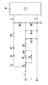
- the measuring circuit consists of the series connection of a PTC resistor R1, a supplementary resistor R2, and the first shunt R5, which is bridged by two diodes V3, V4 connected in anti-parallel.
- the PTC resistor R1 can also be replaced by a fuse or another type of fuse that breaks the circuit.
- the secondary current branch is formed from the series connection of two Zener diodes V1, V2 connected in opposite polarity, a series resistor R3 and the second shunt R4. It bridges the PTC resistor R1 with the subsequent supplementary resistor R2.
- the first shunt R5 is dimensioned such that the voltage drop generated at it is lower than the threshold voltage of the two diodes V3, V4.
- the PTC resistor tilts into its high-resistance Condition and ensures that only a reduced measuring circuit current I1 is absorbed by the leakage current I consumed.
- the measuring circuit current reduced to a value below 1 mA is within the normal measuring range and would therefore simulate a permissible leakage current. This is prevented by the secondary current branch with the help of the two Zener diodes V1, V2, which respond due to the increased voltage drop across the PTC resistor R1 and now conduct a branch circuit current I2 via the series resistor R3 and the two shunts R4, R5.
- the series resistor R3 is high-resistance and dimensioned for the maximum overload.
- the total resistance from the series connection of the two shunts R4, R5 is determined in such a way that the voltage drop generated at it clearly exceeds the upper limit of the measuring range and thereby signals an error. It is expedient to dimension the resistance value of the second shunt R4 by a factor of 10 to 20 larger than that of the first shunt R5.
Landscapes
- Engineering & Computer Science (AREA)
- Power Engineering (AREA)
- Physics & Mathematics (AREA)
- General Physics & Mathematics (AREA)
- Measurement Of Current Or Voltage (AREA)
- Emergency Protection Circuit Devices (AREA)
- Interface Circuits In Exchanges (AREA)
- Testing Of Short-Circuits, Discontinuities, Leakage, Or Incorrect Line Connections (AREA)
Applications Claiming Priority (2)
| Application Number | Priority Date | Filing Date | Title |
|---|---|---|---|
| DE4013488 | 1990-04-27 | ||
| DE4013488A DE4013488A1 (de) | 1990-04-27 | 1990-04-27 | Messschaltung zur erfassung eines stromes |
Publications (3)
| Publication Number | Publication Date |
|---|---|
| EP0454013A2 true EP0454013A2 (fr) | 1991-10-30 |
| EP0454013A3 EP0454013A3 (en) | 1992-06-03 |
| EP0454013B1 EP0454013B1 (fr) | 1995-02-15 |
Family
ID=6405234
Family Applications (1)
| Application Number | Title | Priority Date | Filing Date |
|---|---|---|---|
| EP91106413A Expired - Lifetime EP0454013B1 (fr) | 1990-04-27 | 1991-04-22 | Circuit de mesure pour détecter un courant |
Country Status (4)
| Country | Link |
|---|---|
| EP (1) | EP0454013B1 (fr) |
| AT (1) | ATE118620T1 (fr) |
| CZ (1) | CZ280023B6 (fr) |
| DE (2) | DE4013488A1 (fr) |
Cited By (1)
| Publication number | Priority date | Publication date | Assignee | Title |
|---|---|---|---|---|
| CN113791271A (zh) * | 2021-09-30 | 2021-12-14 | 深圳市银星智能科技股份有限公司 | 电流检测电路和设备 |
Family Cites Families (2)
| Publication number | Priority date | Publication date | Assignee | Title |
|---|---|---|---|---|
| NL8001452A (nl) * | 1980-03-12 | 1981-10-01 | Philips Nv | Beveiligde stroommeetschakeling. |
| DE3834183A1 (de) * | 1988-10-07 | 1990-04-12 | Asea Brown Boveri | Elektronisches mehrbereichsmessgeraet |
-
1990
- 1990-04-27 DE DE4013488A patent/DE4013488A1/de not_active Withdrawn
-
1991
- 1991-04-22 EP EP91106413A patent/EP0454013B1/fr not_active Expired - Lifetime
- 1991-04-22 DE DE59104568T patent/DE59104568D1/de not_active Expired - Lifetime
- 1991-04-22 AT AT91106413T patent/ATE118620T1/de not_active IP Right Cessation
- 1991-04-25 CZ CS911183A patent/CZ280023B6/cs not_active IP Right Cessation
Cited By (1)
| Publication number | Priority date | Publication date | Assignee | Title |
|---|---|---|---|---|
| CN113791271A (zh) * | 2021-09-30 | 2021-12-14 | 深圳市银星智能科技股份有限公司 | 电流检测电路和设备 |
Also Published As
| Publication number | Publication date |
|---|---|
| EP0454013B1 (fr) | 1995-02-15 |
| DE4013488A1 (de) | 1991-10-31 |
| EP0454013A3 (en) | 1992-06-03 |
| CZ280023B6 (cs) | 1995-09-13 |
| DE59104568D1 (de) | 1995-03-23 |
| ATE118620T1 (de) | 1995-03-15 |
| CS9101183A2 (en) | 1991-11-12 |
Similar Documents
| Publication | Publication Date | Title |
|---|---|---|
| DE3819529C2 (de) | Elektrische Thermomagnet- und Differentialschutzeinrichtung | |
| DE19842470A1 (de) | Fehlerstrom-Schutzeinrichtung mit Überlastschutz | |
| DE4109586C2 (de) | Schaltungsanordnung zur Isolationsüberwachung ungeerdeter Niederspannungsnetze | |
| EP0909956B1 (fr) | Procédé et détermination de la résistance d'un réseau de distribution électrique | |
| DE1140634B (de) | Sicherheitsschalter zum Schutze gegen elektrische Kriechstroeme | |
| DE3216497A1 (de) | Vorrichtung zur inbetriebnahme der fernspeisung von elektrischen verbrauchern und schaltungsanordnung zur durchfuehrung des verfahrens | |
| EP0454013B1 (fr) | Circuit de mesure pour détecter un courant | |
| DE112016003893T5 (de) | Automatischer Fehlerstromschutzprüfer | |
| DE4013490C2 (de) | Prüfgerät mit einer Gleichstromquelle | |
| DE4027804A1 (de) | Messverfahren zum messen unterschiedlicher messgroessen und multimeter zur durchfuehrung des verfahrens | |
| EP0864873A1 (fr) | Procédé pour déterminer la résistance de terre et réseau électrique adapté | |
| WO2003073577A1 (fr) | Dispositif de controle destine a un disjoncteur comportant un declencheur electronique | |
| EP0349880A1 (fr) | Dispositif de protection contre les courants de défaut | |
| DE69325381T2 (de) | Sensor zur fehlerstromerfassung | |
| DE2546997C2 (de) | Schaltungsanordnung zur Isolationsüberwachung eines nicht geerdeten Gleichstromnetzes | |
| DE19943801A1 (de) | Fehlerstrom-Schutzeinrichtung | |
| DE60306615T2 (de) | Verfahren zur Überwachung eines elektrischen Kontakts | |
| DE102018219692A1 (de) | Schutzschaltgerät für einen Niederspannungsstromkreis zur Erkennung von seriellen Fehlerlichtbögen | |
| DD282299A5 (de) | Schaltung zum ueberwachen des betriebsstromes in stromkreisen von gleichstrom-elektroenergieverbrauchern | |
| WO1998026299A1 (fr) | Dispositif de detection d'etat de n condensateurs de puissance appartenant a un groupe de condensateurs haute tension | |
| DE2948269A1 (de) | Schaltungsanordnung zur fernspeisung von zwischenstellen einer einrichtung der nachrichtenuebertragungstechnik mit ueberwachung der ausgangsspannung | |
| DD282300A5 (de) | Schaltung zum ueberwachen des betriebsstromes in stromkreisen von einphasenwechselstrom-elektroenergieverbrauchern | |
| DE2416784A1 (de) | Leitungswaechter fuer ungeerdete elektrische netze | |
| DE723933C (de) | Verfahren zur Ermittlung der fuer eine Stromentnahmestelle in Hinsicht auf den Schutz gegen Beruehrungsspannung durch Erdung oder Nullung zulaessigen Sicherungsgroesse | |
| DE4318502C1 (de) | Verfahren und Schaltung zur Überwachung der Ströme von Leistungskondensatoren zur Blindleistungskompensation |
Legal Events
| Date | Code | Title | Description |
|---|---|---|---|
| PUAI | Public reference made under article 153(3) epc to a published international application that has entered the european phase |
Free format text: ORIGINAL CODE: 0009012 |
|
| AK | Designated contracting states |
Kind code of ref document: A2 Designated state(s): AT CH DE FR GB LI |
|
| PUAL | Search report despatched |
Free format text: ORIGINAL CODE: 0009013 |
|
| AK | Designated contracting states |
Kind code of ref document: A3 Designated state(s): AT CH DE FR GB LI |
|
| 17P | Request for examination filed |
Effective date: 19921126 |
|
| RAP1 | Party data changed (applicant data changed or rights of an application transferred) |
Owner name: METRAWATT GMBH |
|
| RAP1 | Party data changed (applicant data changed or rights of an application transferred) |
Owner name: GOSSEN- METRAWATT GMBH |
|
| 17Q | First examination report despatched |
Effective date: 19940429 |
|
| GRAA | (expected) grant |
Free format text: ORIGINAL CODE: 0009210 |
|
| AK | Designated contracting states |
Kind code of ref document: B1 Designated state(s): AT CH DE FR GB LI |
|
| PG25 | Lapsed in a contracting state [announced via postgrant information from national office to epo] |
Ref country code: FR Effective date: 19950215 Ref country code: GB Effective date: 19950215 |
|
| REF | Corresponds to: |
Ref document number: 118620 Country of ref document: AT Date of ref document: 19950315 Kind code of ref document: T |
|
| REF | Corresponds to: |
Ref document number: 59104568 Country of ref document: DE Date of ref document: 19950323 |
|
| PG25 | Lapsed in a contracting state [announced via postgrant information from national office to epo] |
Ref country code: LI Effective date: 19950430 Ref country code: CH Effective date: 19950430 |
|
| EN | Fr: translation not filed | ||
| GBV | Gb: ep patent (uk) treated as always having been void in accordance with gb section 77(7)/1977 [no translation filed] |
Effective date: 19950215 |
|
| REG | Reference to a national code |
Ref country code: CH Ref legal event code: PL |
|
| PLBE | No opposition filed within time limit |
Free format text: ORIGINAL CODE: 0009261 |
|
| STAA | Information on the status of an ep patent application or granted ep patent |
Free format text: STATUS: NO OPPOSITION FILED WITHIN TIME LIMIT |
|
| 26N | No opposition filed | ||
| PGFP | Annual fee paid to national office [announced via postgrant information from national office to epo] |
Ref country code: AT Payment date: 19990422 Year of fee payment: 9 |
|
| PG25 | Lapsed in a contracting state [announced via postgrant information from national office to epo] |
Ref country code: AT Free format text: LAPSE BECAUSE OF NON-PAYMENT OF DUE FEES Effective date: 20000422 |
|
| PGFP | Annual fee paid to national office [announced via postgrant information from national office to epo] |
Ref country code: DE Payment date: 20100429 Year of fee payment: 20 |
|
| REG | Reference to a national code |
Ref country code: DE Ref legal event code: R071 Ref document number: 59104568 Country of ref document: DE |
|
| PG25 | Lapsed in a contracting state [announced via postgrant information from national office to epo] |
Ref country code: DE Free format text: LAPSE BECAUSE OF EXPIRATION OF PROTECTION Effective date: 20110422 |