EP0454093A2 - Spindle apparatus for supporting and rotating a workpiece - Google Patents
Spindle apparatus for supporting and rotating a workpiece Download PDFInfo
- Publication number
- EP0454093A2 EP0454093A2 EP19910106609 EP91106609A EP0454093A2 EP 0454093 A2 EP0454093 A2 EP 0454093A2 EP 19910106609 EP19910106609 EP 19910106609 EP 91106609 A EP91106609 A EP 91106609A EP 0454093 A2 EP0454093 A2 EP 0454093A2
- Authority
- EP
- European Patent Office
- Prior art keywords
- workpiece
- spindle
- ram
- rotation
- moved
- Prior art date
- Legal status (The legal status is an assumption and is not a legal conclusion. Google has not performed a legal analysis and makes no representation as to the accuracy of the status listed.)
- Ceased
Links
Images



Classifications
-
- B—PERFORMING OPERATIONS; TRANSPORTING
- B24—GRINDING; POLISHING
- B24B—MACHINES, DEVICES, OR PROCESSES FOR GRINDING OR POLISHING; DRESSING OR CONDITIONING OF ABRADING SURFACES; FEEDING OF GRINDING, POLISHING, OR LAPPING AGENTS
- B24B41/00—Component parts such as frames, beds, carriages, headstocks
- B24B41/06—Work supports, e.g. adjustable steadies
-
- B—PERFORMING OPERATIONS; TRANSPORTING
- B24—GRINDING; POLISHING
- B24B—MACHINES, DEVICES, OR PROCESSES FOR GRINDING OR POLISHING; DRESSING OR CONDITIONING OF ABRADING SURFACES; FEEDING OF GRINDING, POLISHING, OR LAPPING AGENTS
- B24B19/00—Single-purpose machines or devices for particular grinding operations not covered by any other main group
- B24B19/08—Single-purpose machines or devices for particular grinding operations not covered by any other main group for grinding non-circular cross-sections, e.g. shafts of elliptical or polygonal cross-section
- B24B19/12—Single-purpose machines or devices for particular grinding operations not covered by any other main group for grinding non-circular cross-sections, e.g. shafts of elliptical or polygonal cross-section for grinding cams or camshafts
-
- B—PERFORMING OPERATIONS; TRANSPORTING
- B24—GRINDING; POLISHING
- B24B—MACHINES, DEVICES, OR PROCESSES FOR GRINDING OR POLISHING; DRESSING OR CONDITIONING OF ABRADING SURFACES; FEEDING OF GRINDING, POLISHING, OR LAPPING AGENTS
- B24B41/00—Component parts such as frames, beds, carriages, headstocks
- B24B41/06—Work supports, e.g. adjustable steadies
- B24B41/061—Work supports, e.g. adjustable steadies axially supporting turning workpieces, e.g. magnetically, pneumatically
Definitions
- the present invention relates to a spindle apparatus for supporting and rotating a workpiece, particularly, wherein a spindle center can be displaced in the axial direction of a spindle.
- a cylindrical grinder designed to grind a cylindrical workpiece or a cam grinder is generally constructed as shown in Fig. 1.
- a wheel head 102 and a table 103 are arranged on a bed 101 and are slidable along guides in vertical and lateral directions in the drawing, respectively.
- a wheel shaft 105 is supported on the wheel head 102 and is driven for rotation by a motor 106 through a belt-and-pulley mechanism 107.
- a pair of grinding wheels 104a and 104b are mounted to the wheel shaft 105.
- a spindle head 110 is mounted on one end of the table 103.
- a workpiece spindle 109 is supported by the spindle head 110 and driven in rotation from a motor 108.
- the workpiece spindle 109 includes a chuck and a center 129.
- Mounted on the other end of the table 103 is a tailstock 113 including a tailstock spindle 112.
- the tailstock spindle 112 includes a center 111 in a face-to-face relation to the workpiece spindle 109.
- a pair of workpiece stand-by stations 114a and 114b are located on the table 103 adjacent to front ends of the workpiece spindle 109 and the tailstock spindle 112.
- An instrument 115 is provided on the bed 101 to sense the axial or longitudinal position of a workpiece.
- a workpiece shifter 150 is located on the table 103 between the workpiece spindle 109 and the tailstock spindle 112.
- the tailstock spindle 112 or the center 111 is in its retreated position before abrasive action is initiated.
- a workpiece W is loaded temporarily on the workpiece stand-by stations 115a and 115b by a loader or similar means.
- the workpiece W is thereafter moved toward the workpiece spindle 109 by the workpiece shifter 150 until one end of the workpiece W is brought into engagement with the center 129 of the workpiece spindle 109.
- the tailstock spindle 112 is then advanced so that the other end of the workpiece W is brought into engagement with the center 111.
- the end of the workpiece adjacent to the workpiece spindle is gripped by the chuck of the workpiece spindle 109.
- the wheel head 102 is advanced while the workpiece W is being rotated by the motor 108.
- the workpiece W is then abraded by the grinding wheels 104a and 104b which are rotated by the motor 106.
- the wheel head 102 is moved back or retreated, and the motor 108 is stopped.
- the workpiece W is then released from the chuck, and the tailstock spindle 112 is moved to its retreated position.
- the workpiece W is thereafter moved to the workpiece stand-by stations 114a and 114b by the workpiece shifter 150 and moved away from the system by the loader.
- the workpiece W is displaced from the workpiece stand-by stations 114a and 114b toward the workpiece spindle 109 by the workpiece shifter 150. This results in an increase in the distance between one end of the workpiece W and the tailstock spindle 112.
- the tailstock spindle 112 must project more toward the workpiece spindle 109 or must be moved more toward the workpiece spindle 109 to support the other end of the workpiece W in proportion to the displacement of the workpiece W by the workpiece shifter 150. This impairs the rigidity of the tailstock spindle 112.
- a further problem of the prior art is that it takes quite a time to support the workpiece since the workpiece shifter 150 must be used to load the workpiece, and the tailstock spindle 112 must be moved by an increased distance.
- Another object of the present invention is to provide a spindle apparatus which allows a tailstock spindle to support a workpiece with a lesser amount of movement so as to increase the rigidity of the tailstock spindle and to reduce the time required to support the workpiece.
- the present invention provides a spindle apparatus which comprises a workpiece spindle rotatably supported on a spindle head and driven for rotation by a motor, a ram slidably supported in a bore of the workpiece spindle and including a workpiece support portion at its front end, a unit for moving the ram to a predetermined advanced position to support the workpiece, a drive member rotatably supported on the front end of the ram and engageable with the workpiece in the direction of rotation when the ram has been moved to its advanced position, and a mechanism for transmitting rotation of the workpiece spindle to the drive member.
- the spindle apparatus eliminates the need for a workpiece shifter and its maintenance. It also provides an increased space on the grinder. This not only facilitates cleaning of the table, but also permits provision of a rest device. Additionally, the spindle apparatus can handle a workpiece of a greater weight since a workpiece shifter needs not be used to shift a workpiece.
- the tailstock spindle is moved a shorter distance than the prior art when the workpiece is to be supported. This improves the rigidity of the tailstock spindle and reduces the size of the tailstock and tailstock spindle. Further, the tailstock spindle is reciprocated a lesser amount of time than the prior art, and no time is required to operate the workpiece shifter. This results in a decrease in the time required to operate the system and in an increase in the operating efficiency.
- Fig. 2 shows a grinder incorporating a spindle apparatus of the present invention.
- a wheel head 2 and a table 3 are arranged on a bed 1 and slidable along guides in vertical and lateral directions in the drawing, respectively.
- a wheel shaft 5 is supported on the wheel head 2 and is driven for rotation by a motor 6 through a belt-and-pulley mechanism 7.
- a pair of grinding wheels 4a and 4b are mounted to the wheel shaft 5.
- a spindle head 10 is mounted on one end of the table 3.
- a workpiece spindle 9 is supported by the spindle head 10 and driven in rotation from a motor 8.
- Mounted on the other end of the table 3 is a tailstock 13 including a tailstock spindle 12.
- the tailstock spindle 12 includes a center 11 in a face-to-face relation to the workpiece spindle 9.
- a pair of workpiece stand-by stations 14a and 14b are located on the table 3 adjacent to front ends of the workpiece spindle 9 and the tailstock spindle 12.
- An instrument 15 is provided on the bed 1 to sense the axial or longitudinal position of a workpiece.
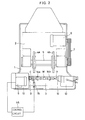
- the structure of the spindle head 10 is shown in detail in Fig. 3.
- the spindle head 10 includes a body 10a within which the workpiece 9 and a gear shaft 20 extend in parallel to one another and are rotatably supported by roller bearings 21, 21 and 22, 22, respectively.
- a spindle plate 24 is attached to the front end of the workpiece spindle 9 and includes an eccentric pin 23 extending axially of the spindle.
- a gear 25 is integrally formed on the rear end of the workpiece spindle 9 and meshed with a gear 26 which is, in turn, formed on the front end of the gear shaft 20.
- the rear end of the gear shaft 20 is coupled to the output shaft of the motor 8 through a joint 27.
- the workpiece spindle 9 includes an axially extending central bore.
- a ram support 10a is integral with the body 10a and has a front end extending into the central bore of the workpiece spindle 9 with a predetermined clearance left therebetween.
- a ram 28 extends into the ram support 10b and is slidable in a direction parallel to the axis of the workpiece spindle 9.
- a rod 37 is mounted within the body 10a and slidable in a direction parallel to the axis of the ram 28. The rear ends of the rod 37 and the ram 28 are interconnected together by a connecting plate 36. This allows the ram 28 to axially move, but restricts the ram 28 from rotating.
- a center 29 is fit in the front end of the ram 28.
- a rotary sleeve 32 is also rotatably mounted on the front end of the ram 28 through roller bearings 33 and 33.
- the rotary sleeve 32 includes a front flange 30 and a rear flange 31.
- the rear flange 31 has a groove 35 to receive a drive pin 23 which in turn, extends from the spindle plate 24.
- the front flange 30 has an opening 34 so as to prevent interference of the drive pin 23 with the rear flange 31 when the ram 28 is moved to its retreated position.
- a drive plate 52 is secured to the front of the front flange 30 and includes a central opening through which the front end of the center 29 extends.
- a screw shaft 39 is located within the spindle head 10 behind the ram 28.
- the screw shaft 39 is concentric with the ram 28 and is rotatably supported by a roller bearing 38.
- the screw shaft 39 includes at its front end a screw portion 39a for threaded engagement with a nut 40 which is, in turn, secured to the rear end of the ram 28.
- the screw shaft 39 has at its rear end a shaft portion 39b to which a gear 41 is mounted.
- a servo motor 42 is mounted to the spindle head 10 and has an output shaft to which a gear 43 is mounted for threaded engagement with the gear 41.
- a driving unit C is attached to the drive plate 52 and may be in the form of a hydraulically operated automatic dog clutch or in the form of a drive dog clutch such as shown in the drawing figures.
- the servo motor 42 is connected to a control circuit 44 and is controlled in response to a signal produced by axial position sensors 15a and 15b.
- the driving unit C is pivotably mounted to the front of the drive plate 52 and generally includes a floating member 54 and a pair of pawls 53 and 53.
- the floating member 54 includes a ring 56 having a central opening 55, and a pair of diametrically opposite arms 57 and 58 extending outwardly from the ring 56.
- the pawls 53 and 53 extend from the ring 56 in a diametrically opposite relation and are 90 ° out of phase with respect to the arms 57 and 58.
- Each pawl 53 has a front end extending into the central opening 55.
- the drive plate 52 has a bracket 59 on its front.
- the bracket 59 has a pivot pin about which the arm 57 of the floating member 54 is pivotable.
- the other arm 58 has an opening through which a bolt 62 extends.
- the bolt 62 is secured to the front of the drive plate 52 and has a head engaged with the front surface of the arm 58.
- Compression springs 58 and 58 are disposed between the front of the drive plate 52 and the arm 58 to bias the arm 58 so that the arm 58 may float relative to the drive plate 52.
- Guide elements 64 and 64 are attached to the drive plate 52 at opposite sides of the arm 58 so as to restrict displacement of the arm 58 in a circumferential direction.
- the tailstock spindle and the ram 28 are in their retreated position before abrasive action is initiated.
- the workpiece W is placed temporarily on the workpiece stand-by stations 14a and 14b by a loader or similar means. Thereafter, the workpiece spindle 9 is rotated at a low speed by the motor 8. Also, the servo motor 42 is driven to rotate the screw portion 39a of the screw shaft 39 through the gears 43 and 41. This causes the ram 28 with the nut 40 to slide forward within the workpiece spindle 9. With a slight delay, the tailstock spindle 12 is advanced. The workpiece W on the workpiece stand-by stations 14a and 14b is then supported by the centers 11 and 29.
- the floating member 54 may be moved toward the drive plate 52 against the action of the springs 63 and 63 in the event that the pawls 53 and 53 of the floating member 54 interferes with a portion of the workpiece W which is not bevelled.
- the pawls 53 and 53 are brought into engagement with a rotation transmission surface or bevel surface Wa which is formed on one end of the workpiece W.
- the axial position sensors 15a and 15a are moved forward to sense the axial position of the workpiece W.
- a signal indicative of the sensing is sent to the control circuit 44 so as to drive the servo motor 42 until the workpiece W is moved to a predetermined axial position.
- the ram 28 or the center 29 is advanced against the biasing force of the center 11 so as to hold the workpiece W in such a predetermined axial position.
- the workpiece W can thus be held in position without moving the table 3.
- the motor 8 is rotated at a higher speed to increase the speed of rotation of the workpiece W up to a predetermined level.
- the grinding wheels 4a and 4b are rotated by the motor 6 to initiate abrasive action.
- the driving unit which is engaged with the workpiece W is rotated in the following manner. Rotation of the motor 8 is transmitted to the driving unit C through the joint 27, the gear shaft 20, the gears 26 and 25, the workpiece spindle 9, the spindle plate 24, the drive pin 23, the rotary sleeve 32 and the drive plate 52. At this time, the drive pin 23 is always engaged with the groove 35 of the rear flange 31 of the rotary sleeve 32 regardless of whether the ram 28 is moved forwards or rearwards. The rotation can always be transmitted to the workpiece W.
- the wheel head 2 is retreated, and the motor 8 is stopped.
- the tailstock spindle 12 is moved to its retreated position.
- the servo motor is then rotated in a reverse direction so as to slide the ram 28 back to its retreated position through the gears 43 and 41, the screw portion 42a, and the nut 42.
- the workpiece W is released from the centers 11 and 12, placed on the workpiece stand-by stations 14a and 14b and then, moved away from the grinder by the loader.
Landscapes
- Engineering & Computer Science (AREA)
- Mechanical Engineering (AREA)
- Constituent Portions Of Griding Lathes, Driving, Sensing And Control (AREA)
- Turning (AREA)
Abstract
Description
- The present invention relates to a spindle apparatus for supporting and rotating a workpiece, particularly, wherein a spindle center can be displaced in the axial direction of a spindle.
- A cylindrical grinder designed to grind a cylindrical workpiece or a cam grinder is generally constructed as shown in Fig. 1.
- Specifically, a
wheel head 102 and a table 103 are arranged on abed 101 and are slidable along guides in vertical and lateral directions in the drawing, respectively. Awheel shaft 105 is supported on thewheel head 102 and is driven for rotation by amotor 106 through a belt-and-pulley mechanism 107. A pair ofgrinding wheels wheel shaft 105. - A
spindle head 110 is mounted on one end of the table 103. Aworkpiece spindle 109 is supported by thespindle head 110 and driven in rotation from amotor 108. Theworkpiece spindle 109 includes a chuck and a center 129. Mounted on the other end of the table 103 is atailstock 113 including atailstock spindle 112. Thetailstock spindle 112 includes acenter 111 in a face-to-face relation to theworkpiece spindle 109. - A pair of workpiece stand-by
stations 114a and 114b are located on the table 103 adjacent to front ends of theworkpiece spindle 109 and thetailstock spindle 112. Aninstrument 115 is provided on thebed 101 to sense the axial or longitudinal position of a workpiece. - In the prior art, a
workpiece shifter 150 is located on the table 103 between theworkpiece spindle 109 and thetailstock spindle 112. - The
tailstock spindle 112 or thecenter 111 is in its retreated position before abrasive action is initiated. - A workpiece W is loaded temporarily on the workpiece stand-by stations 115a and 115b by a loader or similar means. The workpiece W is thereafter moved toward the
workpiece spindle 109 by theworkpiece shifter 150 until one end of the workpiece W is brought into engagement with the center 129 of theworkpiece spindle 109. Thetailstock spindle 112 is then advanced so that the other end of the workpiece W is brought into engagement with thecenter 111. - The end of the workpiece adjacent to the workpiece spindle is gripped by the chuck of the
workpiece spindle 109. - The
wheel head 102 is advanced while the workpiece W is being rotated by themotor 108. The workpiece W is then abraded by the grindingwheels motor 106. - After abrasive or grinding action has been completed, the
wheel head 102 is moved back or retreated, and themotor 108 is stopped. - The workpiece W is then released from the chuck, and the
tailstock spindle 112 is moved to its retreated position. The workpiece W is thereafter moved to the workpiece stand-bystations 114a and 114b by theworkpiece shifter 150 and moved away from the system by the loader. - In such a conventional grinder, loading and unloading of a workpiece requires the use of the
workpiece shifter 150. A large workpiece shifter is thus necessary when a large workpiece is to be loaded and unloaded. - The workpiece W is displaced from the workpiece stand-by
stations 114a and 114b toward theworkpiece spindle 109 by theworkpiece shifter 150. This results in an increase in the distance between one end of the workpiece W and thetailstock spindle 112. Thetailstock spindle 112 must project more toward theworkpiece spindle 109 or must be moved more toward theworkpiece spindle 109 to support the other end of the workpiece W in proportion to the displacement of the workpiece W by theworkpiece shifter 150. This impairs the rigidity of thetailstock spindle 112. - A further problem of the prior art is that it takes quite a time to support the workpiece since the
workpiece shifter 150 must be used to load the workpiece, and thetailstock spindle 112 must be moved by an increased distance. - Accordingly, it is an object of the present invention to provide an improved spindle apparatus which can engage a workpiece with a workpiece spindle without the need for a workpiece shifter.
- Another object of the present invention is to provide a spindle apparatus which allows a tailstock spindle to support a workpiece with a lesser amount of movement so as to increase the rigidity of the tailstock spindle and to reduce the time required to support the workpiece.
- Briefly, the present invention provides a spindle apparatus which comprises a workpiece spindle rotatably supported on a spindle head and driven for rotation by a motor, a ram slidably supported in a bore of the workpiece spindle and including a workpiece support portion at its front end, a unit for moving the ram to a predetermined advanced position to support the workpiece, a drive member rotatably supported on the front end of the ram and engageable with the workpiece in the direction of rotation when the ram has been moved to its advanced position, and a mechanism for transmitting rotation of the workpiece spindle to the drive member.
- With this arrangement, after the workpiece has been loaded, the ram is moved to its advanced position to support the workpiece. The workpiece is then ready to rotate. That is, when the ram is advanced, the workpiece support portion of the ram engages with the workpiece to rotatably support the workpiece. While the ram is being advanced, the drive member comes into engagement with a rotation transmission surface of the workpiece. This allows transmission of rotation of the workpiece spindle to the workpiece. Thus, the spindle apparatus eliminates the need for a workpiece shifter and its maintenance. It also provides an increased space on the grinder. This not only facilitates cleaning of the table, but also permits provision of a rest device. Additionally, the spindle apparatus can handle a workpiece of a greater weight since a workpiece shifter needs not be used to shift a workpiece.
- The tailstock spindle is moved a shorter distance than the prior art when the workpiece is to be supported. This improves the rigidity of the tailstock spindle and reduces the size of the tailstock and tailstock spindle. Further, the tailstock spindle is reciprocated a lesser amount of time than the prior art, and no time is required to operate the workpiece shifter. This results in a decrease in the time required to operate the system and in an increase in the operating efficiency.
- Various other objects, features and many of the attendant advantages of the present invention will be readily appreciated as the same becomes better understood by reference to the following detailed description of the preferred embodiment when considered in connection with the accompanying drawings, in which:
- Fig. 1 is a top plan view of a grinder with a conventional spindle apparatus;
- Fig. 2 is a top plan view of a grinder with a spindle apparatus according to one embodiment of the present invention;
- Fig. 3 is a sectional front view of a spindle apparatus according to the embodiment of the present invention;
- Fig. 4 is a sectional view taken along the line IV-IV of Fig. 3;
- Fig. 5 is a view looking in the direction of the arrow V of Fig. 4; and
- Fig. 6 is a view looking in the direction of the arrow VI of Fig. 4.
- The present invention will now be described by way of example with reference to the drawings.
- Fig. 2 shows a grinder incorporating a spindle apparatus of the present invention.
- A
wheel head 2 and a table 3 are arranged on a bed 1 and slidable along guides in vertical and lateral directions in the drawing, respectively. Awheel shaft 5 is supported on thewheel head 2 and is driven for rotation by amotor 6 through a belt-and-pulley mechanism 7. A pair ofgrinding wheels wheel shaft 5. - A
spindle head 10 is mounted on one end of the table 3. Aworkpiece spindle 9 is supported by thespindle head 10 and driven in rotation from amotor 8. Mounted on the other end of the table 3 is atailstock 13 including atailstock spindle 12. Thetailstock spindle 12 includes acenter 11 in a face-to-face relation to theworkpiece spindle 9. - A pair of workpiece stand-
by stations workpiece spindle 9 and thetailstock spindle 12. Aninstrument 15 is provided on the bed 1 to sense the axial or longitudinal position of a workpiece. - The structure of the
spindle head 10 is shown in detail in Fig. 3. - The
spindle head 10 includes abody 10a within which theworkpiece 9 and agear shaft 20 extend in parallel to one another and are rotatably supported byroller bearings workpiece spindle 9 and includes an eccentric pin 23 extending axially of the spindle. Agear 25 is integrally formed on the rear end of theworkpiece spindle 9 and meshed with agear 26 which is, in turn, formed on the front end of thegear shaft 20. The rear end of thegear shaft 20 is coupled to the output shaft of themotor 8 through a joint 27. - The
workpiece spindle 9 includes an axially extending central bore. Aram support 10a is integral with thebody 10a and has a front end extending into the central bore of theworkpiece spindle 9 with a predetermined clearance left therebetween. Aram 28 extends into theram support 10b and is slidable in a direction parallel to the axis of theworkpiece spindle 9. Arod 37 is mounted within thebody 10a and slidable in a direction parallel to the axis of theram 28. The rear ends of therod 37 and theram 28 are interconnected together by a connectingplate 36. This allows theram 28 to axially move, but restricts theram 28 from rotating. - A center 29 is fit in the front end of the
ram 28. A rotary sleeve 32 is also rotatably mounted on the front end of theram 28 through roller bearings 33 and 33. The rotary sleeve 32 includes a front flange 30 and arear flange 31. Therear flange 31 has agroove 35 to receive a drive pin 23 which in turn, extends from the spindle plate 24. The front flange 30 has an opening 34 so as to prevent interference of the drive pin 23 with therear flange 31 when theram 28 is moved to its retreated position. Adrive plate 52 is secured to the front of the front flange 30 and includes a central opening through which the front end of the center 29 extends. - Reference will next be made to a mechanism for advancing and retreating the ram.
- A
screw shaft 39 is located within thespindle head 10 behind theram 28. Thescrew shaft 39 is concentric with theram 28 and is rotatably supported by aroller bearing 38. Thescrew shaft 39 includes at its front end ascrew portion 39a for threaded engagement with anut 40 which is, in turn, secured to the rear end of theram 28. Thescrew shaft 39 has at its rear end ashaft portion 39b to which agear 41 is mounted. Aservo motor 42 is mounted to thespindle head 10 and has an output shaft to which agear 43 is mounted for threaded engagement with thegear 41. - A driving unit C is attached to the
drive plate 52 and may be in the form of a hydraulically operated automatic dog clutch or in the form of a drive dog clutch such as shown in the drawing figures. Theservo motor 42 is connected to acontrol circuit 44 and is controlled in response to a signal produced by axial position sensors 15a and 15b. - The structure of the driving unit C will be described with reference to Figs. 4 to 6.
- The driving unit C is pivotably mounted to the front of the
drive plate 52 and generally includes a floatingmember 54 and a pair ofpawls member 54 includes aring 56 having acentral opening 55, and a pair of diametricallyopposite arms ring 56. Thepawls ring 56 in a diametrically opposite relation and are 90 ° out of phase with respect to thearms pawl 53 has a front end extending into thecentral opening 55. Thedrive plate 52 has abracket 59 on its front. Thebracket 59 has a pivot pin about which thearm 57 of the floatingmember 54 is pivotable. Theother arm 58 has an opening through which abolt 62 extends. Thebolt 62 is secured to the front of thedrive plate 52 and has a head engaged with the front surface of thearm 58. Compression springs 58 and 58 are disposed between the front of thedrive plate 52 and thearm 58 to bias thearm 58 so that thearm 58 may float relative to thedrive plate 52.Guide elements drive plate 52 at opposite sides of thearm 58 so as to restrict displacement of thearm 58 in a circumferential direction. - With this arrangement, the floating
member 54 is moved toward thedrive plate 52 against the action of thesprings pawl 53 of thering 56 with the end of the workpiece W occurs. - The operation of the spindle apparatus for use in the grinder thus far described is as follows.
- The tailstock spindle and the
ram 28 are in their retreated position before abrasive action is initiated. - The workpiece W is placed temporarily on the workpiece stand-
by stations workpiece spindle 9 is rotated at a low speed by themotor 8. Also, theservo motor 42 is driven to rotate thescrew portion 39a of thescrew shaft 39 through thegears ram 28 with thenut 40 to slide forward within theworkpiece spindle 9. With a slight delay, thetailstock spindle 12 is advanced. The workpiece W on the workpiece stand-by stations centers 11 and 29. - Under the circumstances, the floating
member 54 may be moved toward thedrive plate 52 against the action of thesprings pawls member 54 interferes with a portion of the workpiece W which is not bevelled. - Since the
workpiece spindle 9 is rotated at a low speed, interference of thepawls - Accordingly, when the
ram 28 is moved to its advanced position, thepawls control circuit 44 so as to drive theservo motor 42 until the workpiece W is moved to a predetermined axial position. As a result, Theram 28 or the center 29 is advanced against the biasing force of thecenter 11 so as to hold the workpiece W in such a predetermined axial position. - The workpiece W can thus be held in position without moving the table 3.
- Thereafter, the
motor 8 is rotated at a higher speed to increase the speed of rotation of the workpiece W up to a predetermined level. The grindingwheels motor 6 to initiate abrasive action. - The driving unit which is engaged with the workpiece W is rotated in the following manner. Rotation of the
motor 8 is transmitted to the driving unit C through the joint 27, thegear shaft 20, thegears workpiece spindle 9, the spindle plate 24, the drive pin 23, the rotary sleeve 32 and thedrive plate 52. At this time, the drive pin 23 is always engaged with thegroove 35 of therear flange 31 of the rotary sleeve 32 regardless of whether theram 28 is moved forwards or rearwards. The rotation can always be transmitted to the workpiece W. - After the abrasive action has beem completed, the
wheel head 2 is retreated, and themotor 8 is stopped. - Thereafter, the
tailstock spindle 12 is moved to its retreated position. The servo motor is then rotated in a reverse direction so as to slide theram 28 back to its retreated position through thegears nut 42. The workpiece W is released from thecenters by stations - Obviously, numerous modifications and variations of the present invention are possible in light of the above teachings. It is therefore to be understood that within the scope of the appended claims, the present invention may be practiced otherwise than as specifically described herein.
Claims (5)
- A spindle apparatus for supporting and rotating a workpiece, comprising:
a spindle head;
a workpiece spindle rotatably supported on the spindle head and driven for rotation by a motor, said workpiece spindle including a through bore;
a ram supported within said through bore and slidable in a direction parallel to the axis of said workpiece spindle;
a unit for moving said ram to its advanced position so as to support the workpiece and moving said ram to its retreated position so as to release the workpiece;
a drive member rotatably supported on a front end of said ram and adapted to engage the workpiece in the direction of rotation when the ram is moved to its advanced position; and
a mechanism for transmitting rotation of the workpiece spindle to said drive member regardless of axial position of the ram. - A spindle apparatus according to claim 1, wherein said drive member includes a rotary sleeve rotatably supported on the front end of said ram, and a driving unit mounted to a frone end of said rotary sleeve and adapted to engage the workpiece for rotation therewith when said ram is moved to its advanced position.
- A spindle apparatus according to claim 2, wherein said mechanism for transmitting rotation includes a drive pin attached to the front end of the workpiece spindle and extending in a direction parallel to the axis of the spindle, and wherein said rotary sleeve includes an engagement portion for engagement with said drive pin in the direction of rotation regardless of the axial position of the ram.
- A spindle apparatus according to claim 1, wherein said unit for moving said ram includes a screw shaft located rearwardly of said ram and threadably engageable with said ram, a servo motor for rotating said screw shaft, and a control circuit for control rotation of said servo motor.
- A spindle apparatus according to claim 4, wherein said unit for moving said ram further includes sensors for sensing the axial position of the workpiece, and wherein said control circuit is operable to drive said servio motor so as to move said ram to its advanced position, said servo motor being driven until said sensors sense that the workpiece has been moved to a predetermined axial position.
Applications Claiming Priority (2)
| Application Number | Priority Date | Filing Date | Title |
|---|---|---|---|
| JP2110254A JPH048405A (en) | 1990-04-27 | 1990-04-27 | Working spindle device |
| JP110254/90 | 1990-04-27 |
Publications (2)
| Publication Number | Publication Date |
|---|---|
| EP0454093A2 true EP0454093A2 (en) | 1991-10-30 |
| EP0454093A3 EP0454093A3 (en) | 1992-04-08 |
Family
ID=14531025
Family Applications (1)
| Application Number | Title | Priority Date | Filing Date |
|---|---|---|---|
| EP19910106609 Ceased EP0454093A3 (en) | 1990-04-27 | 1991-04-24 | Spindle apparatus for supporting and rotating a workpiece |
Country Status (4)
| Country | Link |
|---|---|
| US (1) | US5303511A (en) |
| EP (1) | EP0454093A3 (en) |
| JP (1) | JPH048405A (en) |
| KR (1) | KR100206293B1 (en) |
Cited By (4)
| Publication number | Priority date | Publication date | Assignee | Title |
|---|---|---|---|---|
| DE19908247B4 (en) * | 1998-05-26 | 2004-04-15 | Bosch Automotive Systems Corp. | grinder |
| EP1481762A1 (en) * | 2003-05-30 | 2004-12-01 | Toyoda Koki Kabushiki Kaisha | Wheel shaft supporting apparatus for grinding machine |
| DE102008026655B4 (en) * | 2007-06-13 | 2016-06-02 | Emag Holding Gmbh | Method and device for grinding cams of a camshaft |
| CN106944633A (en) * | 2017-04-28 | 2017-07-14 | 盐城工业职业技术学院 | Servo feed formula tailstock |
Families Citing this family (10)
| Publication number | Priority date | Publication date | Assignee | Title |
|---|---|---|---|---|
| DE4327807C2 (en) * | 1993-08-18 | 1995-06-14 | Erwin Junker | Method and grinding machine for grinding a crankshaft |
| US5733175A (en) | 1994-04-25 | 1998-03-31 | Leach; Michael A. | Polishing a workpiece using equal velocity at all points overlapping a polisher |
| US5607341A (en) | 1994-08-08 | 1997-03-04 | Leach; Michael A. | Method and structure for polishing a wafer during manufacture of integrated circuits |
| ES2117513B1 (en) * | 1994-10-18 | 1999-03-16 | Danobat | IMPROVEMENTS IN HIGH SPEED GRINDING MACHINES FOR REACTION MOTOR AND SIMILAR MOTOR BLADES. |
| US5643065A (en) * | 1996-04-12 | 1997-07-01 | Whitesel; Lowell E. | Indexing mechanism for rotatably mounted work holding spindle |
| WO1998021007A1 (en) * | 1996-11-11 | 1998-05-22 | Nippei Toyama Corporation | Method and apparatus for crankpin phase indexing |
| US6390907B1 (en) * | 1998-02-09 | 2002-05-21 | Joel Kym Metzler | Machine tool and machine tool spindle and workpiece mounting-apparatus and grinding process |
| CN101264584B (en) * | 2008-04-24 | 2011-01-26 | 昆山华辰机器制造有限公司 | Heavy type numerically-controlled roll grinding machine high speed heavy cut grinding dynamic and static pressure grinding wheel head |
| CN101890661B (en) * | 2009-05-21 | 2011-11-30 | 昆山华辰重机有限公司 | Universal connecting device for computerized numerical control roll grinder headstock |
| CN101913114A (en) * | 2010-07-28 | 2010-12-15 | 上海机床厂有限公司 | Grinding carriage dividing mechanism of composite numerically controlled grinder |
Family Cites Families (11)
| Publication number | Priority date | Publication date | Assignee | Title |
|---|---|---|---|---|
| US3142941A (en) * | 1962-10-03 | 1964-08-04 | Norton Co | Grinding machine |
| GB1158527A (en) * | 1967-05-30 | 1969-07-16 | Newall Eng | Improvements in Crankpin Grinders |
| GB1255746A (en) * | 1968-04-30 | 1971-12-01 | Toyoda Machine Works Ltd | A machine tool for grinding pins of a crank shaft |
| US3653854A (en) * | 1969-09-29 | 1972-04-04 | Toyoda Machine Works Ltd | Digitally controlled grinding machines |
| JPS4836396B1 (en) * | 1970-02-26 | 1973-11-05 | ||
| JPS4844915B1 (en) * | 1970-07-15 | 1973-12-27 | ||
| US3667167A (en) * | 1971-01-26 | 1972-06-06 | Landis Tool Co | Work driving device for automatic camshaft grinding machine |
| JPS55101369A (en) * | 1979-01-30 | 1980-08-02 | Toyoda Mach Works Ltd | Sizing device corrected at measuring position responsive to boring diameter |
| JPS5641925A (en) * | 1979-09-12 | 1981-04-18 | Nangoku Kiso Kk | Removal of steel wire for earth anchor work |
| US4454689A (en) * | 1981-09-09 | 1984-06-19 | Itm International Tool Machines, Inc. | Clamping arrangement |
| DD277421A1 (en) * | 1988-11-30 | 1990-04-04 | Werkzeugmasch Okt Veb | METHOD FOR TIGHTENING SLIM BOOK-SIZED WORKPIECES BETWEEN TIPS IN EXTERNAL ROUND GRINDING |
-
1990
- 1990-04-27 JP JP2110254A patent/JPH048405A/en active Pending
-
1991
- 1991-04-24 EP EP19910106609 patent/EP0454093A3/en not_active Ceased
- 1991-04-27 KR KR1019910006798A patent/KR100206293B1/en not_active Expired - Fee Related
-
1992
- 1992-10-15 US US07/962,006 patent/US5303511A/en not_active Expired - Lifetime
Cited By (5)
| Publication number | Priority date | Publication date | Assignee | Title |
|---|---|---|---|---|
| DE19908247B4 (en) * | 1998-05-26 | 2004-04-15 | Bosch Automotive Systems Corp. | grinder |
| EP1481762A1 (en) * | 2003-05-30 | 2004-12-01 | Toyoda Koki Kabushiki Kaisha | Wheel shaft supporting apparatus for grinding machine |
| US7086937B2 (en) | 2003-05-30 | 2006-08-08 | Toyoda Koki Kabushiki Kaisha | Wheel shaft supporting apparatus for grinding machine |
| DE102008026655B4 (en) * | 2007-06-13 | 2016-06-02 | Emag Holding Gmbh | Method and device for grinding cams of a camshaft |
| CN106944633A (en) * | 2017-04-28 | 2017-07-14 | 盐城工业职业技术学院 | Servo feed formula tailstock |
Also Published As
| Publication number | Publication date |
|---|---|
| US5303511A (en) | 1994-04-19 |
| EP0454093A3 (en) | 1992-04-08 |
| JPH048405A (en) | 1992-01-13 |
| KR910018125A (en) | 1991-11-30 |
| KR100206293B1 (en) | 1999-07-01 |
Similar Documents
| Publication | Publication Date | Title |
|---|---|---|
| US5303511A (en) | Spindle apparatus for supporting and rotating a workpiece | |
| US4440050A (en) | Drive mechanism for a feed screw | |
| US5033922A (en) | Apparatus for driving spindles of machine tools | |
| US4175898A (en) | Tool changing apparatus | |
| EP1105239B1 (en) | Quick return feed for machine tool | |
| US3791084A (en) | Grinding machine with wheel dress compensating apparatus | |
| JPH05177491A (en) | Emergency retractor for cutting table in machine tool | |
| JP2631124B2 (en) | Grinder | |
| US2325294A (en) | Machine tool | |
| US2099161A (en) | Grinding machine | |
| US2161311A (en) | Grinding machine | |
| US1896752A (en) | Reversing mechanism for machine tools | |
| US1665160A (en) | Automatic size-grinding machine | |
| JPS58211849A (en) | Numerically controlled broach grinding machine | |
| US2885930A (en) | Power drawbar for a milling machine | |
| JP3238177B2 (en) | Grinding method and cylindrical grinder | |
| US2151291A (en) | Machine tool | |
| AU2773692A (en) | Drive positioning and coupling device | |
| JP2796304B2 (en) | Workpiece drive | |
| SU1731584A1 (en) | Charging device | |
| JPS596995Y2 (en) | Rotary dressing device | |
| JPH06143005A (en) | Tailstock | |
| SU1625593A1 (en) | Tool head | |
| JPS649140B2 (en) | ||
| JPH0144210Y2 (en) |
Legal Events
| Date | Code | Title | Description |
|---|---|---|---|
| PUAI | Public reference made under article 153(3) epc to a published international application that has entered the european phase |
Free format text: ORIGINAL CODE: 0009012 |
|
| AK | Designated contracting states |
Kind code of ref document: A2 Designated state(s): DE FR GB |
|
| RIN1 | Information on inventor provided before grant (corrected) |
Inventor name: MARUYAMA, TOSHIO Inventor name: NONOYAMA, MAKOTO Inventor name: TSUCHIYA, YUKIHARU Inventor name: YAMAGUCHI, MASAKAZU Inventor name: SANO, SHOICHI Inventor name: OISHI, KENZABURO |
|
| PUAL | Search report despatched |
Free format text: ORIGINAL CODE: 0009013 |
|
| AK | Designated contracting states |
Kind code of ref document: A3 Designated state(s): DE FR GB |
|
| 17P | Request for examination filed |
Effective date: 19920922 |
|
| 17Q | First examination report despatched |
Effective date: 19930614 |
|
| STAA | Information on the status of an ep patent application or granted ep patent |
Free format text: STATUS: THE APPLICATION HAS BEEN REFUSED |
|
| 18R | Application refused |
Effective date: 19940905 |