EP0454154B1 - Appareil ophtalmique - Google Patents
Appareil ophtalmique Download PDFInfo
- Publication number
- EP0454154B1 EP0454154B1 EP91106820A EP91106820A EP0454154B1 EP 0454154 B1 EP0454154 B1 EP 0454154B1 EP 91106820 A EP91106820 A EP 91106820A EP 91106820 A EP91106820 A EP 91106820A EP 0454154 B1 EP0454154 B1 EP 0454154B1
- Authority
- EP
- European Patent Office
- Prior art keywords
- lens
- examined
- eye
- light source
- light
- Prior art date
- Legal status (The legal status is an assumption and is not a legal conclusion. Google has not performed a legal analysis and makes no representation as to the accuracy of the status listed.)
- Expired - Lifetime
Links
- 230000003287 optical effect Effects 0.000 claims description 75
- 230000021615 conjugation Effects 0.000 claims description 6
- 238000003384 imaging method Methods 0.000 description 47
- 238000000926 separation method Methods 0.000 description 11
- 238000001228 spectrum Methods 0.000 description 5
- 238000005259 measurement Methods 0.000 description 4
- 230000005540 biological transmission Effects 0.000 description 3
- 239000011521 glass Substances 0.000 description 3
- 238000002834 transmittance Methods 0.000 description 3
- 230000000694 effects Effects 0.000 description 2
- 210000001747 pupil Anatomy 0.000 description 2
- 238000010276 construction Methods 0.000 description 1
- 210000004087 cornea Anatomy 0.000 description 1
- 238000005516 engineering process Methods 0.000 description 1
- 230000003595 spectral effect Effects 0.000 description 1
- 230000000007 visual effect Effects 0.000 description 1
Images


Classifications
-
- A—HUMAN NECESSITIES
- A61—MEDICAL OR VETERINARY SCIENCE; HYGIENE
- A61B—DIAGNOSIS; SURGERY; IDENTIFICATION
- A61B3/00—Apparatus for testing the eyes; Instruments for examining the eyes
- A61B3/10—Objective types, i.e. instruments for examining the eyes independent of the patients' perceptions or reactions
- A61B3/103—Objective types, i.e. instruments for examining the eyes independent of the patients' perceptions or reactions for determining refraction, e.g. refractometers, skiascopes
Definitions
- the present invention relates to an ophthalomological apparatus for use e.g. in ophthalmic hospitals and capable of measuring the refractivity of the eye to be examined, a lens of glasses or a contact lens.
- the refractivity of the eye to be examined has been objectively measured by using, for example, an auto-refractometer.
- the refractivity at the vertex of the lens is also measured by using a lens meter so that whether or not the lens is suitable for the eye to be examined the overall refractivity is determined.
- An object of the present invention is to provide an improved ophthalmological apparatus capable of quickly measuring the refractivity of the eye to be examined and that of a lens of glasses for the eye to be examined.
- Another object of the present invention is to provide an ophthalmological apparatus with which an examiner can easily perform the alignment operation before the refractivity of the eye to be examined and that of the lens to be examined are measured. According to the invention, these objects are achieved by the ophthalmological apparatus according to claim 1. Further features and advangates of the invention will be appear more fully from the following description.
- Fig. 1 is a structural view which illustrates a first embodiment of the present invention.
- the eye refractive power of eye E to be examined is measured by a measuring part 1 for eye refractive power which includes a light source and an light sensor for measuring the eye refractive power.
- the measuring part 1 is disposed opposite eye E to be examined on an optical axis 01 which substantially coincides with the visual line of eye E to be examined.
- a measuring light source 2 is disposed on an optical axis 02, which is perpendicular to the optical axis 01 at a position between the eye E to be examined and the measuring part 1 for the eye refractive power, the measuring light source 2 acting to measure the refractive power of a lens L to be examined.
- a lens 3 When viewed from the measuring light source 2 portion, there are successively disposed a lens 3, a diaphragm 4, a holding member 5 for holding the lens L to be examined, a dichroic mirror 6, which is arranged to reflect light in a direction which is made coincide with the optical axis 01, a lens 7 and an imaging element 8.
- the output from the imaging element 8 is connected to an imaging means 9.
- the output from the measuring part 1 for the eye refractive power and that of the imaging means 9 are respectively connected to a signal treating means 10.
- An illuminating light source 11 is disposed in front of the eye E to be examined so that the eye E to be examined is irradiated with illuminating light.
- the holding member 5 is disposed away from a position S1 which is in conjugation with the imaging element 8 positioned on the optical axis 02.
- the imaging element 8 and the lens L to be examined are positioned while having a non-conjugated positional relationship.
- the dichroic mirror 6 has spectral characteristics of transmitting and reflacting, that is, a beam emitted from a light source (omitted from illustration) disposed in the measuring part 1 for the eye refractive power and that emitted from the measuring light source 2 are transmitted though the dichroic mirror 6. Furthermore, a beam emitted from the illuminating light source 11 is reflected at the dichroic mirror 6.
- the imaging element 8 has a characteristic of sensing the beams emitted from the measuring light source 2 and the illuminating light source 11.
- the illuminating light source 11 When the refractive power of the eye E to be examined is measured, the illuminating light source 11 is first turned on for the purpose of observing the alignment. The beam emitted from the illuminating light source 11 is radiated to the anterior eye portion of the eye E to be examined. The light reflected at the anterior eye portion of the eye E to be examined travels along the optical axis 01, and is reflected by the dichroic mirror 6. As a result, it is, via the lens 7, imaged on the imaging element 8 which is in conjugation with the anterior eye portion, as the image of the anterior eye portion.
- the thus obtained image of the anterior eye portion is converted into a video signal by the imaging means 9 to signal treating means 10 so as to be transmitted and displayed on a TV monitor or the like (omitted from illustration), whereby the operator is able to perform the alignment of the eye E to be examined while observing the picture displayed on the monitor. It is apparent for those skilled in the art that observations of the image of the anterior eye and/or the image of the cornea formed by reflecting a beam emitted from an alignment index light source are utilized for the purpose of the alignment.
- the illuminating light source 11 is turned off and the light source (omitted from illustration) disposed in the measuring part 1 for the eye refractive power is turned on.
- the beam emitted from the above-described light source travels along the optical axis 01 to reach to the eye E to be examined.
- the beam reflected at the eye fundus of the eye E to be examined returns along the same optical path so as to be received by the imaging element or the like serving as the light sensor, which is included in the measuring part 1 for the eye refractive power
- Information about the receiving position is, similarly as a video signal, transmitted to the signal treating means 10 in which the refractive power of the eye E to be examined is calculated.
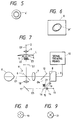
- the measuring light source 2 When the refractive power of the lens L to be examined is measured, the measuring light source 2 is turned on while bringing the lens L to be examined into contact with the holding member 5. The beam emitted from the measuring light source 2 is made to be a collimated beam by the lens 3. The collimated beam is then incident upon the lens L to be examined, and is transmitted and refracted. Then, the transmitted and refracted beam passes through the dichroic mirror 6 via the diaphragm 4 so that five refracted beams M are projected to the surface of the imaging element 8 as shown in Fig. 3. The information about the positions of the beams M are converted into video signals by the imaging means 9 and is transmitted to the signal treating means 10.
- the refractive power of the lens L to be examined can be calculated in the measuring part 1 for the eye refractive power from said positional relationship.
- the lens L to be examined can easily be aligned by an examiner in such a manner that a mark T is previously electrically generated at the position of the optical axis 02 on the imaging element 8 and a central beam M0 is, by the examiner, aligned with the mark T while observing the imaging element 8.
- At least three apertures must be formed in the diaphragm 4 in addition to the central aperture for establishing the alignment with the mark T, so that the refractive power can be calculated.
- the diaphragm 4 may be replaced by a diaphragm 4' having, as shown in Fig. 5, an annular aperture.
- beam M' as shown in Fig. 6 is formed on the imaging element 8.
- the shape of the thus formed annular beam M' is used to calculate the refractive power, and the alignment is performed in such a manner that the center of the beam M' is aligned with the optical axis 02.
- Fig. 7 is a structural view which illustrates a second embodiment of the apparatus according to the present invention, where the same reference numerals as those shown in the above-described embodiment represent the same elements.
- the dichroic mirror 6, the lens 7, a dichroic mirror 12 and the imaging element 8 on the optical axis 01 which substantially coincides with a glance of the eye E to be examined.
- the output from the imaging element 8 is connected to the imaging means 9, while the output from the imaging means 9 is connected to the signal treating means 10.
- a measuring light source 13 is provided.
- a lens 14 On an optical axis 03 established from the measuring light source 13 to the eye E to be examined, a lens 14, a central aperture 15, a mirror 16 having an aperture, a mirror 17 arranged to reflect light into a direction which is made coincide with the optical axis. Furthermore, a lens 18 is disposed on the optical axis 02. On an optical axis 04 established in the direction into which the mirror 16 having an aperture reflects light, there are disposed a 4-aperture diaphragm 19 having, as shown in Fig. 8, four apertures, a lens 20 and a separation prism 21 composed of four wedge prisms as shown in Fig. 9.
- a lens 22 and another separation prism 23 having the same structure as that of the separation prism 21 are, in this sequential order, disposed on the optical axis 02 established between a group of elements disposed on the optical axis 02 and the dichroic mirror 6, the group being consisting of the measuring light source 2, the lens 3, the diaphragm 4 and the holding member 5.
- the dichroic mirror 6 has spectrum characteristics with which it reflects infrared rays emitted from the measuring light sources 2 and 13 and transmits a beam emitted from the illuminating light source 11.
- the dichroic mirror 12 has spectrum characteristics with which it transmits a beam emitted from the illuminating light source 11 and reflects the infrared ray emitted from the measuring light source 13.
- the illuminating light source 11 When the refractive power of the eye E to be examined is measured with the apparatus thus structured, the illuminating light source 11 is first turned on so that the eye E to be examined is radiated by the beam emitted from the illuminating light source 11. The beam reflected at the anterior eye portion passes through the dichroic mirror 6 and through the lens 7 and the dichroic mirror 12, and then the image of the anterior eye portion is formed on the imaging element 8.
- the illuminating light source 11 When the refractive power of the eye E to be examined is measured, the illuminating light source 11 is turned off but the measuring light source 13 is turned on.
- the beam emitted from the measuring light source 13 passes along the optical axis 03 in such a manner that it passes through the lens 14, the central aperture diaphragm 15 and the mirror 16 having an aperture before it is reflected by the mirror 17. Then, it passes through the lens 18 before it is reflected by the dichroic mirror 6. As a result, it reaches to the eye E to be examined.
- the beam reflected at the eye fundus of the eye E to be examined returns along the same optical path in such a manner that it is reflected by the mirror 16 having an aperture before it passes through the 4-aperture diaphragm 19 and the lens 20.
- the four beams are imaged on the imaging element 8 so that the positions of the beams are, similarly to the first embodiment, imaged by the imaging means 9. Consequently, the refractive power of the eye E to be examined is calculated in the signal treating means 10.
- the measuring light source 2 when the refractive power of the lens L to be examined is measured, the measuring light source 2 is turned on. The beam emitted from the measuring light source 2 passes through the lens 3 before it is refracted by the lens L to be examined. Then, it passes through the diaphragm 4 and the lens 22 before it is separated from the optical axis 02 by the separation prism 23. Subsequently, it is reflected by the dichroic mirror 6 before it passes through the lens 7 and the dichroic mirror 12. As a result, the four beams are imaged on the imaging element 8 so that the refractive power is, similarly to the above-described cases, calculated from the positioned relationship between the four beams.
- the imaging element 8 for observing the anterior eye portion of the eye E to be examined is also used to measure the refractive power of the lens L to be examined. Furthermore, the imaging element 8 and the lens L to be examined have a non-conjugated relationship. If the structure is arranged in such a manner that the beam refracted by the lens L to be examined is introduced into the four-aperture diaphragm 19, the lens 20 and the separation prism 21 for use to measure the refractive power of the eye E to be examined, the diaphragm 4, the lens 22 and the separation prism 23 can be omitted from the structure.
- the refractometer according to this embodiment is arranged in such a manner that the holding member for holding the lens to be examined is disposed at the non-conjugated position with respect to the position of the imaging means for imaging the anterior eye portion of the eye to be examined.
- the beam is projected to the lens to be examined which has been holded as described above.
- the beam refracted by the lens to be examined is introduced into the imaging means so that the refractive power is measured from the refracted beams formed on the imaging means.
- the imaging means for observing the anterior eye portion of the eye to be examined is also used to measure the refractive power, so that the structure of the refractometer can be simplified.
- the lens to be examined can easily be aligned by the examiner since the examiner observes the positions of the refracted beams formed on the imaging means. Therefore, excellent operation facility is realized if it is used as a lens meter.
- Fig. 10 is a structural view which illustrates a third embodiment of the present invention.
- an eye measuring light source 31 which as well as serves as an index for the measurement, is disposed for the purpose of measuring the refractive power of the eye E to be examined.
- the light source 31 for measuring the eye E to be examined is disposed in substantially conjugation with the eye fundus Er of the eye E to be examined, the projecting diaphragm 33 and the measuring diaphragm 37 are disposed in conjugation with the pupil Ei and the mirror 34 having an aperture is disposed in substantially conjugation with the pupil Ei.
- a lens measuring light source 43 which is arranged to as well as serve as a measuring index, is disposed.
- a lens 44 On the optical path 03 established from the lens measuring light source 43 to the dichroic mirror 36, there are disposed a lens 44, a holding member 45 for holding the lens G to be examined, a measuring diaphragm 46 having six aperture similarly to the measuring diaphragm 37 and a reflecting mirror 47.
- one or more illuminating light sources 48 are disposed to confront the eye E to be examined.
- a reflecting mirror 49 is disposed on the optical path 04 established in a direction along which light passes from the eye E to the dichroic mirror 36.
- a lens 50 and a filter 51 are disposed in a direction into which light is reflected by the reflecting mirror 49.
- the lens measuring light source 43 emits a visible ray having wavelength of which is about 550 nm, while the illuminating light source 48 emits an infrared ray having wavelength of which is about 760 nm.
- a filter 51 is composed of a filter 51a having a transmission characteristic as shown in Fig. 14A (that is, only light emitted from the illuminating light source 48 is transmitted) and a filter 51b having a transmission characteristic as shown in Fig. 14B (that is, only light emitted from the measuring light source 43 is transmitted).
- a driving means acts to selectively place the filter 51a or the filter 51b to the optical path.
- the dichroic mirror 36 has spectrum characteristics with which it transmits the infrared rays emitted from the illuminating light source 48 and reflects the beam emitted from the lens measuring light source 43.
- the dichroic mirror 40 has spectrum characteristics with which it transmits the beam emitted from the light source 31 for measuring the eye E to be examined and reflects the beams respectively emitted from the lens measuring light source 43 and the illuminating light source 48.
- the illuminating light source 48 is first turned on in a state that the filter 51a has been placed on the optical path 04, so that the anterior eye portion of the eye E to be examined is irradiated with the beam emitted from the illuminating light source 48.
- the beam reflected by the anterior eye portion passes through the dichroic mirror 36 before it travels along the optical path 04.
- An examiner subsequently performs the alignment operation while observing the above-described image M of the anterior eye portion. Then, the illuminating light source 48 is turned off after the alignment has been ended. Subsequently, the light source 31 for measuring the eye E to be examined is turned on. The beam emitted from the measuring light source 31 travels along the optical path 01 in such a manner that it passes through the lens 32, the projecting diaphragm 33, the aperture portion of the mirror 34 having an aperture and the lens 35 before it is reflected by the dichroic mirror 36. Thus, it reaches to the eye E to be examined. The beam reflected from the eye fundus Er returns along the same optical path before it is reflected by the mirror 34 having an aperture.
- the refractive power of the eye E to be examined can be calculated from the positional relationship between the reflected beam images P.
- the lens measuring light source 43 When the lens G to be examined is measured, only the lens measuring light source 43 is turned on in a state that the lens G to be examined has been brought into contact with the holding member 45 so as to be fixed on the optical path 03 and as well as the filter 51b has been inserted into the optical path 04.
- the beam emitted from the lens measuring light source 43 is made to be a collimated beam by the lens 44.
- the collimated beam is then incident upon the lens G to be examined. Then, it is reflected by the reflecting mirror 47, the dichroic mirror 36 and the reflecting mirror 49 via the measuring diaphragm 46. Subsequently, it passes through the lens 50 and the filter 51b before it is reflected by the dichroic mirror 40. As a result, it is projected on the imaging element 41 as the six transmitted beam images similarly to those shown in Fig. 16. Therefore, the refractive power and the prismatic effect of the lens G to be examined can be calculated from the positional relationship between the transmitted beam images.
- the filter 51a is inserted into the optical path 04 when the anterior eye portion is observed. Therefore, the beam from, for example, the room light can be shielded by the filter 51a so that the image M of the anterior eye portion can be clearly displayed on the TV monitor 42.
- the filter 51b is inserted. Therefore, the beam from, for example, the room light is shielded by the filter 51b so that the transmitted beam images can be cleared and the refractive power can thereby be measured accurately.
- the alignment operation for aligning the optical axis of the lens G to be examined with the optical path 03 can be performed by utilizing the positions of the transmitted beam images of the lens G to be examined. For example, it can be easily performed in such a manner that a radial mark Q as shown in Fig. 17 is electrically generated on the TV monitor 42 and a transmitted beam image P' from the lens G to be examined is output to the TV monitor 42 so as to align the center of the transmitted beam image P' with the center of the mark Q.
- the filter 51 is disposed between the lens 50 and the dichroic mirror 40 according to the above-described embodiment, another structure may be empoloyed which is arranged in such a manner that the filters 51a and 51b are selectively inserted into the individual positions in the optical path 04 established from the dichroic mirror 36 to the dichroic mirror 40.
- the beam emitted from the lens measuring light source 43 or the illuminating light source 48 is not limited to the above-described wavelength. Any beam included in the infrared ray region or the visible ray region may be employed if they can be separated. In this state, the filter 51a or 51b, which corresponds to the selected beam, may be used.
- Fig. 18 is a structural view which illustrates a fourth embodiment of the present invention.
- the optical system for measuring the refractive power of the eye E to be examined and the optical system for observing the anterior eye portion are similarly arranged to those according to the embodiment shown in Fig. 10.
- a dichroic mirror 52 is disposed and a filter 51a' is disposed between the dichroic mirrors 52 and 36.
- a filter 51b' is detachably disposed between the lens 50 and the dichroic mirror 40.
- the dichroic mirror 52 has spectrum characteristics with which it transmits the beam emitted from the illuminating light source 48 and reflects the beam emitted from the lens measuring light source 43.
- the transmission characteristic of the filter 51a' or the filter 51b' is arranged to be the same as that of the filter 51a or the filter 51b shown in Fig. 10.
- the filter 51b' is retracted from the optical path so as to radiate the beam emitted from the illuminating light source 48 to the anterior eye portion of the eye E to be examined.
- the beam reflected by the anterior eye portion passes through the dichroic mirror 36, the filter 51a and the dichroic mirror 52 before it is reflected by the reflecting mirror 49. Then, it is reflected by the dichroic mirror 40 via the lens 50 before it is projected to the surface of the imaging element 42. As a result, the image M of the anterior eye portion is displayed on the TV monitor 42.
- the lens measuring light source 43 When the refractive power of the lens G to be examined is measured, the lens measuring light source 43 is turned on in a state that the filter 51b' has been placed on the optical path and the lens G to be examined has been brought into contact with the holding member 45.
- the beam emitted from the measuring light source 43 travels along the optical path 03 and passes through the lens 44, the lens G to be examined and the measuring diaphragm 46. Then, it is reflected by the reflecting mirror 47, the dichroic mirror 52 and the reflecting mirror 49 before it passes through the lens 50 and the filter 51b'. Then, it is reflected by the dichroic mirror 40 before the transmitted beam images are formed on the imaging element 41.
- the refractive power can be calculated from the positions of the transmitted beam images.
- the effects of the filters 51a' and 51b' are the same as those according to the above-described embodiments.
- the ophthalmological measuring apparatus is arranged in such a manner that the optical position detecting sensor is used to observe the anterior eye portion as well as to measure the refractive power of the eye to be examined and the lens to be examined. Furthermore, the wavelength of the beam for observing the anterior eye portion and that of the beam for measuring the refractive power of the lens to be examined are separated from each other.
- the optical member which transmits only a predetermined wavelength region including the wavelength of the beam for observing the anterior eye portion, is inserted into the optical system for observing the anterior eye portion.
- the optical member which transmits only a predetermined wavelength region including the wavelength of the beam for measuring the lens to be examined, is inserted into the optical system for measuring the refractive power of the lens to be examined. Therefore, the refractive power of the eye to be examined and that of the lens to be examined can be accurately measured while reducing the cost of the overall apparatus and simplifying the overall structure.
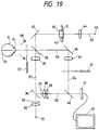
- Fig. 19 is a structural view which illustrates a fifth embodiment of the present invention, where the same reference numerals as those according to the above-described embodiments represent the same elements.
- One or more illuminating light sources 48 for observing the anterior eye of the eye E are disposed to confront the eye E to be examined.
- the dichroic mirror 36 On the optical path rectilinearly extending from the eye E to be examined to the dichroic mirror 36, the reflecting mirror 49, the lens 50 and the detachable light insulating plate 51 are disposed.
- the light shielding plate 57 is retracted from the optical path 01 and the light shielding plate 51 is also retracted from the optical path 04. Then, the illuminating light source 48 is turned on so as to radiate light to the anterior eye portion.
- the beam reflected from the anterior eye portion of the eye E to be examined passes through the dichroic mirror 36 before it is reflected by the reflecting mirror 49. Then, it is reflected by the dichroic mirror 40 via the lens 50. As a result, it is imaged as the image M of the anterior eye portion on the imaging element 41.
- the image M of the anterior eye portion is, as shown in Fig. 15, displayed on the TV monitor 13.
- the light shielding plate 51 is inserted into the optical path 04 in a state that the light shielding plate 57 has been retracted from the optical path 01.
- the lens measuring light source 43 When the refractive power of the lens G to be examined is measured, the lens measuring light source 43 is turned on in a state that the lens G to be examined has been brought into contact with the holding member 45 so as to be fixed, the light shielding plate 57 has been inserted into the optical path 01 and the light shielding plate 51 has been retracted from the optical path 04.
- the alignment operation to align the optical axis of the lens G to be examined with the optical path 03 can be performed by utilizing the position of the reflected beam P' on the imaging element 41.
- the lens G to be examined can be aligned in such a manner that a radial mark Q as shown in Fig. 20 is electrically generated on the TV monitor 42.
- a reflected beam P' is transmitted to the TV monitor 42 so as to align the center of the transmitted beam P' with the center of the mark Q.
- the reason why the light shielding plate 57 is used at this measurement operation lies in the fact that the refractive power can only be accurately measured if it is prevented that the beam emitted from, for example, a room light is received by the imaging element 41 after it has been reflected by, for example, the face of an examiner.
- the diaphragm 46 and the reflecting mirror 47 are omitted from the elements disposed on the optical path 03 shown in Fig. 19. In this state, the beam travels along the optical axis 01 so as to pass through the diaphragm 37.
- Fig. 22 is a structural view which illustrates a seventh embodiment of the present invention.
- a detachable reflecting mirror 62, a dichroic mirror 63 and a light shielding plate 57 which can be inserted/retracted from the optical path 05, are disposed on the optical path 05 extending from the light source 31 for measuring the eye E to be examined to the eye E.
- the reflecting mirror 49 is disposed, while the lens 50, the light shielding plate 51, which can be inserted/retracted from the optical path and a dichroic mirror 65 are disposed in a direction into which a beam is reflected at the reflecting mirror 49.
- the reflecting mirror 62 is inserted into the optical path 05 or retracted from the same when it is used.
- the reflecting mirror 62 is retracted from the optical path 05 and the illuminating light source 48 for use to observe the anterior eye portion is turned on so that the anterior eye portion is irradiated with light.
- the beam reflected from the anterior eye portion is reflected by the dichroic mirror 63 and the reflecting mirror 49. Furthermore, it is reflected by the dichroic mirror 65 via the lens 50 so that it is projected to the surface of the imaging element 41 as the image M of the anterior eye portion.
- the thus formed image M of the anterior eye portion is transmitted to the TV monitor 42.
- the display formed on the TV monitor 42 is observed by an examiner to perform the alignment.
- the illuminating light source 48 is turned off and the light source 31 for measuring the eye E to be examined is turned on.
- the light insulating plates 51 and 57 act as those according to the embodiment shown in Fig. 21.
- Fig. 23 is a structural view which illustrates an eighth embodiment of the present invention.
- two relay lenses 66 and 67 are disposed between the holding member 45 and the reflecting mirror 47 disposed on the optical path 03.
- the other structure is the same as that according to the above-described embodiments.
- the lens G to be examined can be positioned suitably for the operation by properly determining the focal distance of each of the relay lenses 66 and 67.
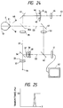
- Fig. 24 is a structural view which illustrates a ninth embodiment of the present invention.
- the optical system for measuring the refractive power of the eye E to be examined and the optical system for observing the anterior eye portion are similarly arranged to those according to the above-described embodiments.
- the ninth embodiment is arranged in such a manner that the dichroic mirror 36a has a characteristic as shown in Fig. 25, with which only the wavelength of the beam emitted from the illuminating light source 48, as shown in Fig. 25, is transmitted by a quantity of about 50%.
- the wavelength of the beam emitted from the light source 43 for measuring the refractive power of the lens G to be examined is the same as that emitted from the light source 48.
- the beam emitted from the above-described light source 43 is reflected by the dichroic mirror 36a before it passes through the mirror 49, the lens 50 and the dichroic mirror 40. As a result, it reaches to the imaging element.
- the dichroic mirror 36a considerably reduces disturbance light which passes through the optical path 03 and made incident upon the imaging element 41.
- the transmittance may, of course, be set to a value other than 50% if the influence of the disturbance or the like can be eliminated.
Landscapes
- Life Sciences & Earth Sciences (AREA)
- Health & Medical Sciences (AREA)
- Medical Informatics (AREA)
- Biophysics (AREA)
- Ophthalmology & Optometry (AREA)
- Engineering & Computer Science (AREA)
- Biomedical Technology (AREA)
- Heart & Thoracic Surgery (AREA)
- Physics & Mathematics (AREA)
- Molecular Biology (AREA)
- Surgery (AREA)
- Animal Behavior & Ethology (AREA)
- General Health & Medical Sciences (AREA)
- Public Health (AREA)
- Veterinary Medicine (AREA)
- Eye Examination Apparatus (AREA)
Claims (12)
- Appareil ophtalmologique comportant :
un système (11, 48) d'observation d'alignement ayant un premier moyen capteur de lumière qui est sensiblement en conjugaison avec une partie antérieure d'un oeil (E) à examiner ;
un système (1) de mesure de la puissance de réfraction de l'oeil ayant une première source de lumière (13, 31) destinée à projeter un faisceau lumineux sur le fond (Er) de l'oeil (E) à examiner et agencé pour mesurer la puissance de réfraction de l'oeil en recevant un faisceau lumineux réfléchi au fond (Er) de l'oeil à l'aide d'un second moyen capteur de lumière (41) ;
des moyens (5, 45) destinés à porter une lentille (L, G) à examiner dans une position qui est différente d'une position dans laquelle l'oeil (E) à examiner est placé ; et
un système de mesure de la puissance de réfraction de la lentille ayant une seconde source de lumière (2, 43) destinée à projeter un faisceau lumineux sur la lentille (R, G) à examiner et agencé de façon à mesurer la puissance de réfraction de la lentille en recevant ledit faisceau lumineux qui est passé à travers ladite lentille (L, G), à l'aide d'un troisième moyen capteur de lumière (8),
dans lequel ladite première source de lumière (13, 31) et ladite seconde source de lumière (2, 43) sont différentes l'une de l'autre et ledit troisième moyen capteur de lumière et au moins l'un dudit premier moyen capteur de lumière et dudit second moyen capteur de lumière sont constitués par un dispositif capteur de lumière commun. - Appareil ophtalmologique selon la revendication 1, dans lequel ledit troisième moyen capteur de lumière (8) est non conjugué avec une position dans laquelle ladite lentille (L, G) à examiner est placée.
- Appareil ophtalmologique selon la revendication 1, dans lequel lesdits premier, deuxième et troisième moyens capteurs de lumière sont composés d'un dispositif capteur de lumière commun (8).
- Appareil ophtalmologique selon la revendication 1, dans lequel ledit système d'observation d'alignement comporte un moniteur (42) d'affichage qui est connecté audit dispositif capteur de lumière commun (41), ledit moniteur d'affichage (42) ayant un repère (Q) de positionnement formé sur une partie prédéterminée de ce moniteur.
- Appareil ophtalmologique selon la revendication 1, dans lequel ledit système d'observation d'alignement comporte une source de lumière (11, 48) destinée à éclairer la partie antérieure de l'oeil.
- Appareil ophtalmologique selon la revendication 1, dans lequel ledit système de mesure de la puissance de réfraction de la lentille comporte un système optique relais (66, 67) entre ledit troisième moyen capteur de lumière et ledit moyen (45) destiné à porter ladite lentille (G) à examiner.
- Appareil ophtalmologique selon la revendication 5, dans lequel au moins une partie d'un chemin optique (01, 04) pour ledit système (1) de mesure de la puissance de réfraction de la lentille est utilisée en commun par ledit système d'observation d'alignement.
- Appareil ophtalmologique selon la revendication 7, comportant en outre des moyens (51, 57, 51a', 51b') de sélection de lumière destinés à sélectionner soit un faisceau lumineux émis par ladite source de lumière (48) pour éclairer ladite partie antérieure de l'oeil, soit un faisceau lumineux émis par ladite seconde source de lumière (43).
- Appareil ophtalmologique selon la revendication 8, dans lequel ledit moyen de sélection de lumière est un filtre (51, 51a', 51b') de sélection de longueur d'onde.
- Appareil ophtalmologique selon la revendication 8, dans lequel ledit moyen de sélection de lumière est une plaque (51, 57) d'écran à la lumière qui peut être insérée dans un chemin optique ou rétractée de ce chemin optique, librement.
- Appareil ophtalmologique selon la revendication 1, dans lequel ledit système d'observation d'alignement comporte un moniteur d'affichage (42) qui est utilisé pour observer l'alignement dudit système de mesure de la puissance de réfraction de l'oeil ainsi que l'alignement dudit système de mesure de la puissance de réfraction de la lentille.
- Appareil ophtalmologique selon la revendication 5, comportant en outre un moyen (36a) de sélection de longueur d'onde destiné à relier le chemin optique dudit système de mesure de la puissance de réfraction de la lentille au chemin optique dudit système d'observation d'alignement, permettant à une longueur d'onde de lumière émise par ladite seconde source de lumière (43) d'être la même que celle de la lumière émise par ladite source de lumière (48) pour éclairer la partie antérieure de l'oeil, et transmettant uniquement la lumière de ladite longueur d'onde le long du chemin optique dudit système d'observation d'alignement.
Applications Claiming Priority (8)
| Application Number | Priority Date | Filing Date | Title |
|---|---|---|---|
| JP112909/90 | 1990-04-27 | ||
| JP2112909A JPH0761312B2 (ja) | 1990-04-27 | 1990-04-27 | 眼屈折計 |
| JP2128388A JPH0422330A (ja) | 1990-05-18 | 1990-05-18 | 眼科用測定装置 |
| JP128388/90 | 1990-05-18 | ||
| JP2143457A JPH0761313B2 (ja) | 1990-06-01 | 1990-06-01 | 眼科用測定装置 |
| JP156969/90 | 1990-06-15 | ||
| JP2156969A JPH0449942A (ja) | 1990-06-15 | 1990-06-15 | 眼科用測定装置 |
| JP143457/90 | 1991-06-14 |
Publications (2)
| Publication Number | Publication Date |
|---|---|
| EP0454154A1 EP0454154A1 (fr) | 1991-10-30 |
| EP0454154B1 true EP0454154B1 (fr) | 1995-08-09 |
Family
ID=27470040
Family Applications (1)
| Application Number | Title | Priority Date | Filing Date |
|---|---|---|---|
| EP91106820A Expired - Lifetime EP0454154B1 (fr) | 1990-04-27 | 1991-04-26 | Appareil ophtalmique |
Country Status (3)
| Country | Link |
|---|---|
| US (1) | US5144346A (fr) |
| EP (1) | EP0454154B1 (fr) |
| DE (1) | DE69111876T2 (fr) |
Families Citing this family (21)
| Publication number | Priority date | Publication date | Assignee | Title |
|---|---|---|---|---|
| JPH0647003A (ja) * | 1992-01-08 | 1994-02-22 | Canon Inc | 眼科装置 |
| JPH0646995A (ja) * | 1992-07-30 | 1994-02-22 | Canon Inc | 眼屈折計 |
| US6079830A (en) * | 1992-08-31 | 2000-06-27 | Canon Kabushiki Kaisha | Eye measuring apparatus having signal processing means for calculating eye information |
| US5777718A (en) * | 1992-12-31 | 1998-07-07 | Canon Kabushiki Kaisha | Eye refractometer |
| JP3016499B2 (ja) * | 1993-06-03 | 2000-03-06 | キヤノン株式会社 | 角膜形状測定装置 |
| JP3359100B2 (ja) * | 1993-06-29 | 2002-12-24 | キヤノン株式会社 | 検眼装置 |
| US5847805A (en) * | 1993-07-12 | 1998-12-08 | Canon Kabushiki Kaisha | Scan imaging device for forming a stereoscopic image of the eye |
| JP3376069B2 (ja) * | 1993-12-30 | 2003-02-10 | キヤノン株式会社 | 眼科装置 |
| JP3450403B2 (ja) * | 1994-01-28 | 2003-09-22 | キヤノン株式会社 | 検眼装置 |
| US5675399A (en) * | 1994-04-30 | 1997-10-07 | Canon Kabushiki Kaisha | Ophthalmic apparatus |
| US5825460A (en) * | 1994-04-30 | 1998-10-20 | Canon Kabushiki Kaisha | Visual function measuring apparatus |
| US6304723B1 (en) | 1994-10-11 | 2001-10-16 | Canon Kk | Retinal camera |
| JP3507183B2 (ja) * | 1995-03-24 | 2004-03-15 | キヤノン株式会社 | 眼屈折計 |
| DE29618443U1 (de) * | 1996-10-22 | 1996-12-12 | G. Rodenstock Instrumente GmbH, 85521 Ottobrunn | Scheitelbrechwertmesser |
| RU2148945C1 (ru) * | 1997-12-10 | 2000-05-20 | Межотраслевой научно-технический комплекс "Микрохирургия глаза" | Устройство для определения кривизны роговицы и ее коэффициента преломления |
| JPH11211617A (ja) | 1998-01-22 | 1999-08-06 | Topcon Corp | レンズ特定装置 |
| JP2001231752A (ja) | 2000-02-24 | 2001-08-28 | Canon Inc | 検眼装置 |
| JP3401502B2 (ja) * | 2000-07-13 | 2003-04-28 | 松下電器産業株式会社 | 目画像撮像装置 |
| WO2002014827A1 (fr) * | 2000-08-11 | 2002-02-21 | Kabushiki Kaisha Topcon | Dispositif de mesure de refraction |
| JP5210442B1 (ja) | 2012-01-26 | 2013-06-12 | キヤノン株式会社 | 光断層撮像装置および制御方法 |
| JP5210443B1 (ja) | 2012-01-26 | 2013-06-12 | キヤノン株式会社 | 光断層撮像装置および制御方法 |
Family Cites Families (8)
| Publication number | Priority date | Publication date | Assignee | Title |
|---|---|---|---|---|
| US3832066A (en) * | 1972-10-27 | 1974-08-27 | Acuity Syst Inc | Apparatus and method for analyzing sphero-cylindrical optical systems |
| US4275964A (en) * | 1979-05-18 | 1981-06-30 | Rodenstock Instruments Corporation | Apparatus and method for determining the refractive characteristics of a test lens |
| US4609287A (en) * | 1982-10-05 | 1986-09-02 | Canon Kabushiki Kaisha | Method of and apparatus for measuring refractive characteristics |
| JPS61320A (ja) * | 1984-06-12 | 1986-01-06 | キヤノン株式会社 | 自動視力計 |
| US4761070A (en) * | 1984-12-07 | 1988-08-02 | Tokyo Kogaku Kikai Kabushiki Kaisha | Eye refractometer |
| US4820037A (en) * | 1985-01-10 | 1989-04-11 | Canon Kabushiki Kaisha | Apparatus for measuring the refractive power of an eye |
| US4826315A (en) * | 1985-06-14 | 1989-05-02 | Canon Kabushiki Kaisha | Lens meter |
| JPS6353433A (ja) * | 1986-08-23 | 1988-03-07 | Canon Inc | 眼・レンズ屈折度測定装置 |
-
1991
- 1991-04-26 DE DE69111876T patent/DE69111876T2/de not_active Expired - Fee Related
- 1991-04-26 EP EP91106820A patent/EP0454154B1/fr not_active Expired - Lifetime
- 1991-04-26 US US07/691,782 patent/US5144346A/en not_active Expired - Lifetime
Also Published As
| Publication number | Publication date |
|---|---|
| US5144346A (en) | 1992-09-01 |
| DE69111876D1 (de) | 1995-09-14 |
| DE69111876T2 (de) | 1995-12-21 |
| EP0454154A1 (fr) | 1991-10-30 |
Similar Documents
| Publication | Publication Date | Title |
|---|---|---|
| EP0454154B1 (fr) | Appareil ophtalmique | |
| US3524702A (en) | Apparatus for objectively and automatically refracting the eye | |
| US4848896A (en) | Eye refractometer | |
| EP0229662B1 (fr) | Appareil de microscopie chirurgicale | |
| JPS6153052B2 (fr) | ||
| JPS6324927A (ja) | 眼科測定装置 | |
| JP2632436B2 (ja) | オートレンズメータ | |
| US5420650A (en) | Eye examining apparatus including an eye refraction measuring system and eye fundus examining system | |
| US5371558A (en) | Ophthalmic apparatus | |
| US5781275A (en) | Eye refractometer and eye refractive power measuring apparatus for electro-optically measuring the refractive power of the eye | |
| JPS60253429A (ja) | 眼科検査装置 | |
| US4364646A (en) | Position adjusting device for ophthalmologic instrument | |
| JP3672261B2 (ja) | 観察者の眼により見た視野部分を決定する装置 | |
| JP2945092B2 (ja) | 眼屈折計 | |
| JPH0430854B2 (fr) | ||
| JP3015042B2 (ja) | 手持ち眼屈折計 | |
| JPH049135A (ja) | 眼屈折計 | |
| JP2951991B2 (ja) | 眼屈折計 | |
| JPS62288806A (ja) | 実体顕微鏡 | |
| JPH0473040A (ja) | 眼科測定装置 | |
| JPH0397436A (ja) | 角膜形状測定装置 | |
| JPH03297441A (ja) | 眼屈折計 | |
| JPH0571247B2 (fr) | ||
| JPH0435638A (ja) | 眼科用測定装置 | |
| JPH0422330A (ja) | 眼科用測定装置 |
Legal Events
| Date | Code | Title | Description |
|---|---|---|---|
| PUAI | Public reference made under article 153(3) epc to a published international application that has entered the european phase |
Free format text: ORIGINAL CODE: 0009012 |
|
| AK | Designated contracting states |
Kind code of ref document: A1 Designated state(s): DE ES FR IT |
|
| 17P | Request for examination filed |
Effective date: 19920316 |
|
| 17Q | First examination report despatched |
Effective date: 19940323 |
|
| GRAA | (expected) grant |
Free format text: ORIGINAL CODE: 0009210 |
|
| AK | Designated contracting states |
Kind code of ref document: B1 Designated state(s): DE ES FR IT |
|
| PG25 | Lapsed in a contracting state [announced via postgrant information from national office to epo] |
Ref country code: IT Free format text: LAPSE BECAUSE OF FAILURE TO SUBMIT A TRANSLATION OF THE DESCRIPTION OR TO PAY THE FEE WITHIN THE PRE;WARNING: LAPSES OF ITALIAN PATENTS WITH EFFECTIVE DATE BEFORE 2007 MAY HAVE OCCURRED AT ANY TIME BEFORE 2007. THE CORRECT EFFECTIVE DATE MAY BE DIFFERENT FROM THE ONE RECORDED.SCRIBED TIME-LIMIT Effective date: 19950809 Ref country code: ES Free format text: THE PATENT HAS BEEN ANNULLED BY A DECISION OF A NATIONAL AUTHORITY Effective date: 19950809 |
|
| REF | Corresponds to: |
Ref document number: 69111876 Country of ref document: DE Date of ref document: 19950914 |
|
| ET | Fr: translation filed | ||
| PLBE | No opposition filed within time limit |
Free format text: ORIGINAL CODE: 0009261 |
|
| STAA | Information on the status of an ep patent application or granted ep patent |
Free format text: STATUS: NO OPPOSITION FILED WITHIN TIME LIMIT |
|
| 26N | No opposition filed | ||
| PGFP | Annual fee paid to national office [announced via postgrant information from national office to epo] |
Ref country code: DE Payment date: 20070419 Year of fee payment: 17 |
|
| PGFP | Annual fee paid to national office [announced via postgrant information from national office to epo] |
Ref country code: FR Payment date: 20070411 Year of fee payment: 17 |
|
| PG25 | Lapsed in a contracting state [announced via postgrant information from national office to epo] |
Ref country code: DE Free format text: LAPSE BECAUSE OF NON-PAYMENT OF DUE FEES Effective date: 20081101 |
|
| REG | Reference to a national code |
Ref country code: FR Ref legal event code: ST Effective date: 20081231 |
|
| PG25 | Lapsed in a contracting state [announced via postgrant information from national office to epo] |
Ref country code: FR Free format text: LAPSE BECAUSE OF NON-PAYMENT OF DUE FEES Effective date: 20080430 |