EP0454368B1 - Installation de diversité adaptative pour systèmes téléphoniques mobiles cellulaires - Google Patents
Installation de diversité adaptative pour systèmes téléphoniques mobiles cellulaires Download PDFInfo
- Publication number
- EP0454368B1 EP0454368B1 EP91303508A EP91303508A EP0454368B1 EP 0454368 B1 EP0454368 B1 EP 0454368B1 EP 91303508 A EP91303508 A EP 91303508A EP 91303508 A EP91303508 A EP 91303508A EP 0454368 B1 EP0454368 B1 EP 0454368B1
- Authority
- EP
- European Patent Office
- Prior art keywords
- receiver
- signal
- mode
- receivers
- received signal
- Prior art date
- Legal status (The legal status is an assumption and is not a legal conclusion. Google has not performed a legal analysis and makes no representation as to the accuracy of the status listed.)
- Expired - Lifetime
Links
- 230000003044 adaptive effect Effects 0.000 title claims description 11
- 230000001413 cellular effect Effects 0.000 title claims description 7
- 238000004891 communication Methods 0.000 claims description 24
- 238000000034 method Methods 0.000 claims description 17
- 238000012545 processing Methods 0.000 claims description 16
- 230000000737 periodic effect Effects 0.000 claims description 11
- 238000012546 transfer Methods 0.000 claims description 9
- 230000001902 propagating effect Effects 0.000 claims description 7
- 230000005236 sound signal Effects 0.000 claims description 5
- 238000005259 measurement Methods 0.000 description 16
- 238000005562 fading Methods 0.000 description 11
- 238000013461 design Methods 0.000 description 5
- 238000010586 diagram Methods 0.000 description 4
- 230000000694 effects Effects 0.000 description 4
- 230000005540 biological transmission Effects 0.000 description 3
- 230000002860 competitive effect Effects 0.000 description 3
- 230000001419 dependent effect Effects 0.000 description 3
- 238000005070 sampling Methods 0.000 description 3
- 230000008901 benefit Effects 0.000 description 2
- 239000013065 commercial product Substances 0.000 description 2
- 239000007787 solid Substances 0.000 description 2
- 238000001514 detection method Methods 0.000 description 1
- 230000002452 interceptive effect Effects 0.000 description 1
- 238000012986 modification Methods 0.000 description 1
- 230000004048 modification Effects 0.000 description 1
- 239000000047 product Substances 0.000 description 1
- 238000005096 rolling process Methods 0.000 description 1
Images


Classifications
-
- H—ELECTRICITY
- H04—ELECTRIC COMMUNICATION TECHNIQUE
- H04B—TRANSMISSION
- H04B7/00—Radio transmission systems, i.e. using radiation field
- H04B7/02—Diversity systems; Multi-antenna system, i.e. transmission or reception using multiple antennas
- H04B7/04—Diversity systems; Multi-antenna system, i.e. transmission or reception using multiple antennas using two or more spaced independent antennas
- H04B7/08—Diversity systems; Multi-antenna system, i.e. transmission or reception using multiple antennas using two or more spaced independent antennas at the receiving station
- H04B7/0802—Diversity systems; Multi-antenna system, i.e. transmission or reception using multiple antennas using two or more spaced independent antennas at the receiving station using antenna selection
- H04B7/0817—Diversity systems; Multi-antenna system, i.e. transmission or reception using multiple antennas using two or more spaced independent antennas at the receiving station using antenna selection with multiple receivers and antenna path selection
- H04B7/082—Diversity systems; Multi-antenna system, i.e. transmission or reception using multiple antennas using two or more spaced independent antennas at the receiving station using antenna selection with multiple receivers and antenna path selection selecting best antenna path
Definitions
- the invention relates to improvements in cellular telephone base stations.
- Contemporary cellular mobile telephone systems conventionally include a "diversity" system of some nature in the base or fixed station receivers to reduce the effects of multipath fading wherein large rapid fluctuations of signal level occur.
- the signals received by two or more antennas are normally made available to the receiving equipment and a process or scheme is provided whereby when the signal from one antenna is experiencing a large negative fluctuation or deep fade the signal from another antenna may be substituted.
- Such switching thus produces a signal level of higher average signal strength, and the quality of communications is inherently improved.
- FIG. 1 is a simplified block diagram illustrating a single channel.
- each antenna conventionally may serve many channels through a multicoupler.
- multicouplers are not illustrated in subsequent figures, the exemplary embodiments found therein may be assumed to include such multicouplers.
- such systems are provided with two receivers per RF channel, and each receiver has an antenna input and audio output as well as a received signal strength indicator (RSSI) output.
- RSSI received signal strength indicator
- the latter output is an analog output which is indicative of or provides a measure of the received RF signal strength at the antenna input.
- a comparison of the RSSI receiver outputs is made to determine the larger of the two, and the generated high or low signal may be used to operate a switch such as SW1 so as to select the input for the audio processing element from the receiver with the highest RSSI signal.
- a switch such as SW1
- Such a diversity scheme is known as a "post-detection receiver selection by RSSI" and is in common use.
- RSSI received signal strength indicator
- SW2 sampling switch means
- US-A-4,704,734 discloses a diversity apparatus primarily intended for determining whether hand off should occur.
- the apparatus has a plurality of antennas associated with respective different sectors, and two receivers. One receiver is connected to the primary antenna, while the second receiver is connectable to either of the two adjacent antennas.
- the receivers are associated with means for comparing their respective received signal strengths.
- the apparatus output may come from either receiver under microprocessor control.
- an apparatus for obtaining adaptive diversity in a communication system subject to multipath conditions comprising:
- an adaptive diversity apparatus for use with a signal processing element of a cellular telephone system, said apparatus comprising:
- a method of obtaining adaptive diversity in a communications system subject to multipath conditions comprising:
- a cell may be divided into a number of sectors with each sector including a directional antenna.
- Idealized signal level contours of equal signal level for two of the sectors labelled S and RA are also illustrated. Such contours show that although the maximum signal will normally be obtained by an antenna from a mobile located within the boundaries of the sector containing the antenna, signals of only a little less amplitude can be obtained by an antenna located in another sector. Similar antenna propagation patterns, although not illustrated, also apply to the left adjacent sector LA.
- a particular mobile is located in sector S at the point M, and it is clear that the antenna in sector S will be receiving the mobile signal at some average level.
- the antenna in sector RA (right side adjacent sector) will also be receiving the mobile signal but a reduced average level.
- the average signal level received at RA will range from nearly equal to that detected by the antenna in sector S to a few dB lower than the signal received at S. The former situation would occur, for example, when the mobile was on the sector border; whereas, the latter would occur with the mobile in the center of sector S.
- the signal from RA for the duration of the fade may be on the order of 10 or 20 dB stronger. Similar signal levels and conditions may be found in the left adjacent sector LA when the mobile is on that side of sector S.
- FIG. 3 differs from that which is shown in Figure 1 in that three receivers 1, 2 and 3 are provided with three RSSI branch paths being compared by element 4 where the latter element operates as a three pole switching arrangement for feeding the strongest audio signal to the base station audio processing system 5. That is to say, if the strongest instantaneous signal is received by sector S antenna 7, switch SW1 connects receiver 2 of sector S to element 5. With multipath propagation fading phenomena present in sector S, either sector RA or sector LA would furnish the audio input to element 5 depending on which sector had the strongest signal.
- a two-receiver system for providing adjacent sector diversity is obtainable by connecting the adjacent sector antennas 6 and 8 to the second receiver and controlling the illustrated switch positions through the use of digital logic 9.
- the dotted lines indicate one or more switch control signals which allow the logic circuits to exercise control over the switches.
- Switch SW2 allows the analog-to-digital converter to measure RSSI samples from either receiver.
- the antenna switch ASW allows receiver 2 to be connected to either of the adjacent sector antennas (6 and 8). Under initial conditions the audio is, as illustrated, connected from receiver 1 by way of SW1 to audio processor 5. Additionally, the RSSI signal from receiver 1 is connected to converter 10 by way of SW2.
- Logic 9 would measure the received signal strength indicator (RSSI) of sector S and thereafter the logic would connect converter 10 to receiver 2 and make similar measurements in each of the adjacent sectors in a sequential manner.
- RSSI received signal strength indicator
- a comparison of the measurements by the logic element would indicate the highest signal strength and set the switches appropriately. If the RSSI in sector S, for example, were the largest measured, the audio switching would be as illustrated in the figure. Thereafter, the measurement cycle would be repeated and an adjacent sector such as LA or RA would be connected for providing the audio input to element 5 if it provided the strongest signal as indicated in the subsequent measurements.
- Logic unit 9 operates the antenna switch in a fashion similar to SW1. That is to say,in each measurement cycle the adjacent sector having the largest measured RSSI would be connected to receiver 2 and would be changed only if a subsequent measurement indicated that the other adjacent sector RSSI were stronger.
- the exemplary embodiment of Figure 5 is an arrangement for obtaining effective diversity with only one antenna in each sector of a sectored cell and with adaptive diversity obtained through the use of structure which dynamically adapts to changing signal conditions due to movement of the mobile, as well as the effects of multipath fading.
- the structure uses an analog comparator which obtains RSSI signals from two receivers, wherein the comparator output is connected to switch SW1 by way of a logical OR-like switching structure 11 which is symbolically shown.
- OR structure allows (under the control of logic element 9) a diversity operation between the output of receiver 1 and the output of receiver 2 or requires the audio output from receive 1 to be passed by way of switch SW1 to processor 5 for short periodic intervals.
- receiver 2 is used to measure the RSSI from the left and right adjacent sectors by using elements 9 and 10 to determine which adjacent sector is producing the strongest signal and, therefore, which sector antenna is to be connected to receiver 2.
- the process may be understood by again considering the example illustrated in Figure 2 where the mobile is located at M which is closer to sector RA than to sector LA.
- the signal in sector RA accordingly, will be stronger than the signal sensed by antenna 6 in sector LA.
- the location of the mobile unit were known in advance, the operation of the antenna switch ASW to select RA for connection to receiver 2 would be a foregone conclusion and easily implemented.
- the invention takes advantage of two facts; namely, (a) that the location of the mobile unit within a cell changes relatively slowly compared to the rather rapid fluctuations of multipath fading, and (b) improvements in the recovered audio due to effective diversity is a statistical process which obtains improved quality of communications by reducing the average noise level in the recovered audio.
- multipath fading must be overcome by the rapid switching provided by a diversity system, since the average signal level changes slowly, it is possible to determine the average signal level by making less frequent measurements than is required for maintaining diversity.
- logic element 9 by way of OR structure 11 forces switch SW1 to connect the receiver 1 audio to processor 5. Accordingly, during all portions of the period an audio signal is applied to the processor 5, albeit, without diversity during the short sampling or measuring periods.
- the worst that can happen during the short measuring period would be a deep fade in the signal from the antenna in the S sector, which, of course, could happen during the measurement process.
- such deep fades occur much less than 50% of the time during multipath fading.
- the average signal strengths may be maintained at a high signal level, and consequently, the quality of communications is improved through the use of a relatively simple and inexpensive circuit design which is well suited for inclusion in a competitive commercial product.
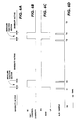
- FIG. 6A illustrates that diversity is effective, i.e., SW1 continually selects the strongest of the two receiver audio output signals, except when measurements are made during the relatively short sampling periods.
- the switch SW1 may connect either of the receivers to the audio processor 5 but during the relatively short measuring periods only receiver 1 is connected to element 5.
- Figure 6C indicates which antenna (6 or 8) is connected to the second receiver by way of switch ASW at any particular time. The particular antenna connected, of course, will depend upon the measured signal strength from the antennas which are sampled in the timed manner illustrated in Figure 6D.
- the right adjacent sector RA at time T2 would be determined to be larger than the left adjacent sector LA such that when diversity is reactivated, the active sector is changed from adjacent sector LA to adjacent RA. Additionally, in the period between T2 and T3, diversity is active between sector S and sector RA with LA "inactive". Moreover, as clearly illustrated in Figure 6A, at the end of time T3 a new measurement cycle begins but with sector RA measured during the active diversity period and sector LA measured when SW1 is forced to connect receiver 1 to processor 5.
- the exemplary embodiment of Figure 5 provides a circuit design that not only provides high quality communications but provides such results with a design well suited to a competitive commercial product. Moreover, the problems of the prior art are avoided by dynamically adapting to changing signal conditions whereby effective diversity is obtained to combat the effects of multipath fading as well as changing signal conditions due to movement of the mobile unit. The latter condition is measured for the purpose of using the strongest sector signal as well as determining when cell-to-cell transfer or handoff should occur.
- Figure 7 illustrates variations of the exemplary embodiment of Figure 5.
- the RSSI of sector S and receiver 1 may be measured and stored in logic 9, and the RSSI of additional sectors may also be measured during the periodic short samples of adjacent and other sectors, said other sectors being represented by sector B and antenna 12.
- the measuring of additional such signal strength samples may be used for storing average or rolling values or for comparison purposes with the RSSI of sector S along with other RSSI's for determining, among other things, the need for cell-to-cell transfer or handing off.
- the inclusion of other sectors in the diversity may take into consideration the RSSI of the sector diametrically opposite from the S sector in order to handle the case where the mobile unit is passing substantially directly under the antenna tower through the center of the cell.
- logic unit 9 may be advantageously designed to choose or base its decisions on more than one sample of RSSI from a particular sector. Such decisions may be based upon maintaining average readings of RSSI from each sector and updating the averages at each measurement cycle. The choice of which receiver to use when based upon such average signals is indicative of the position of the mobile unit and such averages would vary slowly.
- the sequence in which the switches are operated and the measurements taken may be varied within the teachings of our disclosure.
- the time during which diversity is active can be maximized by making the order in which the adjacent sectors are measured dependent upon which sector is currently active.
- the logic may be simplified by making the order fixed and extending the diversity inactive period to cover measurements of both adjacent sectors.
- contemporary circuit elements may be used to implement the exemplary embodiments illustrated and described.
- the switches such as SW1 could be implemented with commercially available solid state devices such as CMOS transmission gates.
- the antenna switch ASW could also be a solid state device such as a pin diode RF switch.
- the logic element 9 could be easily implemented by way of programming conventional microprocessors.
Landscapes
- Engineering & Computer Science (AREA)
- Computer Networks & Wireless Communication (AREA)
- Signal Processing (AREA)
- Mobile Radio Communication Systems (AREA)
- Radio Transmission System (AREA)
Claims (17)
- Appareil pour l'obtention d'une diversité adaptative dans un système de télécommunications soumis à des conditions de trajets multiples, le dit appareil comprenant :une pluralité d'éléments de détection de signal directionnel (6, 7, 8), chaque dit élément pouvant normalement être mis en oeuvre pour détecter des signaux se propageant à partir d'un secteur respectif différent en un motif à plusieurs secteurs ;au moins deux récepteurs (1, 2), chaque récepteur étant relié à au moins un élément de ladite pluralité d'éléments de détection de signal (6, 7, 8) et produisant un signal de sortie indicatif de l'intensité du signal reçu ; etdes moyens logiques (4, 9) reliés auxdits récepteurs,caractérisé en ce queles dits moyens logiques (4, 9) peuvent être mis en oeuvre dans un premier mode pour déterminer en permanence quel signal de sortie de récepteur est indicatif du signal reçu le plus intense en provenance d'un abonné particulier et pour relier seulement le dit signal reçu le plus intense à utiliser dans le dit système de télécommunications ; eten ce que les dits moyens logiques (4, 9) peuvent être mis en oeuvre dans un second mode périodique pour relier un récepteur particulier des dits récepteurs (1) pour entrer seulement son signal reçu dans le dit système de télécommunications sans tenir compte du fait de savoir s'il reçoit le dit signal le plus intense en provenance du dit abonné particulier, les dits premier et second modes étant mutuellement exclusifs ;dans lequel le dit récepteur particulier des dits récepteurs (1) est relié à un seul élément de détection (7) et un autre des dits récepteurs (2) est relié, de façon à pouvoir être commuté, à l'un ou l'autre d'au moins deux autres éléments de détection (6, 8) de la dite pluralité ; etdans lequel les dits moyens logiques (4, 9) comprennent de plus des moyens pouvant être mis en oeuvre dans le dit second mode pour mesurer les signaux des dits au moins deux autres éléments de détection et pour relier le plus intense des dits signaux, en provenance du dit substrat particulier, au dit autre des dits récepteurs (2).
- Appareil selon la revendication 1, dans lequel les dits moyens logiques comprennent un comparateur pour déterminer en permanence, dans le dit premier mode, quel signal de sortie de récepteur est indicatif du signal reçu le plus intense.
- Appareil selon la revendication 1 ou 2, dans lequel les dits éléments de détection sont des moyens formant antenne directionnelle et les dits au moins deux éléments de détection détectent des signaux se propageant à partir de secteurs adjacents au secteur dans lequel le dit élément de détection unique peut être mis en oeuvre.
- Appareil selon la revendication 3, dans lequel le dit système de télécommunications est un système de téléphonie mobile cellulaire qui comprend un processeur de signal et dans lequel les signaux reliés à ce dernier, en provenance des récepteurs, sont des signaux audio.
- Appareil selon la revendication 4, dans lequel les moyens logiques comprennent des moyens formant convertisseur analogique-numérique et dans lequel les dits moyens logiques mesurent l'intensité du signal reçu du dit récepteur particulier des dits récepteurs quand ils sont dans le dit premier mode.
- Appareil selon la revendication 5, dans lequel les valeurs de l'intensité du signal reçu, mesurées par les dits moyens logiques, quand ils sont dans les dits premier et second modes, sont utilisées pour déterminer à quel moment il est nécessaire de transférer les communications vers une autre cellule.
- Appareil selon la revendication 6, dans lequel les premier et second modes de mise en oeuvre se produisent pour des périodes de temps prédéterminées et dans lequel la période de temps pour le dit premier mode est sensiblement plus longue que celle du dit second mode.
- Appareil de diversité adaptative à utiliser avec un élément de traitement de signal (5) d'un système de téléphonie cellulaire, le dit appareil comprenant :une pluralité d'antennes directionnelles (6, 7, 8), chaque antenne pouvant être mise en oeuvre pour détecter des signaux se propageant principalement à partir d'un secteur différent respectif (S, LA, RA) d'une cellule à plusieurs secteurs ;une pluralité de groupes de récepteurs, chaque groupe comprenant au moins deux récepteurs (1, 2), chacun recevant des signaux en provenance d'au moins l'une des dites antennes ; etdes moyens formant un comparateur de signal (4) reliés à chacun des dits groupes pour déterminer celui des dits au moins deux récepteurs qui produit le signal de sortie le plus intense,caractérisé en ce que l'appareil comprend de plus :un élément de commutation (SW1) dans chacun des dits groupes, pouvant être mis en oeuvre dans un premier mode et sensible au dit comparateur pour relier le récepteur ayant le signal de sortie le plus intense au dit élément de traitement de signal ;des moyens de traitement logique (9) pour obliger, de façon périodique, le dit élément de commutation à fonctionner dans un second mode pour relier un signal particulier des dits signaux de sortie de récepteur (1) d'un groupe au dit élément de traitement de signal (5) pendant une période de temps prédéterminée, que le signal de sortie du dit récepteur particulier soit ou non le plus intense des dits signaux de sortie, et en ce que,pendant la connexion périodique du dit récepteur particulier à l'élément de traitement de signal, les dits moyens de traitement logique mesurent l'intensité du signal reçu en provenance du dit abonné particulier pour chaque antenne reliée à un autre récepteur de chaque groupe et relient ensuite l'antenne, ayant l'intensité la plus grande du signal en provenance du dit abonné particulier, au dit autre récepteur pour le premier mode de fonctionnement suivant.
- Appareil selon la revendication 8, dans lequel le premier mode se produit pendant une période de temps prédéterminée et dans lequel la période de temps pour le dit second mode est sensiblement plus courte que celle du dit premier mode.
- Appareil selon la revendication 8, dans lequel l'antenne reliée au dit récepteur particulier d'un groupe sert pour un secteur particulier et les antennes reliées au dit autre récepteur servent pour des secteurs adjacents.
- Appareil selon la revendication 8, dans lequel les moyens de traitement logique mesurent l'intensité du signal reçu du dit récepteur particulier des dits récepteurs quand ils sont dans le premier mode.
- Appareil selon la revendication 11, dans lequel les valeurs de l'intensité du signal reçu, mesurées par les dits moyens de traitement logique quand ils sont dans les premier et second modes, sont utilisées pour déterminer à quel moment il est nécessaire de transférer les communications vers une autre cellule.
- Procédé d'obtention d'une diversité adaptative dans un système de télécommunications soumis à des conditions de trajets multiples, le dit procédé comprenant :l'agencement de plusieurs détecteurs de signal (6, 7, 8) pour détecter des signaux se propageant à partir d'un motif à plusieurs secteurs où chaque détecteur peut normalement être mis en oeuvre pour détecter des signaux provenant d'un secteur différent respectif du motif ;la connexion d'un premier récepteur de signal (1) à l'un des dits détecteurs (7) ;la connexion d'un second récepteur de signal (2) pour recevoir des signaux en provenance d'un détecteur d'une pluralité d'autres détecteurs des dits détecteurs (6, 8) ;la comparaison, dans un premier mode de fonctionnement, de l'intensité du signal reçu du dit premier récepteur (1) à l'intensité du signal reçu du dit second récepteur (2) et la connexion du signal, en provenance du récepteur ayant l'intensité du signal reçu la plus forte, en provenance d'un abonné particulier, au dit système de télécommunications ;la comparaison, dans un second mode périodique de fonctionnement, de l'intensité du signal reçu en provenance de chacun des dits autres détecteurs des dits détecteurs (6, 8) de sorte que le détecteur, parmi les dits autres détecteurs, procurant le signal le plus intense en provenance du dit abonné particulier, est relié au dit second récepteur (2) ; etla connexion du signal en provenance du dit premier récepteur (1) au dit système de télécommunications quand il est dans le dit second mode sans tenir compte du fait de savoir s'il est en train de recevoir le signal le plus intense en provenance du dit abonné particulier.
- Procédé selon la revendication 13, dans lequel les dits autres détecteurs des dits détecteurs sont agencés pour détecter des signaux en provenance de secteurs adjacents aux secteurs contenant les dits détecteurs particuliers des dits détecteurs.
- Procédé selon la revendication 13 ou 14, comprenant de plus les étapes suivantes :la mesure des intensités du signal reçu des dits premiers détecteurs dans le dit premier mode ;la mesure des intensités du signal reçu des dits autres détecteurs des dits détecteurs dans le dit second mode ; etl'utilisation desdites intensités mesurées du signal pour déterminer à quel moment il est nécessaire de transférer les communications vers un autre motif à plusieurs secteurs.
- Procédé selon la revendication 13, 14 ou 15, comprenant de plus l'étape suivante :
la commande des premier et second modes devant respectivement se produire de manière périodique pendant des première et seconde périodes de temps, et dans lequel la dite seconde période de temps est sensiblement plus courte que la dite première période de temps. - Procédé selon la revendication 13, 14, 15 ou 16, dans lequel le système de télécommunications est un système de téléphonie mobile cellulaire et dans lequel les dits détecteurs sont des antennes directionnelles pour produire des signaux audio au niveau des sorties des dits récepteurs.
Applications Claiming Priority (2)
| Application Number | Priority Date | Filing Date | Title |
|---|---|---|---|
| US511348 | 1990-04-19 | ||
| US07/511,348 US5119501A (en) | 1990-04-19 | 1990-04-19 | Adaptive diversity equipment arrangement for cellular mobile telephone systems |
Publications (3)
| Publication Number | Publication Date |
|---|---|
| EP0454368A2 EP0454368A2 (fr) | 1991-10-30 |
| EP0454368A3 EP0454368A3 (en) | 1992-12-02 |
| EP0454368B1 true EP0454368B1 (fr) | 1997-05-28 |
Family
ID=24034509
Family Applications (1)
| Application Number | Title | Priority Date | Filing Date |
|---|---|---|---|
| EP91303508A Expired - Lifetime EP0454368B1 (fr) | 1990-04-19 | 1991-04-19 | Installation de diversité adaptative pour systèmes téléphoniques mobiles cellulaires |
Country Status (8)
| Country | Link |
|---|---|
| US (1) | US5119501A (fr) |
| EP (1) | EP0454368B1 (fr) |
| JP (1) | JP2708137B2 (fr) |
| CA (2) | CA2034401C (fr) |
| DE (1) | DE69126235T2 (fr) |
| DK (1) | DK0454368T3 (fr) |
| ES (1) | ES2100932T3 (fr) |
| HK (1) | HK1007847A1 (fr) |
Families Citing this family (26)
| Publication number | Priority date | Publication date | Assignee | Title |
|---|---|---|---|---|
| JP2552928B2 (ja) * | 1990-01-31 | 1996-11-13 | 三菱電機株式会社 | アンテナ選択ダイバーシチ受信装置 |
| FI91344C (fi) * | 1991-03-05 | 1994-06-10 | Nokia Telecommunications Oy | Solukkoradioverkko, tukiasema sekä menetelmä liikennekapasiteetin säätämiseksi alueellisesti solukkoradioverkossa |
| JP2949533B2 (ja) * | 1991-09-03 | 1999-09-13 | 日本電信電話株式会社 | 移動通信無線ゾーン構成方法 |
| GB2271246B (en) * | 1992-10-03 | 1997-02-12 | Motorola Ltd | Sectorized cellular radio base station antenna |
| GB2281479B (en) * | 1993-08-27 | 1997-09-03 | Nokia Telecommunications Oy | Radio receiving apparatus |
| FI934052A7 (fi) * | 1993-09-15 | 1995-03-16 | Nokia Telecommunications Oy | Menetelmä radiovastaanotinyksikön toiminnan valvomiseksi sekä vastaanotinyksikkö |
| DK0987851T3 (da) * | 1993-09-30 | 2003-09-08 | Conexant Systems Inc | Hjemmebase med flere antenner til digitale trådløse telefoner |
| US5481571A (en) * | 1993-11-12 | 1996-01-02 | Pacific Communication Sciences, Inc. | Method and apparatus for switching between radio frequency circuits |
| US5740526A (en) * | 1994-06-01 | 1998-04-14 | Bonta; Jeffrey D. | Method and apparatus for selecting two antennas from which to receive a communication signal |
| US5640695A (en) * | 1994-06-14 | 1997-06-17 | Electrocom Communication Systems L.P. | Multibranched selectively combined diversity controller |
| US5737689A (en) * | 1994-06-14 | 1998-04-07 | Telefonaktiebolaget Lm Ericsson | Method for preventing calls of bad quality from being disconnected in a cellular mobile radio system |
| US5586170A (en) * | 1994-08-19 | 1996-12-17 | Georgia Tech Research Corporation | Cellular devices, systems and methods using intercell macro-diversity and dynamic channel allocation |
| US5649306A (en) * | 1994-09-16 | 1997-07-15 | Motorola, Inc. | Portable radio housing incorporating diversity antenna structure |
| GB2294609B (en) * | 1994-10-26 | 1999-01-27 | Northern Telecom Ltd | A base station arrangement |
| FI956060A7 (fi) * | 1995-12-15 | 1997-06-16 | Nokia Corp | Sektoroitu tukiasema |
| FI107485B (fi) * | 1996-04-17 | 2001-08-15 | Nokia Mobile Phones Ltd | Diversiteettimenetelmä, radiovastaanotin ja radiojärjestelmä |
| JP3076252B2 (ja) * | 1996-11-25 | 2000-08-14 | 日本電気株式会社 | セルラー移動通信システムにおける多セクター切替制御装置 |
| US5991282A (en) * | 1997-05-28 | 1999-11-23 | Telefonaktiebolaget Lm Ericsson | Radio communication system with diversity reception on a time-slot by time-slot basis |
| SE9702370L (sv) | 1997-06-19 | 1998-12-20 | Ericsson Telefon Ab L M | Balanserad diversitet |
| US5991643A (en) * | 1997-11-28 | 1999-11-23 | Acer Peripherals, Inc. | Radio transceiver having switchable antennas |
| DE19825536B4 (de) | 1998-06-08 | 2005-05-19 | IQ wireless GmbH, Entwicklungsgesellschaft für Systeme und Technologien der Telekommunikation | Verfahren und Vorrichtung für ein vollduplexfähiges Funkübertragungssystem mit CDMA-Zugriff |
| DE19906867C1 (de) * | 1999-02-18 | 2000-07-06 | Weidmueller Interface | Verfahren und Vorrichtung zur seriellen Datenübertragung |
| US7024168B1 (en) | 1999-07-07 | 2006-04-04 | Telefonaktiebolaget L M Ericsson (Publ) | Controlled antenna diversity |
| US7123876B2 (en) * | 2001-11-01 | 2006-10-17 | Motia | Easy set-up, vehicle mounted, in-motion tracking, satellite antenna |
| US6862434B2 (en) * | 2002-07-26 | 2005-03-01 | Qualcomm Inc. | Transmission diversity systems |
| DE10311836B4 (de) * | 2003-03-18 | 2006-10-05 | Integrated Electronic Systems !Sys Consulting Gmbh | Ferngesteuertes Industriegerät |
Citations (1)
| Publication number | Priority date | Publication date | Assignee | Title |
|---|---|---|---|---|
| US4694484A (en) * | 1986-02-18 | 1987-09-15 | Motorola, Inc. | Cellular radiotelephone land station |
Family Cites Families (7)
| Publication number | Priority date | Publication date | Assignee | Title |
|---|---|---|---|---|
| JPS60223336A (ja) * | 1984-04-20 | 1985-11-07 | Matsushita Electric Ind Co Ltd | 角度ダイバ−シテイ受信装置 |
| JPS6163120A (ja) * | 1984-09-05 | 1986-04-01 | Matsushita Electric Ind Co Ltd | 基地局受信装置 |
| US4823398A (en) * | 1985-12-23 | 1989-04-18 | Kazuya Hashimoto | Diversity receiver |
| US4704734A (en) * | 1986-02-18 | 1987-11-03 | Motorola, Inc. | Method and apparatus for signal strength measurement and antenna selection in cellular radiotelephone systems |
| US4726050A (en) * | 1986-02-18 | 1988-02-16 | Motorola, Inc. | Scanning receiver allocation method and apparatus for cellular radiotelephone systems |
| US4797947A (en) * | 1987-05-01 | 1989-01-10 | Motorola, Inc. | Microcellular communications system using macrodiversity |
| US4881082A (en) * | 1988-03-03 | 1989-11-14 | Motorola, Inc. | Antenna beam boundary detector for preliminary handoff determination |
-
1990
- 1990-04-19 US US07/511,348 patent/US5119501A/en not_active Expired - Lifetime
-
1991
- 1991-01-17 CA CA002034401A patent/CA2034401C/fr not_active Expired - Fee Related
- 1991-04-08 CA CA002040061A patent/CA2040061A1/fr not_active Abandoned
- 1991-04-19 ES ES91303508T patent/ES2100932T3/es not_active Expired - Lifetime
- 1991-04-19 EP EP91303508A patent/EP0454368B1/fr not_active Expired - Lifetime
- 1991-04-19 DK DK91303508.5T patent/DK0454368T3/da active
- 1991-04-19 JP JP3088408A patent/JP2708137B2/ja not_active Expired - Lifetime
- 1991-04-19 DE DE69126235T patent/DE69126235T2/de not_active Expired - Fee Related
-
1998
- 1998-06-26 HK HK98107053A patent/HK1007847A1/en not_active IP Right Cessation
Patent Citations (1)
| Publication number | Priority date | Publication date | Assignee | Title |
|---|---|---|---|---|
| US4694484A (en) * | 1986-02-18 | 1987-09-15 | Motorola, Inc. | Cellular radiotelephone land station |
Also Published As
| Publication number | Publication date |
|---|---|
| US5119501A (en) | 1992-06-02 |
| DE69126235T2 (de) | 1998-01-08 |
| CA2034401C (fr) | 1999-11-16 |
| DE69126235D1 (de) | 1997-07-03 |
| EP0454368A3 (en) | 1992-12-02 |
| EP0454368A2 (fr) | 1991-10-30 |
| JPH066276A (ja) | 1994-01-14 |
| DK0454368T3 (da) | 1997-06-30 |
| ES2100932T3 (es) | 1997-07-01 |
| CA2040061A1 (fr) | 1991-10-20 |
| CA2034401A1 (fr) | 1991-10-20 |
| JP2708137B2 (ja) | 1998-02-04 |
| HK1007847A1 (en) | 1999-04-23 |
Similar Documents
| Publication | Publication Date | Title |
|---|---|---|
| EP0454368B1 (fr) | Installation de diversité adaptative pour systèmes téléphoniques mobiles cellulaires | |
| HK1007847B (en) | Adaptive diversity equipment arrangement for cellular mobile telephone systems | |
| KR100213691B1 (ko) | 통신 신호를 수신하기 위한 2개의 안테나를 선택하는 방법 및 장치 | |
| US4751725A (en) | VOX remote unit control in a cellular system | |
| US6438389B1 (en) | Wireless communication system with adaptive beam selection | |
| US4654879A (en) | Cellular mobile radio subscriber location detection | |
| EP1078276B1 (fr) | Methode permettant de determiner la direction d'arrivee d'un signal et appareil correspondant | |
| KR20010062759A (ko) | 지능 안테나를 위한 동적 채널 할당 방법 | |
| US7286800B2 (en) | Multi-beam antenna reception device and multi-beam reception method | |
| KR100547805B1 (ko) | 소프터 핸드오프를 지원하는 이동 통신 시스템에서의 역방향 링크 결합 장치 및 방법 | |
| JPS6355824B2 (fr) | ||
| CA1209210A (fr) | Methode et appareil pour mesurer l'intensite d'un signal radiofrequence | |
| KR100488079B1 (ko) | 이동통신 시스템의 핸드오프 방법 | |
| JP4024966B2 (ja) | アダプティブアレイ基地局 | |
| JPH07101950B2 (ja) | 移動セルラ通信システムおよび音声チャネル干渉を減少させる方法 | |
| WO2002015412A2 (fr) | Mesure de signaux dans des systemes de radiocommunications | |
| JP3862260B2 (ja) | 移動局 | |
| HK1004592B (en) | Vox remote unit control in a cellular system | |
| JPH02303236A (ja) | 自動車電話方式 |
Legal Events
| Date | Code | Title | Description |
|---|---|---|---|
| PUAI | Public reference made under article 153(3) epc to a published international application that has entered the european phase |
Free format text: ORIGINAL CODE: 0009012 |
|
| AK | Designated contracting states |
Kind code of ref document: A2 Designated state(s): BE DE DK ES FR GB IT SE |
|
| PUAL | Search report despatched |
Free format text: ORIGINAL CODE: 0009013 |
|
| AK | Designated contracting states |
Kind code of ref document: A3 Designated state(s): BE DE DK ES FR GB IT SE |
|
| 17P | Request for examination filed |
Effective date: 19930526 |
|
| 17Q | First examination report despatched |
Effective date: 19950801 |
|
| GRAG | Despatch of communication of intention to grant |
Free format text: ORIGINAL CODE: EPIDOS AGRA |
|
| GRAH | Despatch of communication of intention to grant a patent |
Free format text: ORIGINAL CODE: EPIDOS IGRA |
|
| GRAH | Despatch of communication of intention to grant a patent |
Free format text: ORIGINAL CODE: EPIDOS IGRA |
|
| GRAA | (expected) grant |
Free format text: ORIGINAL CODE: 0009210 |
|
| AK | Designated contracting states |
Kind code of ref document: B1 Designated state(s): BE DE DK ES FR GB IT SE |
|
| REG | Reference to a national code |
Ref country code: DK Ref legal event code: T3 |
|
| REG | Reference to a national code |
Ref country code: ES Ref legal event code: FG2A Ref document number: 2100932 Country of ref document: ES Kind code of ref document: T3 |
|
| REF | Corresponds to: |
Ref document number: 69126235 Country of ref document: DE Date of ref document: 19970703 |
|
| ET | Fr: translation filed | ||
| PLBE | No opposition filed within time limit |
Free format text: ORIGINAL CODE: 0009261 |
|
| STAA | Information on the status of an ep patent application or granted ep patent |
Free format text: STATUS: NO OPPOSITION FILED WITHIN TIME LIMIT |
|
| 26N | No opposition filed | ||
| PGFP | Annual fee paid to national office [announced via postgrant information from national office to epo] |
Ref country code: FR Payment date: 20000330 Year of fee payment: 10 |
|
| PGFP | Annual fee paid to national office [announced via postgrant information from national office to epo] |
Ref country code: SE Payment date: 20000331 Year of fee payment: 10 Ref country code: DE Payment date: 20000331 Year of fee payment: 10 |
|
| PGFP | Annual fee paid to national office [announced via postgrant information from national office to epo] |
Ref country code: GB Payment date: 20000403 Year of fee payment: 10 Ref country code: DK Payment date: 20000403 Year of fee payment: 10 |
|
| PGFP | Annual fee paid to national office [announced via postgrant information from national office to epo] |
Ref country code: BE Payment date: 20000421 Year of fee payment: 10 |
|
| PGFP | Annual fee paid to national office [announced via postgrant information from national office to epo] |
Ref country code: ES Payment date: 20000510 Year of fee payment: 10 |
|
| PG25 | Lapsed in a contracting state [announced via postgrant information from national office to epo] |
Ref country code: GB Free format text: LAPSE BECAUSE OF NON-PAYMENT OF DUE FEES Effective date: 20010419 Ref country code: DK Free format text: LAPSE BECAUSE OF NON-PAYMENT OF DUE FEES Effective date: 20010419 |
|
| PG25 | Lapsed in a contracting state [announced via postgrant information from national office to epo] |
Ref country code: SE Free format text: LAPSE BECAUSE OF NON-PAYMENT OF DUE FEES Effective date: 20010420 Ref country code: ES Free format text: LAPSE BECAUSE OF NON-PAYMENT OF DUE FEES Effective date: 20010420 |
|
| PG25 | Lapsed in a contracting state [announced via postgrant information from national office to epo] |
Ref country code: FR Free format text: THE PATENT HAS BEEN ANNULLED BY A DECISION OF A NATIONAL AUTHORITY Effective date: 20010430 Ref country code: BE Free format text: LAPSE BECAUSE OF NON-PAYMENT OF DUE FEES Effective date: 20010430 |
|
| BERE | Be: lapsed |
Owner name: ERICSSON GE MOBILE COMMUNICATIONS INC. Effective date: 20010430 |
|
| EUG | Se: european patent has lapsed |
Ref document number: 91303508.5 |
|
| GBPC | Gb: european patent ceased through non-payment of renewal fee |
Effective date: 20010419 |
|
| PG25 | Lapsed in a contracting state [announced via postgrant information from national office to epo] |
Ref country code: DE Free format text: LAPSE BECAUSE OF NON-PAYMENT OF DUE FEES Effective date: 20020201 |
|
| REG | Reference to a national code |
Ref country code: FR Ref legal event code: ST |
|
| REG | Reference to a national code |
Ref country code: ES Ref legal event code: FD2A Effective date: 20030303 |
|
| PG25 | Lapsed in a contracting state [announced via postgrant information from national office to epo] |
Ref country code: IT Free format text: LAPSE BECAUSE OF NON-PAYMENT OF DUE FEES Effective date: 20050419 |