EP0454403A1 - Schaberklinge mit integrierten Befestigungsmitteln und Verfahren zu seiner Herstellung - Google Patents
Schaberklinge mit integrierten Befestigungsmitteln und Verfahren zu seiner Herstellung Download PDFInfo
- Publication number
- EP0454403A1 EP0454403A1 EP91303608A EP91303608A EP0454403A1 EP 0454403 A1 EP0454403 A1 EP 0454403A1 EP 91303608 A EP91303608 A EP 91303608A EP 91303608 A EP91303608 A EP 91303608A EP 0454403 A1 EP0454403 A1 EP 0454403A1
- Authority
- EP
- European Patent Office
- Prior art keywords
- blade
- strip
- recess means
- holder
- doctor blade
- Prior art date
- Legal status (The legal status is an assumption and is not a legal conclusion. Google has not performed a legal analysis and makes no representation as to the accuracy of the status listed.)
- Withdrawn
Links
- 238000004519 manufacturing process Methods 0.000 title claims description 9
- 239000004033 plastic Substances 0.000 claims abstract description 9
- 229920003023 plastic Polymers 0.000 claims abstract description 9
- 239000002131 composite material Substances 0.000 claims abstract description 4
- 238000007493 shaping process Methods 0.000 claims description 4
- 238000009434 installation Methods 0.000 claims description 3
- 230000000717 retained effect Effects 0.000 claims description 2
- 239000000463 material Substances 0.000 abstract description 10
- 238000000034 method Methods 0.000 description 7
- 239000000356 contaminant Substances 0.000 description 3
- 239000002650 laminated plastic Substances 0.000 description 3
- 238000009740 moulding (composite fabrication) Methods 0.000 description 3
- 230000000694 effects Effects 0.000 description 2
- 239000000835 fiber Substances 0.000 description 2
- 238000003754 machining Methods 0.000 description 2
- 239000002184 metal Substances 0.000 description 2
- 229910000906 Bronze Inorganic materials 0.000 description 1
- 229920002430 Fibre-reinforced plastic Polymers 0.000 description 1
- 239000004698 Polyethylene Substances 0.000 description 1
- 238000005452 bending Methods 0.000 description 1
- 239000010974 bronze Substances 0.000 description 1
- 238000003490 calendering Methods 0.000 description 1
- KUNSUQLRTQLHQQ-UHFFFAOYSA-N copper tin Chemical compound [Cu].[Sn] KUNSUQLRTQLHQQ-UHFFFAOYSA-N 0.000 description 1
- 238000005520 cutting process Methods 0.000 description 1
- 238000001035 drying Methods 0.000 description 1
- 239000011151 fibre-reinforced plastic Substances 0.000 description 1
- 239000011152 fibreglass Substances 0.000 description 1
- 239000005340 laminated glass Substances 0.000 description 1
- 229910001092 metal group alloy Inorganic materials 0.000 description 1
- -1 polyethylene Polymers 0.000 description 1
- 229920000573 polyethylene Polymers 0.000 description 1
- 238000003825 pressing Methods 0.000 description 1
- 238000004080 punching Methods 0.000 description 1
- 230000000284 resting effect Effects 0.000 description 1
- 239000010935 stainless steel Substances 0.000 description 1
- 229910001220 stainless steel Inorganic materials 0.000 description 1
- 229920002994 synthetic fiber Polymers 0.000 description 1
- 229920001567 vinyl ester resin Polymers 0.000 description 1
Images


Classifications
-
- D—TEXTILES; PAPER
- D21—PAPER-MAKING; PRODUCTION OF CELLULOSE
- D21G—CALENDERS; ACCESSORIES FOR PAPER-MAKING MACHINES
- D21G3/00—Doctors
- D21G3/005—Doctor knifes
Definitions
- This invention pertains to a blade used as a doctor for a pulp or papermaking machine, and more particularly to a blade with integral mounting means for mounting it on a blade holder.
- Pulp or papermaking machines utilize machine rolls. Such machine rolls are used during various aspects of the process, for example, in the forming, pressing, drying or calendering sections.
- the operation of machine rolls requires a device to remove contaminants which form on the roll surface and/or to peel off a sheet or web from the rolls.
- a traditional method of achieving this is through the use of a mechanical device commonly referred to as a doctor or doctor blade.
- the failure to remove the contaminants or the sheet effectively can have a catastrophic effect on the quality of the product being produced.
- the doctor blade is typically fastened by a doctor blade holder to a structural beam which is adjustably supported across the papermaking machine on which the blade holder and replaceable blade is provided.
- the doctor blade comes in direct contact with the roll surface so as to scrape off any contaminants from the roll surface, or to scrape off the whole pulp or paper web sheet, or parts thereof.
- Laminated plastic doctor blades and blade holders such as type KF-35, KF-35A or PNEUFLEX blade holder are manufactured by Albany International Corp..
- the blade should be securely attached to the blade holder as a doctor without a blade will not scrape anything from the roll, and as aforesaid, this will have a catastrophic effect on the machine production. But even worse, the blade or a part thereof can come off and fall in the machine and may irreparably damage the pulp or paper machine clothing; the roll may also be damaged because of direct and sudden contact with the blade holder.
- the ultimate solution to prevent the aforesaid catastrophic situation would be to permanently fasten the blade to the holder or to make it as an integral part of the holder. But, doctor blades do wear with time. Depending on the application, they can last anywhere from a few hours to several months. Therefore, a doctor blade must be a replaceable item.
- the blade and holder design should allow for easy, fast and safe blade replacement so as to ensure that neither the blade, nor a part thereof, like the fastening devices for example, will come off and fall into the machine.
- a common design in the industry is to put along one edge of the blade some types of rivets, or some other mechanical retainers that could be, for example, rivetted, glued, or press-fitted to the blade.
- the holder is then manufactured with a slot incorporating a step or a groove.
- the edge of the blade with the retainers can be slid into the groove though one end of the holder.
- One such doctor blade and a common holder are disclosed in Canadian Patent no. 803,198.
- Alternative designs are also available which allow a blade to be removed from the front of the holder, for the few applications where the access through the ends is limited.
- Another design used in the industry consists of making the blade with built-in retainers whereby there is no mechanically fastened part on the blade that can come off.
- One know way to do this is to machine the blade out of thicker material, leaving a narrow step along one edge that will retain the blade in the holder slot.
- This method is widely used to manufacture polyethylene doctor blades, where machining is fast and easy, and where thicker material is also required to add strength or to increase wear life. Theoretically, this method can be used to manufacture blades out of other popular materials, like metal or laminated plastics.
- the present invention provides a doctor blade for installation in a doctoring blade holder in a papermaking machine, said holder comprising two opposed jaws, said doctoring blade comprising an elongate strip defined by a first longitudinal and a second longitudinal side, said first longitudinal side having a doctoring surface, first recess means formed integrally from said strip and extending in a first direction away from said strip, and, second recess means formed integrally from said strip and extending in a second direction opposite said first direction, said first and second recess means being arranged and constructed to maintain said blade within said holder by contacting said first and second jaws respectively.
- said first and second recess means have respective regions maintained in a spaced relation from said strip by the plastic deformation thereof.
- the strip may have first and second surfaces and the first recess means may extend above said first surface and said second recess may extend below said second surface.
- the second recess means is flexible to apply a biasing force on said blade when said blade is inserted in said holder.
- the first and/or second recess means may be formed by arcuate cuts in the strip.
- the first recess means may be defined by arcuate cuts extending away from said second side, and the second recess means may be defined by arcuate cuts extending toward said second side.
- the first recess means may comprise longitudinal straps cut from the strip, and may be formed by pairs of cuts parallel to said second side.
- the second recess means may be defined by transversal cuts in said strip, which cuts preferably extend from the second side of the strip.
- the doctoring blade may be made of a metallic or plastics composite material.
- the present invention further provides a doctor blade assembly for doctoring a roll in a papermaking machine comprising a blade holder having first and second jaws defining a cavity therebetween and a blade, as specified above, capable of being retained in the cavity.
- the assembly may comprise a blade holder having first and second longitudinal jaws defining a cavity therebetween, and, a blade adapted to be disposed in said cavity, said blade including an elongate strip having a first side with a doctoring surface disposed away from said blade holder, and a second side disposed in said cavity, first recess means formed integrally from said strip, said first recess means co-operating with said first longitudinal jaw to retain said blade, and, second recess means formed from said strip and arranged and constructed to bias said strip away from said second longitudinal jaw.
- the present invention also provides a method of making a doctor blade, as specified above, which method comprises forming an elongate strip with a first side having a doctoring surface, and a second side opposite said first side, and, forming first and second recess means integrally from the strip, preferably by plastically deforming said strip, and optionally, shaping said first recess means to retain said blade in a holder, and shaping said second recess means to bias said blade against said holder.
- a blade may be made by taking an elongate strip of suitable blade material and punching two sets of recess means adjacent to a longitudinal side of the material, one set of recesses being deformed to form retainers and the second set of recesses being deformed to form the biasing means.
- the doctor blade 10 shown in Figures 1-4 consists of a strip 12 made of a metal, a metal alloy or a fiber reinforced laminated plastics material such as a plastics laminated base of, for example, a vinyl ester reinforced by fiberglass fibers.
- strip 12 is about 0.060 ⁇ (1.5 mm) thick, and 3 ⁇ (78 mm) wide.
- One side 14 of strip 12 may be bevelled at an angle of about 45° to form a doctoring surface 16.
- tabs 20, 22 are formed by making semi-circular cuts 26, 28 in the strip 12. As clearly shown in Figure 1 the tabs 20, 22 are cut symmetrically along axes normal to the longitudinal axis of blade 12. Moreover, tabs 20 and tabs 22 are cut so they are facing in opposite directions.
- the tabs 20, 22 are pushed out laterally with respect to the strip 12.
- tabs 20 are bent toward one side of the strip 12 while tabs 22 are bent toward the other side.
- the size of the cuts 26, 28 and their distance from side 18 are selected to ensure that the tabs are formed by plastically deforming the strip 12 (i.e. the tabs remain in the bent position after the bending force is removed).
- tab 20 is shaped so that, as shown in Figure 3, it first moves outwardly away from strip 12 but just before its tip, the tab curves back toward the blade to define an arc.
- tab 20 is also curved in the longitudinal direction to reinforce the tab structurally.
- tab 20 is formed with a contact zone or point 30 which is the furthest point on tab 20 from strip 12.
- tab 22 is curved in two dimensions to form a contact zone or point 32.
- a typical doctor blade holder 34 consists of two jaws 36, 38 joined by nut-and-bolt arrangements 40.
- Jaw 38 may be a single longitudinal unit, or may consist of a plurality of parallel fingers.
- Jaw 36 has a longitudinal channel 40 defined between a lip 42 and a wall 44.
- Jaw 38 is also formed with a channel 46 defined at one end by a step 48.
- strip 12 After strip 12 is formed as described above and in Figures 1-3, it may be inserted into the holder by sliding it into the cavity formed by channels 40, 46. A sharp tool may be used to engage hole 24 to pull the blade into the holder.
- the holder 34 and blade 12 are dimensioned so that once the blade is seated in its place it is maintained there by interference fit with the holder. More particularly, tabs 20 are seated so that the contact point 30 is resting on the web 50 of jaw 36 with the tip of the tab 20 being in contact with lip 42. Tab 22 rests against jaw 38 and it is flexible to bias the blade.
- the doctoring surface 16 rests on a roller 52 in the usual manner.
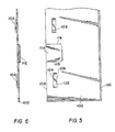
- strip 100 is made with a set of straps 102, formed by making two longitudinal cuts 104, 106.
- the opposite edge 110 is slanted to form a doctoring surface.
- blade 100 is also provided with transversal tabs 112.
- Tabs 112 are formed by making two transversal cuts 116, 118 extending from edge 108 inwardly.
- Tabs 112 are bent away from blade 100 in a direction opposite from straps 102 as shown in Figure 6.
- Straps 102 and tabs 112 are dimensioned so that when blade 100 is inserted into holder 34 ( Figure 7), straps 102 are in contact with or at least adjacent to lip 42 to retain the blade within the holder. Tabs 112 bear against step 48 to bias the blade within the holder.
- Blades 10, 100 may be made of a metallic or plastics material which is resilient enough so that the integral tabs 20, 22, 112 or strap 102 cut therefrom maintain some degree of springiness sufficient to keep the blade within the holder.
- the tabs and/or straps which form the recesses used to retain the blade within the holder each have a zone or region disposed on one side or another of the blade. These zones are maintained in their position by the plastic deformation of the blade used to generate the recesses.
Landscapes
- Paper (AREA)
Applications Claiming Priority (4)
| Application Number | Priority Date | Filing Date | Title |
|---|---|---|---|
| US512851 | 1990-04-23 | ||
| US07/512,851 US5110415A (en) | 1990-04-23 | 1990-04-23 | Composite doctor blade assembly for pulp or papermaking machine doctors |
| US63587690A | 1990-12-28 | 1990-12-28 | |
| US635876 | 2003-08-05 |
Publications (1)
| Publication Number | Publication Date |
|---|---|
| EP0454403A1 true EP0454403A1 (de) | 1991-10-30 |
Family
ID=27057684
Family Applications (1)
| Application Number | Title | Priority Date | Filing Date |
|---|---|---|---|
| EP91303608A Withdrawn EP0454403A1 (de) | 1990-04-23 | 1991-04-23 | Schaberklinge mit integrierten Befestigungsmitteln und Verfahren zu seiner Herstellung |
Country Status (1)
| Country | Link |
|---|---|
| EP (1) | EP0454403A1 (de) |
Cited By (1)
| Publication number | Priority date | Publication date | Assignee | Title |
|---|---|---|---|---|
| WO2007079502A2 (en) | 2006-01-06 | 2007-07-12 | Micrex Corporation | Microcreping traveling sheet material |
Citations (4)
| Publication number | Priority date | Publication date | Assignee | Title |
|---|---|---|---|---|
| DE561239C (de) * | 1930-07-31 | 1932-10-12 | Vickerys Ltd | Schaber fuer Papiermaschinen u. dgl. |
| GB800607A (en) * | 1956-01-13 | 1958-08-27 | Harold Eric Baliol Scott | Improvements in or relating to doctors for papermaking and other machines |
| US2972767A (en) * | 1956-01-27 | 1961-02-28 | Bird Machine Co | Doctor assembly and front removable blade and holder therefor with capacity for oscillation |
| DE1916725A1 (de) * | 1968-04-08 | 1969-10-30 | Lodding Engineering Corp | Vorrichtung zum Haltern und Einstellen eines Abstreichmessers oder Rakels |
-
1991
- 1991-04-23 EP EP91303608A patent/EP0454403A1/de not_active Withdrawn
Patent Citations (4)
| Publication number | Priority date | Publication date | Assignee | Title |
|---|---|---|---|---|
| DE561239C (de) * | 1930-07-31 | 1932-10-12 | Vickerys Ltd | Schaber fuer Papiermaschinen u. dgl. |
| GB800607A (en) * | 1956-01-13 | 1958-08-27 | Harold Eric Baliol Scott | Improvements in or relating to doctors for papermaking and other machines |
| US2972767A (en) * | 1956-01-27 | 1961-02-28 | Bird Machine Co | Doctor assembly and front removable blade and holder therefor with capacity for oscillation |
| DE1916725A1 (de) * | 1968-04-08 | 1969-10-30 | Lodding Engineering Corp | Vorrichtung zum Haltern und Einstellen eines Abstreichmessers oder Rakels |
Cited By (3)
| Publication number | Priority date | Publication date | Assignee | Title |
|---|---|---|---|---|
| WO2007079502A2 (en) | 2006-01-06 | 2007-07-12 | Micrex Corporation | Microcreping traveling sheet material |
| WO2007079502A3 (en) * | 2006-01-06 | 2007-11-15 | Micrex Corp | Microcreping traveling sheet material |
| US7854046B2 (en) | 2006-01-06 | 2010-12-21 | Micrex Corporation | Microcreping traveling sheet material |
Similar Documents
| Publication | Publication Date | Title |
|---|---|---|
| US5110415A (en) | Composite doctor blade assembly for pulp or papermaking machine doctors | |
| US6629475B1 (en) | Razor blade | |
| US4809421A (en) | Slotted shim | |
| US3835746A (en) | Die assembly and rule mounting means therefor | |
| EP0015580A1 (de) | Verfahren und/oder Vorrichtungen zum Stanzen von Löchern in Blech | |
| WO1999039884A8 (en) | Cutting apparatus and cutting method | |
| EP0418768A3 (en) | Stamping die, method of manufacture and tool for use in carrying out said process | |
| PL188020B1 (pl) | Matrycowy wycinak walcowy | |
| JPH10504494A (ja) | 切断定規及び段ボール切断方法 | |
| JP6948540B1 (ja) | ラベルカッターユニット、刃体、刃体の製造方法、刃体の製造装置 | |
| JPH0215360B2 (de) | ||
| CN100379631C (zh) | 冲压切割机覆盖物锁定装置 | |
| IT8223674A1 (it) | Disposizione di ceppo di freno | |
| EP0013628A1 (de) | Rollenlager | |
| KR20010013114A (ko) | 팽창된 메쉬 쉬트형성을 위하여 장치에서 슬릿 스트립의측면 엣지를 파지, 안내 및 운송하기 위한 장치 | |
| FI76009B (fi) | Rakelfaestanordning. | |
| JPH04240294A (ja) | 一体的装着手段付きドクターブレード及びその製造方法 | |
| US5740714A (en) | Rotary blade clamping assembly | |
| EP0406202A2 (de) | Klemmvorrichtung zur Herstellung von Nägeln | |
| EP0750535A4 (de) | Rasierklingenherstellung | |
| JPH0418061B2 (de) | ||
| GB2033803A (en) | Method of forming a cylindrical member | |
| GB2257084A (en) | Rotary-type sheet cutter | |
| EP1174536A3 (de) | Perforation einer Waschmaschinetrommel | |
| JPS60207799A (ja) | 紙せん断機 |
Legal Events
| Date | Code | Title | Description |
|---|---|---|---|
| PUAI | Public reference made under article 153(3) epc to a published international application that has entered the european phase |
Free format text: ORIGINAL CODE: 0009012 |
|
| AK | Designated contracting states |
Kind code of ref document: A1 Designated state(s): AT BE CH DE FR GB IT LI NL SE |
|
| 17P | Request for examination filed |
Effective date: 19911022 |
|
| STAA | Information on the status of an ep patent application or granted ep patent |
Free format text: STATUS: THE APPLICATION HAS BEEN WITHDRAWN |
|
| 18W | Application withdrawn |
Withdrawal date: 19911210 |