EP0454438A1 - Rotationsapparat, welcher in einem dynamischen Fluid gelagert ist - Google Patents
Rotationsapparat, welcher in einem dynamischen Fluid gelagert ist Download PDFInfo
- Publication number
- EP0454438A1 EP0454438A1 EP91303683A EP91303683A EP0454438A1 EP 0454438 A1 EP0454438 A1 EP 0454438A1 EP 91303683 A EP91303683 A EP 91303683A EP 91303683 A EP91303683 A EP 91303683A EP 0454438 A1 EP0454438 A1 EP 0454438A1
- Authority
- EP
- European Patent Office
- Prior art keywords
- shaft
- sleeve
- fixed member
- deflecting
- rotating
- Prior art date
- Legal status (The legal status is an assumption and is not a legal conclusion. Google has not performed a legal analysis and makes no representation as to the accuracy of the status listed.)
- Granted
Links
- 239000012530 fluid Substances 0.000 title claims abstract description 33
- 229920005989 resin Polymers 0.000 claims abstract description 17
- 239000011347 resin Substances 0.000 claims abstract description 17
- 239000000463 material Substances 0.000 claims abstract description 16
- 229920003002 synthetic resin Polymers 0.000 claims 2
- 239000000057 synthetic resin Substances 0.000 claims 2
- 230000002093 peripheral effect Effects 0.000 description 15
- 238000010276 construction Methods 0.000 description 13
- 239000000758 substrate Substances 0.000 description 6
- 230000000694 effects Effects 0.000 description 3
- 230000001050 lubricating effect Effects 0.000 description 3
- 238000004519 manufacturing process Methods 0.000 description 3
- 238000000465 moulding Methods 0.000 description 3
- 238000003384 imaging method Methods 0.000 description 2
- 238000010348 incorporation Methods 0.000 description 2
- 230000003287 optical effect Effects 0.000 description 2
- 230000008030 elimination Effects 0.000 description 1
- 238000003379 elimination reaction Methods 0.000 description 1
- 239000004519 grease Substances 0.000 description 1
- 239000007788 liquid Substances 0.000 description 1
- 238000005086 pumping Methods 0.000 description 1
Images


Classifications
-
- F—MECHANICAL ENGINEERING; LIGHTING; HEATING; WEAPONS; BLASTING
- F16—ENGINEERING ELEMENTS AND UNITS; GENERAL MEASURES FOR PRODUCING AND MAINTAINING EFFECTIVE FUNCTIONING OF MACHINES OR INSTALLATIONS; THERMAL INSULATION IN GENERAL
- F16C—SHAFTS; FLEXIBLE SHAFTS; ELEMENTS OR CRANKSHAFT MECHANISMS; ROTARY BODIES OTHER THAN GEARING ELEMENTS; BEARINGS
- F16C33/00—Parts of bearings; Special methods for making bearings or parts thereof
- F16C33/02—Parts of sliding-contact bearings
- F16C33/04—Brasses; Bushes; Linings
- F16C33/06—Sliding surface mainly made of metal
- F16C33/10—Construction relative to lubrication
- F16C33/1025—Construction relative to lubrication with liquid, e.g. oil, as lubricant
- F16C33/106—Details of distribution or circulation inside the bearings, e.g. details of the bearing surfaces to affect flow or pressure of the liquid
- F16C33/107—Grooves for generating pressure
-
- B—PERFORMING OPERATIONS; TRANSPORTING
- B41—PRINTING; LINING MACHINES; TYPEWRITERS; STAMPS
- B41J—TYPEWRITERS; SELECTIVE PRINTING MECHANISMS, i.e. MECHANISMS PRINTING OTHERWISE THAN FROM A FORME; CORRECTION OF TYPOGRAPHICAL ERRORS
- B41J2/00—Typewriters or selective printing mechanisms characterised by the printing or marking process for which they are designed
- B41J2/435—Typewriters or selective printing mechanisms characterised by the printing or marking process for which they are designed characterised by selective application of radiation to a printing material or impression-transfer material
- B41J2/47—Typewriters or selective printing mechanisms characterised by the printing or marking process for which they are designed characterised by selective application of radiation to a printing material or impression-transfer material using the combination of scanning and modulation of light
- B41J2/471—Typewriters or selective printing mechanisms characterised by the printing or marking process for which they are designed characterised by selective application of radiation to a printing material or impression-transfer material using the combination of scanning and modulation of light using dot sequential main scanning by means of a light deflector, e.g. a rotating polygonal mirror
-
- F—MECHANICAL ENGINEERING; LIGHTING; HEATING; WEAPONS; BLASTING
- F16—ENGINEERING ELEMENTS AND UNITS; GENERAL MEASURES FOR PRODUCING AND MAINTAINING EFFECTIVE FUNCTIONING OF MACHINES OR INSTALLATIONS; THERMAL INSULATION IN GENERAL
- F16C—SHAFTS; FLEXIBLE SHAFTS; ELEMENTS OR CRANKSHAFT MECHANISMS; ROTARY BODIES OTHER THAN GEARING ELEMENTS; BEARINGS
- F16C17/00—Sliding-contact bearings for exclusively rotary movement
- F16C17/02—Sliding-contact bearings for exclusively rotary movement for radial load only
- F16C17/026—Sliding-contact bearings for exclusively rotary movement for radial load only with helical grooves in the bearing surface to generate hydrodynamic pressure, e.g. herringbone grooves
-
- F—MECHANICAL ENGINEERING; LIGHTING; HEATING; WEAPONS; BLASTING
- F16—ENGINEERING ELEMENTS AND UNITS; GENERAL MEASURES FOR PRODUCING AND MAINTAINING EFFECTIVE FUNCTIONING OF MACHINES OR INSTALLATIONS; THERMAL INSULATION IN GENERAL
- F16C—SHAFTS; FLEXIBLE SHAFTS; ELEMENTS OR CRANKSHAFT MECHANISMS; ROTARY BODIES OTHER THAN GEARING ELEMENTS; BEARINGS
- F16C17/00—Sliding-contact bearings for exclusively rotary movement
- F16C17/10—Sliding-contact bearings for exclusively rotary movement for both radial and axial load
- F16C17/102—Sliding-contact bearings for exclusively rotary movement for both radial and axial load with grooves in the bearing surface to generate hydrodynamic pressure
- F16C17/107—Sliding-contact bearings for exclusively rotary movement for both radial and axial load with grooves in the bearing surface to generate hydrodynamic pressure with at least one surface for radial load and at least one surface for axial load
Definitions
- This invention relates to a dynamic fluid bearing rotating apparatus, and particularly to a rotating apparatus for use in a deflection scanning apparatus used, for example, in a laser beam printer or the like.
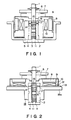
- FIG. 1 of the accompanying drawings shows the deflection scanning rotating apparatus of a laser beam printer using a dynamic fluid bearing.
- a rotary shaft 1 and a sleeve 2 are rotatably fitted to each other, and a thrust plate 3, together with a fixed plate 4, is disposed on the lower end portion of the sleeve 2, and is fixed to an outer cylinder 5.
- a flange 6 is fixed to the rotary shaft 1, and a rotatable polygon mirror 7 for deflecting a light beam from a light source is fixed to the upper portion of the flange 6, and a yoke 9 having a driving magnet 8 fixed thereto is fixed to the lower portion of the flange 6.
- a stator 10 fixed to the outer cylinder 5 is disposed at a location opposed to the driving magnet 8.
- the thrust plate 3 is formed with a shallow groove 11 in the surface thereof opposed to the end portion of the rotary shaft 1, whereby there is formed a dynamic thrust bearing.
- the outer peripheral surface of the rotary shaft 1 is formed with a herringbone-shaped shallow groove 14 at a location thereon opposed to the inner peripheral surface of the sleeve 2, whereby there is formed a dynamic fluid radial bearing.
- a spirally shaped shallow groove 15 along which lubricating fluid flows to the dynamic thrust bearing is formed near the opening portion of the sleeve.
- a recess 16 and a small hole 17 are provided in the sleeve 2 at a location thereon between the herringbone-shaped shallow groove 14 and the spirally shaped shallow groove 15, thereby securing the stability of the dynamic bearings using liquid (oil, grease or the like) as lubricating fluid.
- the present invention has been made in view of the above-noted problems peculiar to the prior art, and intends to reduce the number of parts of a dynamic fluid bearing rotating apparatus and reduce the manufacturing cost thereof and also makes the apparatus compact and light in weight.
- a dynamic fluid bearing rotating apparatus which has a shaft and a sleeve fitted to each other for rotation relative to each other and in which a dynamic radial bearing is constructed between the outer peripheral surface of said shaft and the inner peripheral surface of said sleeve and one end portion of said shaft is received to thereby construct a dynamic thrust bearing, characterized in that of said sleeve and said shaft, the member on the fixed side is made integral with a fixed member formed of a resin material.
- the sleeve or the shaft being made integral with the fixed member formed of a resin material as described above, the number of parts can be reduced and the manufacturing cost can be reduced and also, the apparatus can be made compact and light in weight.
- Figure 1 is a cross-sectional view showing the construction of a dynamic fluid bearing rotating apparatus according to the prior art.
- Figure 2 is a cross-sectional view showing the construction of a dynamic fluid bearing rotating apparatus according to an embodiment of the present invention.
- Figure 3 shows an example of the dynamic fluid bearing rotating apparatus of the present invention as it is used in the polarized scanning apparatus of a laser beam printer.
- Figure 4 is a cross-sectional view showing the construction of a dynamic fluid bearing rotating apparatus according to another embodiment of the present invention.
- Figure 5 is a cross-sectional view showing the construction of a dynamic fluid bearing rotating apparatus according to still another embodiment of the present invention.
- Figure 6 is a cross-sectional view showing the construction of a dynamic fluid bearing rotating apparatus according to yet still another embodiment of the present invention.
- FIG. 2 shows the construction of a dynamic fluid bearing rotating apparatus according to an embodiment of the present invention.
- a rotary shaft 1 and a sleeve 2 are fitted to each other for rotation relative to each other.
- a flange 6 is fixed to the upper portion of the rotary shaft 1
- a rotatable polygon mirror 7 is fixed to the upper portion of the flange 6.
- a herringbone-shaped shallow groove 14 is formed in the rotary shaft 1 at a location thereon whereat the outer peripheral surface of the rotary shaft 1 and the inner peripheral surface of the sleeve 2 are opposed to each other, whereby there is formed a dynamic radial bearing.
- the herringbone-shaped shallow groove 14 is formed in the rotary shaft 1, but alternatively, it may be formed in the sleeve 2.
- a spiral shallow groove 15 along which lubricating fluid flows to the dynamic thrust bearing side (the lower side as viewed in Figure 2) is likewise formed near the opening portion (the upper portion) of the sleeve.
- a rotor 9 having fixed thereto a driving magnet 8 and an FG magnet (a magnet for detecting the rotational speed) 12 is fixed to the lower portion of the flange 6, and a stator coil 10 and a printed substrate 13 on which an FG pattern (a pattern for detecting the rotational speed) is printed are disposed at locations opposed to the driving magnet 8 and the FG magnet 12, respectively.
- the stator coil 10 is disposed on the printed substrate 13 and the electrical energization thereof is controlled by a Hall element, not shown, and a drive circuit and a control circuit formed on the printed substrate 13.
- the sleeve 2 is insert-molded on and made integral with a fixed member 18 formed of a resin material and holding the sleeve 2.
- a thrust plate 3, together with a fixed plate 4, is disposed on the lower end portion of the sleeve 2.
- a shallow groove 11 is formed in that surface of the thrust plate 3 which is opposed to the end portion of the rotary shaft 1, whereby there is formed a dynamic thrust bearing.
- the shallow groove 11 is formed in the thrust plate 3, but alternatively, it may be formed in the end portion of the rotary shaft 1.
- the aforedescribed stator coil 10 and printed substrate 13 are disposed on the upper portion of the fixed member 18, whereby there is constituted a dynamic fluid bearing rotating apparatus as a whole.
- an outer cylinder 5 is made integral with the fixed member 18 formed of resin by insert-molding the sleeve 2, and the printed substrate 13 is disposed on the fixed member 18 formed of resin, and the stator coil 10 is disposed on the printed substrate 13.
- Imaging lenses 22a and 22b are disposed in an optical box 21, and a (dynamic fluid bearing) rotating apparatus constructed like that of Figure 2 is mounted with the underside 18a of the fixed member 18 as a reference.
- a laser beam L emitted from a light source (not shown) is deflected and scanned by the rotatable polygon mirror 7 on the rotating apparatus, and is imaged on the surface of a photosensitive drum 23 by the imaging lenses 22a and 22b.
- the accuracy of the fixed member 18 and of the sleeve 2 insert-molded on the fixed member 18 will be sufficient if it ensures the degree of perpendicularity of the underside 18a of the fixed member 18 to the inner peripheral surface of the sleeve 2. Accordingly, by a doping such a construction, the possibility of causing an incorporation error as in the prior art is eliminated and it becomes possible to reduce the number of parts such as screws and thus, the cost of the apparatus can be reduced.
- a corona discharger for uniformly charging the surface of the photosensitive drum, a developing device for visualizing the electrostatic latent image formed on the surface of the photosensitive drum 23 into a toner image, a transfer corona discharger for transferring the toner image to recording paper (all these being not shown), etc., and by the work of these devices, recording information corresponding to a light beam generated by a light source device is printed on the recording paper.
- FIG 4 shows another embodiment of the present invention.
- members functionally similar to those in Figure 2 are given similar reference numerals and need not be described.
- the sleeve 2 is insert-molded on and made integral with the fixed member 18 formed of a resin material.
- a surface opposed to the end portion of the rotary shaft 1 by the fixed member 18 is formed on the lower end portion of the sleeve 2 and further, a shallow groove 11a is formed in this surface during molding, whereby there is formed a dynamic thrust bearing.
- Figure 5 shows still another embodiment of the present invention.
- the fixed member 18 using a resin material and the sleeve 2 are molded integrally with each other, and a dynamic radial bearing is constituted by the inner peripheral surface 41a of a recess 41 in the fixed member 18 and the outer peripheral surface of the rotary shaft 1.
- the inner peripheral surface 41a of the fixed member 18 opposed to the spirally shaped shallow groove 15 on the rotary shaft 1 is made substantially equal in diameter to a recess 16a formed with a small-diametered aperture 17 so that a mold for molding the fixed member may readily slip out.
- a shallow groove 11a is formed in the bottom surface 41b of the recess 41 so that a dynamic thrust bearing may be formed in opposed relationship with the end portion of the rotary shaft 1.
- the fixed member 18 and the sleeve 2 make one part and thus, it becomes possible to achieve a great reduction in cost and it becomes unnecessary to take the error by assembly into consideration because the accuracy of all parts is determined by one part.
- the accuracy of the inner peripheral surface of the recess in the molded fixed member 18 is insufficient as the dynamic radial bearing surface, the accuracy of that inner peripheral surface can also be maintained by post-working.
- the fixed member 18 with which the sleeve 2 is made integral will make two parts if the portion thereof formed with the shallow groove 11a in which a dynamic thrust bearing is formed is divided, but it will become easy to work and this may become advantageous in terms of cost. There is also the advantage that the materials can be suitably chosen.
- Figure 6 shows the construction of a polygon mirror driving peripherally opposed type motor of the rotatable sleeve type using a dynamic bearing utilizing air as a medium.
- a fixed shaft 32 molded integrally with an outer cylinder 31 which is a fixed member formed of a resin material is formed with a herringbone-shaped groove 33 and a spiral groove 34, and this fixed shaft 32 is also covered with a rotatable sleeve 35 so that the radial gap therebetween may be of the order of 3 - 10 ⁇ .
- a thrust pad 36 which comes into contact with the end of the shaft during the stoppage of the apparatus is forced into the upper end of the sleeve, and a restriction 37 for generating pressure in the thrust direction by the choke effect and causing the rotatable portion to float up to a predetermined level is formed at the center of the thrust pad 36.
- a polygon mirror 38, a magnet 39 as a rotor and a balance ring 40 for keeping the balance of the rotatble member are mounted on the sleeve 35, and a stator coil 41, a Hall element 42 and a reflection type sensor 43 for reading the black-and-white pattern of the balance ring and providing a tack signal for PLL control (phase synchronizing control) are mounted on the outer cylinder in opposed relationship with the magnet 39 and together constitute a PLL control DC (direct current) Hall motor as a whole.
- PLL control phase synchronizing control
- the element important as the dynamic bearing in such a vertical type construction is the thrust pad 36.
- the outer peripheral groove of the shaft and the inner surface of the sleeve are a radial bearing portion having rigidity in the radial direction, whereas the thrust pad 36 works as a thrust bearing portion having thrust rigidity with the aid of the gas pumping action by the restriction 37 and the spiral groove 34.
- the present invention is a dynamic fluid bearing rotating apparatus which has a shaft and a sleeve fitted to each other for rotation relative to each other and in which a dynamic radial bearing is constructed between the outer peripheral surface of said shaft and the inner peripheral surface of said sleeve and one end portion of said shaft is received to constitute a dynamic thrust bearing and wherein of said sleeve and said shaft, the fixed side member is made integral with a fixed member formed of a resin material.
- a rotary shaft type dynamic fluid bearing rotating apparatus there is adopted a construction in which said sleeve is molded integrally with said fixed member and at the same time, a shallow groove for a dynamic thrust bearing is formed in the bottom of said sleeve, the number of parts can be more reduced.
- the sleeve or the shaft is molded integrally with the fixed member formed of a resin material, whereby the number of parts and the manufacturing cost can be reduced and the apparatus can be made compact and light in weight.
Landscapes
- Engineering & Computer Science (AREA)
- General Engineering & Computer Science (AREA)
- Mechanical Engineering (AREA)
- Physics & Mathematics (AREA)
- Fluid Mechanics (AREA)
- Chemical & Material Sciences (AREA)
- Oil, Petroleum & Natural Gas (AREA)
- Sliding-Contact Bearings (AREA)
- Mechanical Optical Scanning Systems (AREA)
Applications Claiming Priority (2)
| Application Number | Priority Date | Filing Date | Title |
|---|---|---|---|
| JP2110359A JPH048909A (ja) | 1990-04-27 | 1990-04-27 | 動圧流体軸受回転装置 |
| JP110359/90 | 1990-04-27 |
Publications (2)
| Publication Number | Publication Date |
|---|---|
| EP0454438A1 true EP0454438A1 (de) | 1991-10-30 |
| EP0454438B1 EP0454438B1 (de) | 1996-07-10 |
Family
ID=14533781
Family Applications (1)
| Application Number | Title | Priority Date | Filing Date |
|---|---|---|---|
| EP91303683A Expired - Lifetime EP0454438B1 (de) | 1990-04-27 | 1991-04-24 | Rotationsapparat, welcher in einem dynamischen Fluid gelagert ist |
Country Status (4)
| Country | Link |
|---|---|
| US (1) | US5466070A (de) |
| EP (1) | EP0454438B1 (de) |
| JP (1) | JPH048909A (de) |
| DE (1) | DE69120722T2 (de) |
Cited By (1)
| Publication number | Priority date | Publication date | Assignee | Title |
|---|---|---|---|---|
| WO1997007584A1 (en) * | 1995-08-14 | 1997-02-27 | Itt Automotive Electrical Systems, Inc. | Windshield wiper motor for use in a vehicle and method for manufacturing |
Families Citing this family (13)
| Publication number | Priority date | Publication date | Assignee | Title |
|---|---|---|---|---|
| JPH07299524A (ja) * | 1994-05-02 | 1995-11-14 | Matsushita Electric Ind Co Ltd | 流体軸受の製造装置 |
| US5927861A (en) * | 1995-03-13 | 1999-07-27 | Matsushita Electric Industrial Co., Ltd. | Motor assembly having ion implantation on sliding surfaces |
| JPH0944985A (ja) * | 1995-07-28 | 1997-02-14 | Matsushita Electric Ind Co Ltd | 動圧軸受装置を使用したディスク駆動装置 |
| JPH0979263A (ja) * | 1995-09-20 | 1997-03-25 | Hitachi Ltd | 軸受装置及びこれを備えたスピンドルモ−タ |
| KR100213880B1 (ko) * | 1996-10-30 | 1999-08-02 | 윤종용 | 유체 유입량을 증가시킨 유체베어링 장치 |
| KR100196929B1 (ko) * | 1996-11-25 | 1999-06-15 | 윤종용 | 간극 편차 보정 유체베어링 장치 |
| JP2000125505A (ja) * | 1998-10-09 | 2000-04-28 | Sankyo Seiki Mfg Co Ltd | モータ |
| KR100968163B1 (ko) | 2002-04-23 | 2010-07-06 | 엔티엔 가부시키가이샤 | 유체 베어링 장치 |
| US7455456B2 (en) | 2003-01-10 | 2008-11-25 | Sony Corporation | Bearing unit and rotation drive device using the same |
| JP5247987B2 (ja) * | 2006-03-09 | 2013-07-24 | Ntn株式会社 | 流体軸受装置 |
| KR20130074573A (ko) * | 2011-12-26 | 2013-07-04 | 삼성전기주식회사 | 유체 동압 베어링 어셈블리 및 이를 포함하는 모터 |
| US9361932B2 (en) * | 2014-10-15 | 2016-06-07 | HGST Netherlands B.V. | Fluid dynamic bearing groove configuration |
| US11835711B2 (en) * | 2019-04-22 | 2023-12-05 | Sri International | Pointing apparatuses and methods involving magnetic-contrast bearings |
Citations (4)
| Publication number | Priority date | Publication date | Assignee | Title |
|---|---|---|---|---|
| DE2922452A1 (de) * | 1978-06-03 | 1979-12-06 | Canon Kk | Laseraufzeichnungseinrichtung |
| US4323317A (en) * | 1980-05-07 | 1982-04-06 | Shibuya Kogyo Company, Ltd. | Pattern controlling device for laser marker |
| DE3101793A1 (de) * | 1981-01-21 | 1982-08-05 | Siemens AG, 1000 Berlin und 8000 München | Schwenkbarer strahlkopf zur umlenkung eines lichtstrahls |
| DE3333368A1 (de) * | 1982-09-16 | 1984-03-22 | Fuji Photo Film Co., Ltd., Minami Ashigara, Kanagawa | Optischer umlaufdrucker |
Family Cites Families (5)
| Publication number | Priority date | Publication date | Assignee | Title |
|---|---|---|---|---|
| US4297713A (en) * | 1978-06-03 | 1981-10-27 | Canon Kabushiki Kaisha | Laser recording apparatus |
| JPS6014615A (ja) * | 1983-07-06 | 1985-01-25 | Ebara Corp | スラスト軸受およびその製造方法 |
| US4875263A (en) * | 1987-02-17 | 1989-10-24 | Nippon Seiko Kabushiki Kaisha | Method of manufacturing a dynamic pressure type slide bearing |
| JP2516967B2 (ja) * | 1987-04-30 | 1996-07-24 | 松下電器産業株式会社 | 軸受装置 |
| US5018880A (en) * | 1988-06-28 | 1991-05-28 | Canon Kabushiki Kaisha | Dynamic pressure bearing device |
-
1990
- 1990-04-27 JP JP2110359A patent/JPH048909A/ja active Pending
-
1991
- 1991-04-24 DE DE69120722T patent/DE69120722T2/de not_active Expired - Fee Related
- 1991-04-24 EP EP91303683A patent/EP0454438B1/de not_active Expired - Lifetime
-
1995
- 1995-04-17 US US08/425,249 patent/US5466070A/en not_active Expired - Fee Related
Patent Citations (4)
| Publication number | Priority date | Publication date | Assignee | Title |
|---|---|---|---|---|
| DE2922452A1 (de) * | 1978-06-03 | 1979-12-06 | Canon Kk | Laseraufzeichnungseinrichtung |
| US4323317A (en) * | 1980-05-07 | 1982-04-06 | Shibuya Kogyo Company, Ltd. | Pattern controlling device for laser marker |
| DE3101793A1 (de) * | 1981-01-21 | 1982-08-05 | Siemens AG, 1000 Berlin und 8000 München | Schwenkbarer strahlkopf zur umlenkung eines lichtstrahls |
| DE3333368A1 (de) * | 1982-09-16 | 1984-03-22 | Fuji Photo Film Co., Ltd., Minami Ashigara, Kanagawa | Optischer umlaufdrucker |
Cited By (2)
| Publication number | Priority date | Publication date | Assignee | Title |
|---|---|---|---|---|
| WO1997007584A1 (en) * | 1995-08-14 | 1997-02-27 | Itt Automotive Electrical Systems, Inc. | Windshield wiper motor for use in a vehicle and method for manufacturing |
| US5770907A (en) * | 1995-08-14 | 1998-06-23 | Itt Automotive Electrical Systems, Inc. | Windshield wiper motor for use in a vehicle and method for manufacturing |
Also Published As
| Publication number | Publication date |
|---|---|
| JPH048909A (ja) | 1992-01-13 |
| DE69120722T2 (de) | 1996-12-12 |
| EP0454438B1 (de) | 1996-07-10 |
| DE69120722D1 (de) | 1996-08-14 |
| US5466070A (en) | 1995-11-14 |
Similar Documents
| Publication | Publication Date | Title |
|---|---|---|
| US5466070A (en) | Dynamic fluid bearing rotating apparatus | |
| US4800401A (en) | Light scanning device for scanning with a lasler beam and an image forming apparatus for forming an image with a laser beam | |
| US5835124A (en) | Dynamic-pressure gas bearing structure and optical deflection scanning apparatus | |
| JPH05683B2 (de) | ||
| EP0581278A2 (de) | Abtastmotor | |
| US6392771B1 (en) | Bearing device and deflecting-scanning apparatus using the same | |
| JP4474064B2 (ja) | 駆動モータ | |
| US6031650A (en) | Light deflecting apparatus and deflection scanning apparatus using the same | |
| US6704038B2 (en) | Light deflecting apparatus | |
| JP2002296532A (ja) | 偏向走査装置 | |
| US6188503B1 (en) | Optical deflector and optical scanner | |
| JP2952086B2 (ja) | 偏向走査装置 | |
| JPS5968716A (ja) | 回転体支持装置 | |
| JP3299654B2 (ja) | 光偏向走査装置 | |
| JPH116975A (ja) | 軸受装置及びそれを用いた偏向走査装置 | |
| JP2000235161A (ja) | 回転駆動装置およびこれを用いた光偏向走査装置 | |
| JP2006221001A (ja) | 偏向走査装置 | |
| JPS5968717A (ja) | 回転多面体鏡装置 | |
| JPS6249318A (ja) | レ−ザ光走査用多面鏡の回転機構 | |
| JPS62266515A (ja) | 光走査用多面鏡の回転機構 | |
| JPH11258537A (ja) | 光偏向走査装置 | |
| JPH1031178A (ja) | 光書き込みユニット | |
| JPS62249122A (ja) | 光走査装置 | |
| JPH11109274A (ja) | 偏向走査装置 | |
| JPH1031179A (ja) | 画像形成装置 |
Legal Events
| Date | Code | Title | Description |
|---|---|---|---|
| PUAI | Public reference made under article 153(3) epc to a published international application that has entered the european phase |
Free format text: ORIGINAL CODE: 0009012 |
|
| AK | Designated contracting states |
Kind code of ref document: A1 Designated state(s): DE FR GB IT |
|
| 17P | Request for examination filed |
Effective date: 19920316 |
|
| 17Q | First examination report despatched |
Effective date: 19940908 |
|
| GRAH | Despatch of communication of intention to grant a patent |
Free format text: ORIGINAL CODE: EPIDOS IGRA |
|
| GRAA | (expected) grant |
Free format text: ORIGINAL CODE: 0009210 |
|
| AK | Designated contracting states |
Kind code of ref document: B1 Designated state(s): DE FR GB IT |
|
| ITF | It: translation for a ep patent filed | ||
| REF | Corresponds to: |
Ref document number: 69120722 Country of ref document: DE Date of ref document: 19960814 |
|
| ET | Fr: translation filed | ||
| PLBE | No opposition filed within time limit |
Free format text: ORIGINAL CODE: 0009261 |
|
| STAA | Information on the status of an ep patent application or granted ep patent |
Free format text: STATUS: NO OPPOSITION FILED WITHIN TIME LIMIT |
|
| 26N | No opposition filed | ||
| REG | Reference to a national code |
Ref country code: GB Ref legal event code: IF02 |
|
| PGFP | Annual fee paid to national office [announced via postgrant information from national office to epo] |
Ref country code: GB Payment date: 20060418 Year of fee payment: 16 |
|
| PGFP | Annual fee paid to national office [announced via postgrant information from national office to epo] |
Ref country code: FR Payment date: 20060426 Year of fee payment: 16 |
|
| PGFP | Annual fee paid to national office [announced via postgrant information from national office to epo] |
Ref country code: IT Payment date: 20060430 Year of fee payment: 16 |
|
| PGFP | Annual fee paid to national office [announced via postgrant information from national office to epo] |
Ref country code: DE Payment date: 20060621 Year of fee payment: 16 |
|
| GBPC | Gb: european patent ceased through non-payment of renewal fee |
Effective date: 20070424 |
|
| PG25 | Lapsed in a contracting state [announced via postgrant information from national office to epo] |
Ref country code: DE Free format text: LAPSE BECAUSE OF NON-PAYMENT OF DUE FEES Effective date: 20071101 |
|
| PG25 | Lapsed in a contracting state [announced via postgrant information from national office to epo] |
Ref country code: GB Free format text: LAPSE BECAUSE OF NON-PAYMENT OF DUE FEES Effective date: 20070424 |
|
| PG25 | Lapsed in a contracting state [announced via postgrant information from national office to epo] |
Ref country code: FR Free format text: LAPSE BECAUSE OF NON-PAYMENT OF DUE FEES Effective date: 20070430 |
|
| PG25 | Lapsed in a contracting state [announced via postgrant information from national office to epo] |
Ref country code: IT Free format text: LAPSE BECAUSE OF NON-PAYMENT OF DUE FEES Effective date: 20070424 |