EP0454558A1 - Mehrfachprotokoll-Umwandler für den Anschluss von mehreren asynchronen Endstellen an ein Fernmeldenetz - Google Patents
Mehrfachprotokoll-Umwandler für den Anschluss von mehreren asynchronen Endstellen an ein Fernmeldenetz Download PDFInfo
- Publication number
- EP0454558A1 EP0454558A1 EP19910401060 EP91401060A EP0454558A1 EP 0454558 A1 EP0454558 A1 EP 0454558A1 EP 19910401060 EP19910401060 EP 19910401060 EP 91401060 A EP91401060 A EP 91401060A EP 0454558 A1 EP0454558 A1 EP 0454558A1
- Authority
- EP
- European Patent Office
- Prior art keywords
- data
- access memory
- terminal
- memory
- converter
- Prior art date
- Legal status (The legal status is an assumption and is not a legal conclusion. Google has not performed a legal analysis and makes no representation as to the accuracy of the status listed.)
- Withdrawn
Links
Images


Classifications
-
- H—ELECTRICITY
- H04—ELECTRIC COMMUNICATION TECHNIQUE
- H04Q—SELECTING
- H04Q11/00—Selecting arrangements for multiplex systems
- H04Q11/04—Selecting arrangements for multiplex systems for time-division multiplexing
- H04Q11/0428—Integrated services digital network, i.e. systems for transmission of different types of digitised signals, e.g. speech, data, telecentral, television signals
-
- H—ELECTRICITY
- H04—ELECTRIC COMMUNICATION TECHNIQUE
- H04L—TRANSMISSION OF DIGITAL INFORMATION, e.g. TELEGRAPHIC COMMUNICATION
- H04L9/00—Cryptographic mechanisms or cryptographic arrangements for secret or secure communications; Network security protocols
- H04L9/40—Network security protocols
Definitions
- the present invention relates to a multi-protocol converter for connecting a plurality of asynchronous terminals to a telecommunications network. It is more particularly applicable to the connection of terminals using asynchronous V24 type links to a data transmission network where the latter are routed via a S2 type communication link defined by the European standard ECMA 104.
- a data transmission network also called a telecommunications network
- a telecommunications network makes it possible to connect a plurality of terminals or stations communicating with each other via a transmission line.
- This is constituted for example by two pairs of telephone wires (one for transmission, the other for reception), which is the case for the S de type link.
- the terminals are also called "terminal data processing equipment" for short, DTE (Data Terminal Equipment, in English, for short, DTE).
- a message consists of a set of elementary information blocks comprising a determined number of binary information. These elementary blocks are called frame. This is structured, includes a start and end message, the address of the terminal for which the message is intended, the address of the sending terminal, the length of the data, the useful data, etc.
- the access rules to the different terminals which govern the dialogue between them define what is commonly called a protocol.
- the latter constitutes a system which orders the conversation between the terminals without prioritizing it.
- HDLC High Level Data Link Control
- a terminal is connected to the transmission line by means of data circuit terminating equipment ETCD (Data Circuit Terminating Equipment, for short), which is a body responsible for particular to adapt the electrical signal delivered by the terminal to the transmission line.
- ETCD Data Circuit Terminating Equipment
- ISDN Integrated Services Digital Network
- the integrated services digital network makes it possible to offer, apart from digital telephony, a wide variety of data processing applications, the transmission of fixed images in particular in the field of fast faxing, and in the near future the possibility to transmit animated images (television, videophone, ).
- ISDN is now used mainly in Europe and in particular in France. Therefore, it includes a number of interfaces standardized according to ECMA standards. For example, for computer communications between computers or terminals and PABX (digital private branch exchanges) the most interesting interface is the so-called S2 interface defined by the European standard ECMA 104. Such an interface is also called communication link of the S2 type. As a physical medium, it uses a telephone transmission line.
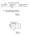
- Figure 1 recalls how such a communication link is made.
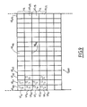
- An LS2 link of this type has a speed of 2,048 megabits per second (or Mbps) and has 32 separate channels, namely 30 type B channels for data transmission with a speed of 64 kbits per second (or even Kbps) , a type D signaling channel at 64 Kbits per second and a frame alignment channel whose bit rate is also 64 Kbits per second.
- the principle of the link LS2 is time multiplexing, each time channel VT0 to VT31 constituting a separate channel. Each time channel corresponds to a time interval IT0, IT1, ..., IT31, each of these intervals making it possible to convey 8 bits b0 to b7.
- time interval IT0 makes it possible to locate the start of each elementary frame TRL, while during the time interval IT16, signaling information is transported making it possible to know the identity and the nature of each correspondent which transmits by the intermediary of a terminal and to deduce therefrom the type of protocol on each of the time channels or channel and the overall load necessary for processing the LS2 link.
- the information messages are transported.
- the information messages are formed by a succession of information frames which can be designated for example by MTR.
- Such a frame is transmitted according to a determined protocol type, for example HDLC, on one of the aforementioned time channels, for example the time channel VT i .
- the corresponding frame MTR i is therefore transmitted in the form of a succession of bytes, on the time channel VT i , within each time interval IT i , and this, every 125 microseconds.
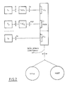
- Figure 2 shows how we can connect according to the prior art a plurality of terminals of different types using for example V24 type links or S0 type to a S2 type link via a PABX private telephone exchange.
- Figure 2 represents an ISDN network.
- This network includes several so-called conventional terminals, such as the two terminals T1 and T2 and a terminal T n of ISDN type.
- the terminal T1 is connected by a link R of type V24 to the PABX automatic switch via an adapter terminal TAD1 and a coupler C1.
- the adapter terminal TAD1 is connected to the coupler C1 via a link of type S0 defined by recommendation I430 of the CCITT.
- the terminal T2 is connected to the PABX automatic switch via the link R of type V24, the adapter terminal TAD2 and a link of a particular type, called PRP, for example, specific to a specific manufacturer, and finally by a C2 coupler.
- PRP a link of a particular type
- the ISDN-type terminal T n is connected by the S0-type link and the coupler C n to the PABX auto-switch.
- the two links R of type V24 making it possible to connect the terminals T1 and T2 to the two adapters TAD1 and TAD2 can be links transmitting with different bit rates which can be for example 1200, 2400, 4800, 9600 or even 19200 bits per second.
- the S0 type link has a speed of 64 kbits per second.
- each constructor which uses a link such as PR, manufactures a coupler such as C2, a coupler which is different from one constructor to another.
- the PABX PABX is connected for example by a S2 type link to an ISDN type digital network, called NNW.
- This network can for example be the network known in France under the name of NUMERIS.
- the PABX can also be connected by a S2 type link to a HOST computer.
- the PABX PABX is connected to a digital network of ISDN type or to a set of computers by a link called primary access AP, which can be of S2 type or more generally a time multiplexed link with a bit rate of 2048 megabits. per second, whose operating principles are similar to those of the S2 link.
- Such connections exist for example in France under the name VN2.
- the present invention makes it possible to remedy these drawbacks by constituting a multi-protocol converter making it possible to connect a plurality of terminals of different types transmitting with different bit rates to a link of the primary access type without necessarily passing through the intermediary of a private automatic branch exchange, and by eliminating the existence of adapter terminals and specialized couplers.
- the converter is extremely fast because it uses a signal processor and a dynamic allocation device making it possible to assign a data channel using a given protocol to a determined physical transmission channel at a given time, the converter comprising n different physical channels .
- the dynamic allocation device allows, on the same physical channel to change the protocol (this change being transparent for the other channels), or to change the physical channel for the same protocol, all without resetting the other channels.
- the multiprotocol converter according to the invention CMP is connected to a plurality of asynchronous terminals T1 to T n , to microcomputers such as the PC computer, to a first computer HOST1, to another computer HOST2. All terminals T1 to T n , PC, HOST1, HOST2 can transmit with different data rates.
- the terminals T1 to T n transmit the data (or receive) by means of asynchronous links of the V24 or X21 type, HOST1 and PC transmit by means of a V24 link, as well as HOST2 via the FRT front-end.
- the converter according to the invention CMP is directly connected to the network RE via a link called primary access AP.
- This primary access can be either a S2 type link allowing the CMP converter to be connected to a PABX automatic switch, or a link such as VN2 allowing it to be connected to an ISDN type network, namely NNW.
- the purpose of the CMP converter is to adapt both the protocols and the different data rates used on all of the R links, to the rate and to the protocols used on the primary access AP. We can say that because of this this converter is practically universal.
- the CMP converter comprises two main functional units, namely, the UCG control and management unit, and the CONV conversion unit.
- the CONV conversion unit is connected on the one hand to type R links and on the other hand to the primary access AP.
- the control and management unit manages the call phases (level 2 and level 3 of the ISO model), that is to say the signaling processing.
- the control and management unit UCG negotiates calls between the various terminals which are directly connected by the links R to the converter CMP and the terminals of the network RE which are connected to the converter via the primary access AP.
- This call phase is carried out according to, for example, the ECMA 105 and 106 standards. It is carried out on channel D (time channel VT16, time intervals IT16).
- the UCG unit also performs the administration of the converter: it is this which defines for a terminal using a given R link, the data channel correspondent which will be used on the primary access as well as the protocol used on this channel. This assignment is transmitted to the conversion unit which processes the corresponding protocol.
- the conversion unit therefore takes care of all the asynchronous R-type channels connected to it, performs the conversion of the data written in V24 into data written in ECMA 102 and vice versa. It can also be said that the conversion unit adapts the data rates and the protocols used on the type R links to the data rate and to the protocols used on the primary access link AP.
- the conversion unit also provides the conventional time multiplexing and demultiplexing functions of the various data channels of the primary access link AP.
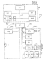
- FIG. 5 shows the essential components of each of the UCG and CONV units.
- the UCG unit further comprises an ADX interface associated with an LDR2 line adapter which makes it possible to connect a synchronous line X21 and therefore a terminal X21 to the control unit and UCG management.
- an X21 link includes 8 lines in parallel carrying the control signals (used during the call phases), these 8 lines being designated by DL1 to DL8. They are connected to the LDR2 line adapter, this LDR2 line adapter being itself connected to the ADX interface. The latter is connected to the internal bus BI1.
- an X21 interface comprises two serial lines, namely LS1 and LS2 which are connected to a serial port of the MPSopr signal microprocessor which constitutes the main element of the CONV1 conversion unit (see below) ).
- the ADX interface is for example of the HM55421 type from the company MATRA HARRIS SEMICONDUCTORS MHS, while the LDR2 line adapters are constituted by elements 3487 and 3486 from the company NATIONAL SEMICONDUCTORS.
- line adapters line drivers
- the two units UCG and CONV communicate with each other via an INT1 interface formed by a set of PAL boxes, more commonly known in English terminology under the term of glue.
- the CONV conversion unit actually consists of two strictly identical and symmetrical conversion units seen from the master processor, CONV1 and CONV2. We will therefore limit our to describing the CONV1 conversion unit.
- the CONV1 conversion unit is built around the MPS1 signal processor.
- the latter is of the TMS 320 C25 type from the company TEXAS INSTRUMENTS. These applications are described as well in the TEXAS INSTRUMENTS book entitled "Digital signal processing applications with the TMS 320 family ", as well as in the TMS 320 C25 users guide.
- This processor is rhythmed by a clock at 40 Mhz, which corresponds to a memory access time of 100 ns.
- the programmable read-only memory MM1 has a memory capacity of 128 Kbytes , while the random access memory MV1, working memory of the signal processor has an access time of 30 ns and a memory capacity of 64 Kbytes.
- the MPS1 processor is connected by the two serial lines LS1 and LS2, for the data, at link X21 (see above) (1 line on transmission, 1 line on reception).
- the signal processor MPS1 has a data bus width BI2 of 16 bits.
- the interface INT1 is therefore designed so as to adapt the data bus BI2 with a width of 16 bits to the internal data bus BI1 of the processor MP which has a width of 32 bits.
- the LDR1 line adapter ensures the electrical adaptation of the voltage levels of V24 lines (+12 and -12 volts) to those of the logic voltage levels of TTL type integrated circuits (0 and 5 volts).
- DAM dual access memory is organized into 64 distinct fifo (first-in, first-out) elements of 16 bytes each, each fifo type element being assigned to a physical channel and to a direction of transmission (transmission or reception) .
- This is particularly visible in Figure 8 which shows in more detail how this dual access memory is made up.
- the latter comprises 32 separate physical channels V0 to V31, each channel comprising a sub-channel (corresponding to a fifo element of 16 bytes) VE reserved for transmission and a second sub-channel VR reserved for reception.
- the physical channel V0 is broken down into two sub-channels VE0 and VR0, the sub-channel VE0 corresponding to the transmission and VR0 to the reception of data.
- the channel V31 comprises two sub-channels VE31 corresponding to the transmission and VR31 corresponding to the reception.
- UART asynchronous couplers are couplers of the "Universal asynchronous receiver / transmitter" type, for example having the reference 2698 B from the company RTC SIGNETICS.
- the UART1 coupler is connected by a serial link of asynchronous type to each of the 16 terminals from which it receives information in the form of groups of 9 to 11 bits, ie 7 to 8 bits (depending on the type of terminal) of data framed by a bit start and 1 or 2 end bits. It transmits them to the master processor (via BI2 and the RAM memory MV) by means of a parallel connection on 7 or 8 bits (the UART coupl coupler therefore only uses part of the BI2 bus which is a 16 bit bus ).
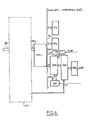
- the interface INT2 between the dynamic allocation device DAD and the primary access link AP is responsible for the shaping of the signals coming either from the dynamic allocation device DAD at transmission or from the primary access link AP on reception . It therefore performs the electrical adaptation of the signals between DAD and AP.
- the transmission medium of the AP connection being assumed to be a telephone line, the interface INT2 is therefore connected to the pair of wires PE for transmission and the pair of wires PR for reception (see FIG. 7). Otherwise, the interface INT2 recovers on each of the time channels VT0 to VT31, a clock signal CLK used both at transmission and at reception, transmits reception DR data to the dynamic allocation device DAD and receives at transmits the DE data coming from it.
- reception synchronization signal SYNR (FIG. 7) consisting of a series of pulses transmitted at successive times t1, t2, etc., ..., separated from each other by an interval of time equal to 125 microseconds which is the duration of an elementary time frame TRL.
- the SYNE synchronization signal on transmission is synchronous with the SYNR signal on reception.
- the components EF 7333 and EF 73321 extract CLK and SYNR and emit SYNE while the component 8075 performs the calculation of CRC4 defined by the CCITT G704 standard making it possible to calculate the error rates on the line S2.
- the clock signal CLK is a square periodic signal which has a frequency of approximately 2.048 Mhz.
- the MMP read-only memory contains the call phase processing program, corresponding to layers 2 and 3 of the ISO module, according to ECMA 105/106 standards.
- This program establishes the dialogue between the UCG unit, on behalf of the CMP converter, and all the terminals of the RE network.
- This dialogue is in fact a negotiation between the converter and all of the terminals of the aforementioned RE network to determine which particular terminal connected to the CMP converter by a V24 or X21 link will exchange information by the AP link with one of the terminals of the RE network subsequently designated by the name of correspondent, and once this has been established, which data channel other than C0 or C16 will be used on the AP link to exchange information between these two terminals.
- the read-only memory MMP also includes a program for controlling the dynamic allocation device DAD, a program making it possible to assign such and such a physical channel of the dual access memory DAM such and such a time channel VT0 to VT31 of the link AP.
- the DUART element is used to control the master processor MP by a special maintenance terminal which allows MP to realize and check everything that happens on each of the physical channels of the conversion unit (DAM and DAD) and also on each of the V24 lines, in particular by examining the status (status) of each of these.
- DAM and DAD physical channels of the conversion unit
- V24 lines V24 lines
- the read-only memory MM1 includes the program making it possible to convert both the data rate and the information protocols from the AP link into the data rate and information protocols which will have to be transmitted via the asynchronous couplers UART1 to the various terminals by the lines V24 or X21.
- This program which is in fact firmware can therefore process several protocols, for example HDLC, ECMA 102, X21, V24 and in addition a special protocol for maintaining a link of the S2 type, a program called BS2 on the one hand.
- the ECMA 102 program for example makes it possible to convert the bit rates which are 64 Kbits per second on each data channel of the AP link into variable bit rates depending on the terminals, for example from 1200 to 19200 bits per second, or even more.
- the processing programs contained in the read-only memory MM1 are transferred to the random access memory MV1 when the CMP converter is powered up.
- the master processor MP negotiates the disconnection phase with the correspondent CO, according to a set of steps 1 ′, 2 ′, 3 ′ similar to steps 1, 2, 3 At the end of step 3 ′, T2 and CO are disconnected.
- the assignment by the dynamic allocation device DAD, under the control of the processor MP, of a physical channel V k , V l , V m , etc., whatever, to a time channel VT i , VT j , etc, ..., is not carried out, in practice, on the arrival of each byte IT i of the same frame of information MTR i nor even when the last byte thereof arrives on the allocation device DAD dynamics.
- the reassignment of a new physical channel different from V k to the time channel VT i takes place only when hundreds or even thousands of frames of type MTR i have passed through the same time channel VT i .
- the reassignment of the channels and consequently the corresponding reprogramming of the dynamic allocation device takes place only when there is a need to change the communication mode.
- the dynamic allocation device DAD performs, under the control of the control and management unit UCG, the dynamic allocation of the different communication time channels on the physical parallel channels of the DAMI dual access memory.
- this dynamic allocation device performs the dynamic allocation of the various terminals of the V24 type on the physical parallel channels of the dual access memory DAM.
- This dynamic allocation of the time channels on the 32 physical channels is carried out according to the configurations, that is to say the needs and loads of the conversation between the various terminals of type V24 granted to the converter according to the invention and the different correspondents of the RE network, these needs and charges being known to the UCG control and management unit.
- This unit comprises, in addition to the elements already mentioned above, the PNT pointer and the DRG data transfer control device.
- the PNT pointer receives the SYNR synchronization signals coming from the interface INT2 on the one hand, and on the other hand, an initial reset signal RESET sent via the bus BI2 by the signal processor MPS1, when the work of the converter CMP begins.
- this pointer which is a modulo 16 counter whose content is incremented by one when it receives a synchronization pulse (SYNR) corresponding to the arrival (in reception) of a time frame TRL is also connected via a parallel link LP on 4 bits to the dual access memory DAM.
- each channel V k (sub-channel VE k and sub-channel VR k ) can contain 16 bytes of information corresponding to 16 successive time frames.
- the 16 bytes in the same path V k are bytes IT i belonging with 16 successive time frames TRL0 to TRL15.
- Each channel V k (and therefore the two sub-channels which compose it) therefore comprises 16 zones each comprising a byte IT i belonging to 1 among 16 successive time frames, these 16 zones having a rank between 0 and 15 and being called VE kq and VR kq . (See figure 9).
- the PNT pointer therefore indicates the rank q of a time frame TRL q among 16 successive frames (between 0 and 15) and therefore the rank of the VE kq (or VR kq ) area where the IT byte is temporarily stored. i of said frame TRL q in the channel V k .
- the DRG regulation device is in fact constituted by a 4-bit up-down counter, which makes it possible to know the filling status of the DAM dual access memory. It receives the synchronization signal (SYNR or SYNE). It is incremented by one each time it receives a synchronization pulse, (and therefore, whenever a frame TRL q arrives at the DAD device) and is decremented by two units each time the signal processor has completed the processing relating to two successive frames TRL q-1 and TRL q .
- the signal processor MPS1 performs processing on 16 bits, ie 2 successive bytes. It can read the content of the DRG counter on its 4 least significant data bits of its data bus (it only uses these to read the content of DRG).
- the signal processor MPS1 resets DRG to zero. As soon as it declares itself ready to work, it authorizes its operation by sending a write signal to a special input thereof (not shown to simplify in FIGS. 6 and 7) via the link L2.
- the processor MPS1 also counts, by means of an internal pointer of software type, the time type frames TRL q which reach it and performs the comparison between the content of its internal counter and the content of the regulation device DRG.
- the processor MPS1 If the content of the regulating device is equal to 15, then the processor MPS1 generates an interrupt towards the master processor MP, via the interface INT1. Everything is then reset to zero, and all of the operations that were in progress and could not be processed by the MPS1 processor must be resumed (both on transmission and on reception).
- DAM memory filled to 3/4 The latter sends a first interrupt signal (via L2) to MPS1.
- This to absorb its delay (which is due to the fact that it does not read and / or write as fast as the bytes reach the dynamic allocation device DAD and in the DAM memory) decides for example to only process signals received. As a rule, its delay is absorbed and the DRG content drops to 4 or 5 (DAM memory empty at 3/4). It generates a second interruption via L2 to MPS1, which resumes its normal work in transmission and reception.
- the content of the DRG counter never exceeds 12 and remains between 1 and 3 (normal traffic).
- the dynamic allocation device DAD receives (or sends to) from the interface INT2, the data signals DRG (signals DE), the synchronization signal SYNR (SYNE) and the clock CLK. It contains a table TAB establishing the correspondence between the time channel VT i and the physical channel V k of the dual access memory DAM. As seen above, this correspondence is established by programming the dynamic allocation device by the master processor MP.
- the DAD device is connected via an 8-bit data bus in parallel, namely BD, from a 5-bit address bus to namely BA and a single-wire LRW link to the DAM dual access memory.
- the address bus BD transmits the data byte corresponding to the time channel VT i
- the address bus BA transmits on 5 bits the address of the physical channel V k of the dual access memory DAM
- the link LRW indicates that it is transmission data or reception data (DR or DE).
- the device DAD writes bytes in DAM on reception (in the sub-channel VR k ) and comes to read these on transmission (in the sub-channel VE k ).
- the SYNR synchronization signal arrives on PNT, DAD and DR.
- the content of PRT goes from 0 to 1. That of DRG goes from 0 to 1.
- the IT byte i 0 is transmitted in series (after having been reshaped by the interface INT2 to the DAD device).
- the table TAB then contains the number k of the physical channel V k , the sub-channel VR k of which will contain the byte IT i 0 which will go to the area VR k0 . This table therefore establishes the correspondence between i and k.
- the address bus BA then transmits the value k to the memory DAM when it receives the byte IT i 0.
- the latter is stored inside registers (not shown for simplicity in FIGS. 6 and 7) of DAD series-parallel type, the time required to transform it from serial byte to parallel byte. It is then written by DAD in the area VR k0 of the dual access memory DAM. During this time the line LP then transmits on 4 bits the value 0 which is the number of the area VR k0 containing the byte IT i 0 (this value 0 corresponds to the number 0 of the frame TRL0).
- a similar reasoning can be made for the byte IT j 0 written by the dynamic allocation device DAD in the area VR l0 of the sub-channel VR l belonging to the channel V l which is assigned to the time channel VT j by the MP processor.
- DAD comes to read what is contained in the areas VE k0 and VE l0 of the sub- channels VE k and VE l where the processor MPS1 is assumed to have written bytes belonging to transmission frames sent by any of the terminals connected to the converter CMP. In fact, immediately after the reinitialization, the latter writes nothing in the dual access memory as long as the content of DR is not equal to 3. Therefore, DAD reads zones VE k0 and VE l0 whose content is considered empty.
- DAD writes the bytes IT i 1 and IT j 1 in the areas VR k1 and VR l1 , DAD reading what is supposed to be writes to areas VE k1 and VE l1 , and therefore reads empty content.
- DAD writes the bytes IT i 2 and IT j 2 to VR k2 and VR l2 and reads what is supposed to be written in the areas VE k2 and VE l2 and consequently empty content.
- MPS1 reads DRG, it finds that its content is equal to 3 and therefore knows that two bytes, IT i 0, IT i 1, IT j 0, IT j 1, etc, ... have arrived and are coming read these. It processes them according to the transmission protocol used for MTR i and MTR j and stores them in the RAM before transmitting them to the terminals for which they are intended, via asynchronous UART couplers.
- MPS1 then writes 2 bytes of information TI i 0 and TI j 0 belonging to 2 information frames sent for example by two terminals connected to the CMP converter, these frames being called TMR i and TMR j , in the areas VE k0 and VE l0 of DAM and the next 2 bytes TI i 1 and TI j 1 belonging to the same frames in the areas VE k1 and VE l1 .
- the processor MPS1 decrements by 2 the content of DRG (which then goes to 1) and keeps in memory (by its internal pointer that it has read) what was contained in VR k0 -VR k1 , VR l0 -VR l1 .
- IT i 16-IT j 16 will be written in VR k0 -VR l0 and so on, the process reproduces identical to itself.
Landscapes
- Engineering & Computer Science (AREA)
- Computer Security & Cryptography (AREA)
- Computer Networks & Wireless Communication (AREA)
- Signal Processing (AREA)
- Communication Control (AREA)
Applications Claiming Priority (2)
| Application Number | Priority Date | Filing Date | Title |
|---|---|---|---|
| FR9005142 | 1990-04-23 | ||
| FR909005142A FR2661300B1 (fr) | 1990-04-23 | 1990-04-23 | Convertisseur multiprotocoles de raccordement d'une pluralite de terminaux asynchrones a un reseau de telecommunications. |
Publications (1)
| Publication Number | Publication Date |
|---|---|
| EP0454558A1 true EP0454558A1 (de) | 1991-10-30 |
Family
ID=9395984
Family Applications (1)
| Application Number | Title | Priority Date | Filing Date |
|---|---|---|---|
| EP19910401060 Withdrawn EP0454558A1 (de) | 1990-04-23 | 1991-04-22 | Mehrfachprotokoll-Umwandler für den Anschluss von mehreren asynchronen Endstellen an ein Fernmeldenetz |
Country Status (2)
| Country | Link |
|---|---|
| EP (1) | EP0454558A1 (de) |
| FR (1) | FR2661300B1 (de) |
Cited By (5)
| Publication number | Priority date | Publication date | Assignee | Title |
|---|---|---|---|---|
| AU641586B2 (en) * | 1991-03-11 | 1993-09-23 | Alcatel N.V. | Protocol adaptation in telecommunications terminal |
| WO1995023492A1 (en) * | 1994-02-23 | 1995-08-31 | Harris Corporation | Multi-processing and direct routing of signalling protocols in voice communication channels |
| AU706106B2 (en) * | 1997-02-28 | 1999-06-10 | Samsung Electronics Co., Ltd. | Method for configuring network interface circuit in integrated services digital network keyphone system |
| US6047319A (en) * | 1994-03-15 | 2000-04-04 | Digi International Inc. | Network terminal server with full API implementation |
| CN114374746A (zh) * | 2021-12-22 | 2022-04-19 | 中国人民解放军空军通信士官学校 | 一种基于cdp协议的以太网网络接口转换器 |
Citations (4)
| Publication number | Priority date | Publication date | Assignee | Title |
|---|---|---|---|---|
| EP0100092A2 (de) * | 1982-07-27 | 1984-02-08 | CSELT Centro Studi e Laboratori Telecomunicazioni S.p.A. | Vielfachübertragungsschnittstelle zwischen einem Prozessor und digitalen Übertragungseinrichtungen |
| EP0250075A2 (de) * | 1986-06-20 | 1987-12-23 | Nortel Networks Corporation | ISDN-D-Kanal-Bearbeitungsvorrichtung |
| US4821265A (en) * | 1987-04-06 | 1989-04-11 | Racal Data Communications Inc. | Node architecture for communication networks |
| EP0377350A1 (de) * | 1988-12-27 | 1990-07-11 | Bull S.A. | Mehrfachprotokoll-ISDN-Übertragungssteuerung |
-
1990
- 1990-04-23 FR FR909005142A patent/FR2661300B1/fr not_active Expired - Fee Related
-
1991
- 1991-04-22 EP EP19910401060 patent/EP0454558A1/de not_active Withdrawn
Patent Citations (4)
| Publication number | Priority date | Publication date | Assignee | Title |
|---|---|---|---|---|
| EP0100092A2 (de) * | 1982-07-27 | 1984-02-08 | CSELT Centro Studi e Laboratori Telecomunicazioni S.p.A. | Vielfachübertragungsschnittstelle zwischen einem Prozessor und digitalen Übertragungseinrichtungen |
| EP0250075A2 (de) * | 1986-06-20 | 1987-12-23 | Nortel Networks Corporation | ISDN-D-Kanal-Bearbeitungsvorrichtung |
| US4821265A (en) * | 1987-04-06 | 1989-04-11 | Racal Data Communications Inc. | Node architecture for communication networks |
| EP0377350A1 (de) * | 1988-12-27 | 1990-07-11 | Bull S.A. | Mehrfachprotokoll-ISDN-Übertragungssteuerung |
Non-Patent Citations (3)
| Title |
|---|
| COMPUTER DESIGN. vol. 28, no. 19, 01 octobre 1989, LITTLETON, MASSACHUS pages 28 - 32; R.Wilson: "Communications controllers search for higher integration" * |
| ELECTRO vol. 8, no. 13/1, 1983, LOS ANGELES US pages 1 - 7; S.Wilder: "An Applications Oriented Approach to Office Automation" * |
| JAPAN TELECOMMUNICATION REVIEW. vol. 25, no. 4, octobre 1983, TOKYO JP pages 275 - 282; S.Tomita: "Improved D50 Circuit Switching System" * |
Cited By (6)
| Publication number | Priority date | Publication date | Assignee | Title |
|---|---|---|---|---|
| AU641586B2 (en) * | 1991-03-11 | 1993-09-23 | Alcatel N.V. | Protocol adaptation in telecommunications terminal |
| WO1995023492A1 (en) * | 1994-02-23 | 1995-08-31 | Harris Corporation | Multi-processing and direct routing of signalling protocols in voice communication channels |
| US6047319A (en) * | 1994-03-15 | 2000-04-04 | Digi International Inc. | Network terminal server with full API implementation |
| AU706106B2 (en) * | 1997-02-28 | 1999-06-10 | Samsung Electronics Co., Ltd. | Method for configuring network interface circuit in integrated services digital network keyphone system |
| CN114374746A (zh) * | 2021-12-22 | 2022-04-19 | 中国人民解放军空军通信士官学校 | 一种基于cdp协议的以太网网络接口转换器 |
| CN114374746B (zh) * | 2021-12-22 | 2023-12-08 | 中国人民解放军空军通信士官学校 | 一种基于cdp协议的以太网网络接口转换器 |
Also Published As
| Publication number | Publication date |
|---|---|
| FR2661300A1 (fr) | 1991-10-25 |
| FR2661300B1 (fr) | 1994-06-17 |
Similar Documents
| Publication | Publication Date | Title |
|---|---|---|
| EP0377350B1 (de) | Mehrfachprotokoll-ISDN-Übertragungssteuerung | |
| EP0034514B1 (de) | Digitale Zeitvielfach-Vermittlungsanlage für Leitungen mit Sprach- und Datenpaketübertragungen | |
| EP0036808B1 (de) | Konzentrator für Kommunikationssystem zum Anschliessen mehrerer asynchroner Telematik-Terminals | |
| EP0374828A1 (de) | Fernsprech-Anschlussanordnung für einen Personal-Computer und eine Einrichtung dafür | |
| EP0048781A1 (de) | Leitungssteuerung für einen Vorschaltrechner in einem Datennetz | |
| FR2589657A1 (fr) | Procede de transmission de pages de document dans un terminal telematique | |
| WO1995013676A1 (fr) | Systeme de communication avec un reseau incluant un ensemble d'administration | |
| EP0454558A1 (de) | Mehrfachprotokoll-Umwandler für den Anschluss von mehreren asynchronen Endstellen an ein Fernmeldenetz | |
| EP0179715B1 (de) | Schnittstellenanordnung zum Anschluss einer digitalen Einrichtung an eine Zeitmultiplexverbindung | |
| WO1997027714A1 (fr) | Terminal voix-donnees pour reseau telephonique radio | |
| EP0161162B1 (de) | Automatische Vermittlungsanlage mit Video-Schaltmatrix | |
| FR2585909A1 (fr) | Procede de transmission de donnees par paquets a travers un reseau ou une chaine de transmission, et dispositif de mise en oeuvre | |
| EP1180318B1 (de) | Teilnehmerinnenvorrichtung mit mehreren atm-endeinrichtungen | |
| EP0966805A1 (de) | Verfahren zur datenübertragung zwischen datenverarbeitenden mitteln und einem radiokommunikationsnetz und modul und mobiles endgeräat zur durchführung des verfahrens | |
| FR2785408A1 (fr) | Procede et dispositif de communication d'information numerique et appareils les mettant en oeuvre | |
| FR2472319A1 (fr) | Station d'abonne multiservice | |
| EP0470875A1 (de) | Fernmeldesteuerungsanordnung zwischen einem Rechner und einer Mehrheit von ISDN-artigen Endgeräten | |
| KR0153956B1 (ko) | 에이티엠 정합 계층중 타입 5 경로를 통해 오디오/비쥬얼 다중화 신호를 전송하기 위한 장치 및 방법 | |
| EP0614590B1 (de) | Telematisches Terminal mit voller oder reduzierter wirksamer Informationsabgabe | |
| CA2113326A1 (fr) | Systeme de traitement de signalisation pour ensemble support de mode circuit d'une installation de telecommunications | |
| EP0112952A1 (de) | Vielfachverbindungssystem für Teilnehmerstationen | |
| EP0530098B1 (de) | Verfahren und Anordnung für Nachrichtenübertragung zwischen Geräten einer Kommunikationsanlage | |
| EP0711064B1 (de) | Schalten eines Endgeräts, wie Faksimilegerät, auf einen von zwei Kanälen | |
| EP1152634B1 (de) | Verbindungsanlage zwischen einer ISDN Teilnehmereinrichtung und einem IP/ATM Netzwerk | |
| BE888019R (fr) | Montage de transmission de donnees |
Legal Events
| Date | Code | Title | Description |
|---|---|---|---|
| PUAI | Public reference made under article 153(3) epc to a published international application that has entered the european phase |
Free format text: ORIGINAL CODE: 0009012 |
|
| 17P | Request for examination filed |
Effective date: 19910816 |
|
| AK | Designated contracting states |
Kind code of ref document: A1 Designated state(s): CH DE FR GB IT LI |
|
| RAP3 | Party data changed (applicant data changed or rights of an application transferred) |
Owner name: BULL S.A. |
|
| 17Q | First examination report despatched |
Effective date: 19940406 |
|
| STAA | Information on the status of an ep patent application or granted ep patent |
Free format text: STATUS: THE APPLICATION IS DEEMED TO BE WITHDRAWN |
|
| 18D | Application deemed to be withdrawn |
Effective date: 19940809 |