EP0454570A1 - Antibetrugseinrichtung für Leser tragbarer Objekte, welche einen elektronischen Schaltkreis zum Speichern umfassen - Google Patents
Antibetrugseinrichtung für Leser tragbarer Objekte, welche einen elektronischen Schaltkreis zum Speichern umfassen Download PDFInfo
- Publication number
- EP0454570A1 EP0454570A1 EP91401079A EP91401079A EP0454570A1 EP 0454570 A1 EP0454570 A1 EP 0454570A1 EP 91401079 A EP91401079 A EP 91401079A EP 91401079 A EP91401079 A EP 91401079A EP 0454570 A1 EP0454570 A1 EP 0454570A1
- Authority
- EP
- European Patent Office
- Prior art keywords
- reader
- circuit
- electromagnetic field
- portable object
- sampling
- Prior art date
- Legal status (The legal status is an assumption and is not a legal conclusion. Google has not performed a legal analysis and makes no representation as to the accuracy of the status listed.)
- Withdrawn
Links
Images


Classifications
-
- G—PHYSICS
- G06—COMPUTING OR CALCULATING; COUNTING
- G06K—GRAPHICAL DATA READING; PRESENTATION OF DATA; RECORD CARRIERS; HANDLING RECORD CARRIERS
- G06K7/00—Methods or arrangements for sensing record carriers, e.g. for reading patterns
- G06K7/0013—Methods or arrangements for sensing record carriers, e.g. for reading patterns by galvanic contacts, e.g. card connectors for ISO-7816 compliant smart cards or memory cards, e.g. SD card readers
- G06K7/0086—Methods or arrangements for sensing record carriers, e.g. for reading patterns by galvanic contacts, e.g. card connectors for ISO-7816 compliant smart cards or memory cards, e.g. SD card readers the connector comprising a circuit for steering the operations of the card connector
-
- G—PHYSICS
- G06—COMPUTING OR CALCULATING; COUNTING
- G06K—GRAPHICAL DATA READING; PRESENTATION OF DATA; RECORD CARRIERS; HANDLING RECORD CARRIERS
- G06K7/00—Methods or arrangements for sensing record carriers, e.g. for reading patterns
- G06K7/0013—Methods or arrangements for sensing record carriers, e.g. for reading patterns by galvanic contacts, e.g. card connectors for ISO-7816 compliant smart cards or memory cards, e.g. SD card readers
- G06K7/0021—Methods or arrangements for sensing record carriers, e.g. for reading patterns by galvanic contacts, e.g. card connectors for ISO-7816 compliant smart cards or memory cards, e.g. SD card readers for reading/sensing record carriers having surface contacts
-
- G—PHYSICS
- G06—COMPUTING OR CALCULATING; COUNTING
- G06K—GRAPHICAL DATA READING; PRESENTATION OF DATA; RECORD CARRIERS; HANDLING RECORD CARRIERS
- G06K7/00—Methods or arrangements for sensing record carriers, e.g. for reading patterns
- G06K7/0013—Methods or arrangements for sensing record carriers, e.g. for reading patterns by galvanic contacts, e.g. card connectors for ISO-7816 compliant smart cards or memory cards, e.g. SD card readers
- G06K7/0086—Methods or arrangements for sensing record carriers, e.g. for reading patterns by galvanic contacts, e.g. card connectors for ISO-7816 compliant smart cards or memory cards, e.g. SD card readers the connector comprising a circuit for steering the operations of the card connector
- G06K7/0091—Methods or arrangements for sensing record carriers, e.g. for reading patterns by galvanic contacts, e.g. card connectors for ISO-7816 compliant smart cards or memory cards, e.g. SD card readers the connector comprising a circuit for steering the operations of the card connector the circuit comprising an arrangement for avoiding intrusions and unwanted access to data inside of the connector
Definitions
- the present invention relates to an anti-fraud device for portable object readers each provided with an electronic circuit for storing identification data.
- the present invention applies in particular to portable objects known under the name of "memory cards” or even “smart cards” and which comprise a card of the bank or telephone card type, provided with an integrated circuit used to store, between others, identification data.
- portable objects known under the name of "memory cards” or even “smart cards” and which comprise a card of the bank or telephone card type, provided with an integrated circuit used to store, between others, identification data.
- the invention also applies to other types of portable object, such as badges, keys, pens, and so on, each provided with such a circuit.
- memory card readers are not protected against fraudsters who try, sometimes successfully, to lure the reader processing circuits using a laptop computer connected by one or more wires, to the contacts of the electronic circuit of a card.
- the portable computer is in communication with the processing circuits of the reader, which allows the fraudster to deceive the latter, and to be authorized operations not allowed.
- the present invention aims to overcome the above drawback, by providing an anti-fraud device which makes it possible to detect, when a card or the like is inserted into a reader, the presence of a conductive connection between the contacts of the electronic circuit. from the card and outside the reader.
- any conductive connection which crosses the cavity behaves like an antenna on reception and captures part of the energy of the high-frequency field.
- This energy gives rise to a signal at the frequency of the electromagnetic field among the sampled signals.
- the presence of such a signal means that a connection crosses the cavity.
- the detection of this signal is therefore followed by the inhibition of the processing circuit, and possibly the triggering of an alarm.
- high frequency is meant here the frequency range whose wavelengths in the air are decimetric, metric and decametric, that is to say the range between substantially 10 MHz and substantially 1 GHz.
- said high frequency electromagnetic field is modulated by a low frequency signal
- said detection means comprise means for demodulating the signal at the frequency of said electromagnetic field and means for detecting the low frequency signal.
- the electronic detection circuits are simple and of relatively low cost.
- the frequency of said electromagnetic field is variable over time.
- This feature makes it possible to foil the maneuvers of a fraudster who would try to disrupt the operation of the anti-fraud device using an oscillating circuit tuned to the frequency of the electromagnetic field, which would be connected to the parasitic connection to attenuate the useful signal at the frequency of the electromagnetic field.
- the dimensions of the orifices for the passage of said portable object through the walls of said cavity are such that said electromagnetic field can pass through these orifices only undergoing strong attenuation.
- the dimensions of the orifices are chosen so that these, while allowing the passage of the portable object, behave, with respect to the electromagnetic field, like sections of waveguides below the cutoff, therefore strongly attenuating the field which traverses them.
- the signal at the frequency of the field which is among the signals picked up comes only from the presence of the fraudulent connection, which improves the signal to noise ratio of the device.
- the electromagnetic field which could be radiated outside the cavity is then negligible.
- said sampling means comprise a plurality of sampling contacts each cooperating with a contact of said electronic circuit
- said detection means comprise a single detection circuit provided with a connected input, via a plurality of capacitors, at each of said sampling contacts.
- This embodiment is simple and economical.
- said detection means comprise as many detection circuits as there are sampling contacts, the input of each detection circuit being connected to a sampling contact and its output to an input of a single summing circuit.
- said removal means comprise a loop arranged in the vicinity of said electronic circuit when said portable object is introduced into the reader.
- the device of the invention makes it possible to detect the presence of a conductive connection between the contacts connected to the processing circuits of the reader and the external environment, connection which allows a fraudster to deceive these circuits, using a laptop for example.
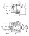
- the anti-fraud device 1 comprises a housing 10, here metallic, the interior volume of which is partitioned into three cavities 11, 14 and 15.
- the housing 10 comprises, on the side directed towards the user of the reader, an orifice, in this case a slot 12, which allows the insertion of the card 2 of the user.
- the slot 12 opens into the cavity 11, which comprises, in the wall opposite to that in which the slot 12 is made, a slot 13 identical opening into the cavity 15.
- a sampling device 3 provided with an insertion slot 32.
- the card 2 of the user comprises an integrated electronic circuit 21 provided with a plurality of access contacts, and intended to memorize at least identification data.
- the sampling device is of the known type which comprises as many flexible blades as there are access contacts to the electronic circuit 21, each flexible blade forming a sampling contact which comes to cooperate with an access contact corresponding to the circuit 21 when the card 2 is inserted in the withdrawal device 3.
- the flexible blades are not visible in FIG. 1, but they are shown diagrammatically in FIGS. 2, 3 and 4 where they bear the reference 31.
- a cavity 14, contiguous to the cavity 11, is intended to receive a high frequency oscillator 7, the frequency of which is here equal to 100 MHz.
- the output signal from the oscillator 7 is applied to an antenna, comprising a conductive track 71 deposited on an insulating substrate 72.
- the insulating substrate 72 is the size of the cavity 11 and comes, in normal operation, to cover it.
- the conductive track 71 is here in spiral shape which extends over the entire surface of the substrate 72.
- a cover 9 closes the housing 10.
- the oscillator 7 and the antenna 71 cause a high frequency electromagnetic field, here at 100 MHz, to reign inside the cavity 11.
- a fraudster introduces a card 2 onto which he has welded a conductive connection 25 connected for example to a laptop computer not shown, this connection 25 necessarily passes through the cavity 11, owing to the fact that the latter is disposed upstream of the sampling device 3 on the card insertion path 2.
- connection 25 forms an antenna, captures part of the energy of the electromagnetic field in the cavity 11, and this results in a signal at 100 MHz on the sampling contact 31 which cooperates with the access contact to the circuit 21 connected to the connection 25. To detect the presence of this connection 25, it is therefore sufficient to search for a signal at 100 MHz among the signals sampled by the sampling contacts 31. If such a signal is detected, the processing circuits are inhibited of the reader, normally intended to authorize, after verification of the identification data, an operation such as withdrawing money, for example. If necessary, an alarm is triggered.
- the electromagnetic field remains confined to the interior of the cavity 11 despite the orifices 12 and 13, because these are of dimensions significantly less than half the wavelength, and are formed in relatively thick walls. They therefore behave, for the electromagnetic field, like waveguides far below their low cutoff frequency. As a result, the latter can only pass through these orifices 12 and 13 by undergoing strong attenuation.
- the portable object is not a card, but a key or a cylindrical object, the above conditions remain easy to respect, as long as the dimensions of the portable object remain reasonable.
- the wall which separates the cavities 11 and 15 has a role of an electromagnetic screen intended to prevent the field which reigns in the cavity 11 from reaching the cavity 15 other than through the connection 25 forming the antenna.
- the wall which separates the cavities 11 and 14 has a simple role of mechanical barrier, to protect the oscillator 7 from various objects capable of being introduced through the orifice 12.
- the output signal from the oscillator 7 is amplitude modulated by a low frequency signal, that is to say the frequency here is less than substantially 100 kHz.
- the circuit 8 comprises a single preamplification and demodulation circuit 52 provided with an input connected, via a plurality of capacitors 51, to each pick contacts 31.
- Each of the sampling contacts 31 is also connected to the processing circuit 4 which has been discussed and which is intended, in normal operation, to check the data stored in the circuit 21.
- the circuit 52 is followed by a circuit 54 for detecting the low frequency signal which was used to modulate the output signal from the oscillator 7.
- the output of the circuit 54 is connected to an inhibition input of the processing circuit 4.
- the presence of the capacitors 51, all connected to the input of the circuit 52, can however introduce a coupling between the signals picked up, detrimental to the proper functioning of the processing circuit 4, even in the no connection 25.
- the embodiment of Figure 3 does not suffer from this drawback. To this end, it comprises as many circuits 52 as there are sampling contacts 31, the input of each circuit 52 being connected to a corresponding sampling contact 31, and its output being connected to one of the inputs of a summing circuit 53, followed by circuit 54 already described, itself connected to circuit 4 not shown for the sake of simplicity. In this case, there is no parasitic coupling between the sampling contacts and the circuit 4 operates as in the absence of anti-fraud device.
- the sampling device 3 comprises a loop 55 forming an antenna, arranged in the vicinity of the circuit 21 when the card 2 is inserted into the reader. In this case, there is no contact between the loop 55 and the sampling contacts 31.
- the loop 55 is followed by circuits 52 and 54 as in the case of FIG. 1.
- the scope of the present application is not limited to the embodiment which has just been described.
- the modulation of the electromagnetic field in the cavity 11 facilitates the subsequent detection of the signal brought back by the connection 25, this is not compulsory, and one could also use an unmodulated high frequency field, by directly detecting the signal at the field frequency, possibly after high frequency amplification.
- connection 25 does not have to be metallic to be detected. Thus, even if it is made of carbon, or using a conductive paint, the anti-fraud device of the invention remains effective.
Landscapes
- Engineering & Computer Science (AREA)
- Artificial Intelligence (AREA)
- Computer Vision & Pattern Recognition (AREA)
- Physics & Mathematics (AREA)
- General Physics & Mathematics (AREA)
- Theoretical Computer Science (AREA)
- Burglar Alarm Systems (AREA)
Applications Claiming Priority (2)
| Application Number | Priority Date | Filing Date | Title |
|---|---|---|---|
| FR9005258 | 1990-04-25 | ||
| FR909005258A FR2661531B1 (fr) | 1990-04-25 | 1990-04-25 | Dispositif anti-fraude pour lecteur d'objets portatifs pourvus chacun d'un circuit electronique de memorisation. |
Publications (1)
| Publication Number | Publication Date |
|---|---|
| EP0454570A1 true EP0454570A1 (de) | 1991-10-30 |
Family
ID=9396065
Family Applications (1)
| Application Number | Title | Priority Date | Filing Date |
|---|---|---|---|
| EP91401079A Withdrawn EP0454570A1 (de) | 1990-04-25 | 1991-04-23 | Antibetrugseinrichtung für Leser tragbarer Objekte, welche einen elektronischen Schaltkreis zum Speichern umfassen |
Country Status (2)
| Country | Link |
|---|---|
| EP (1) | EP0454570A1 (de) |
| FR (1) | FR2661531B1 (de) |
Cited By (3)
| Publication number | Priority date | Publication date | Assignee | Title |
|---|---|---|---|---|
| US5412318A (en) * | 1992-03-17 | 1995-05-02 | Landis & Gyr Business Support Ag | Device for detecting attempts at fraud on an apparatus for reading and writing on a chip card |
| EP0945822A3 (de) * | 1998-03-26 | 2000-06-28 | Ncr International Inc. | Kartenleser |
| WO2007134418A1 (en) * | 2006-05-24 | 2007-11-29 | Banco Bradesco S.A. | Operation abnormality detector of electronic modules |
Citations (5)
| Publication number | Priority date | Publication date | Assignee | Title |
|---|---|---|---|---|
| EP0022390A1 (de) * | 1979-06-26 | 1981-01-14 | Imphy S.A. | Verfahren zum Kennzeichnen und Erkennen von Gegenständen, die durch elektrisch leitende Elemente gekennzeichnet sind |
| US4388524A (en) * | 1981-09-16 | 1983-06-14 | Walton Charles A | Electronic identification and recognition system with code changeable reactance |
| FR2554262A1 (fr) * | 1983-10-28 | 1985-05-03 | Flonic Sa | Dispositif anti-fraude pour lecteur de cartes a memoire electronique |
| EP0183523A2 (de) * | 1984-11-26 | 1986-06-04 | Toyota Jidosha Kabushiki Kaisha | Fahrzeugantennensystem |
| FR2646260A1 (fr) * | 1989-04-19 | 1990-10-26 | Dassault Electronique | Lecteur de carte a microcircuit perfectionne |
-
1990
- 1990-04-25 FR FR909005258A patent/FR2661531B1/fr not_active Expired - Lifetime
-
1991
- 1991-04-23 EP EP91401079A patent/EP0454570A1/de not_active Withdrawn
Patent Citations (5)
| Publication number | Priority date | Publication date | Assignee | Title |
|---|---|---|---|---|
| EP0022390A1 (de) * | 1979-06-26 | 1981-01-14 | Imphy S.A. | Verfahren zum Kennzeichnen und Erkennen von Gegenständen, die durch elektrisch leitende Elemente gekennzeichnet sind |
| US4388524A (en) * | 1981-09-16 | 1983-06-14 | Walton Charles A | Electronic identification and recognition system with code changeable reactance |
| FR2554262A1 (fr) * | 1983-10-28 | 1985-05-03 | Flonic Sa | Dispositif anti-fraude pour lecteur de cartes a memoire electronique |
| EP0183523A2 (de) * | 1984-11-26 | 1986-06-04 | Toyota Jidosha Kabushiki Kaisha | Fahrzeugantennensystem |
| FR2646260A1 (fr) * | 1989-04-19 | 1990-10-26 | Dassault Electronique | Lecteur de carte a microcircuit perfectionne |
Cited By (6)
| Publication number | Priority date | Publication date | Assignee | Title |
|---|---|---|---|---|
| US5412318A (en) * | 1992-03-17 | 1995-05-02 | Landis & Gyr Business Support Ag | Device for detecting attempts at fraud on an apparatus for reading and writing on a chip card |
| US5510720A (en) * | 1992-03-17 | 1996-04-23 | Landis & Gyr Business Support Ag | Device for detecting attempts at fraud on an apparatus for reading and writing on a chip card |
| EP0945822A3 (de) * | 1998-03-26 | 2000-06-28 | Ncr International Inc. | Kartenleser |
| US6196463B1 (en) | 1998-03-26 | 2001-03-06 | Ncr Corporation | Card reader |
| WO2007134418A1 (en) * | 2006-05-24 | 2007-11-29 | Banco Bradesco S.A. | Operation abnormality detector of electronic modules |
| US7965194B2 (en) | 2006-05-24 | 2011-06-21 | Banco Bradesco S.A. | Operation abnormality detector of electronic modules, particularly a card reader in a self-serving bank machine |
Also Published As
| Publication number | Publication date |
|---|---|
| FR2661531A1 (fr) | 1991-10-31 |
| FR2661531B1 (fr) | 1994-09-30 |
Similar Documents
| Publication | Publication Date | Title |
|---|---|---|
| EP1918859B1 (de) | Device for protection against fraud in contactless communication objects | |
| EP0374018B1 (de) | Einrichtung zum Fernaustausch von Informationen zwischen einem tragbaren Objekt und einer Station | |
| FR2914518A1 (fr) | Systeme de communication securisee entre un lecteur de carte sans contact et une carte. | |
| EP2057588A1 (de) | In kontaktloses objekt in form eines sicheren dokuments mit rfid integriertes sicheres peripheriegerät | |
| EP1794918B1 (de) | Sichere kontaktlose kommunikationsvorrichtung und verfahren | |
| FR2964778A1 (fr) | Dispositif de protection d'un connecteur et d'un fil de communication d'un lecteur de carte a memoire. | |
| FR2554262A1 (fr) | Dispositif anti-fraude pour lecteur de cartes a memoire electronique | |
| CA2657699A1 (fr) | Dispositif d'identification par radiofrequence (rfid) appose sur un objet a identifier | |
| CA3003618C (fr) | Corps de lecteur de carte a memoire a treillis de protection recto-verso | |
| EP0454570A1 (de) | Antibetrugseinrichtung für Leser tragbarer Objekte, welche einen elektronischen Schaltkreis zum Speichern umfassen | |
| EP0177394B1 (de) | Überwachungssystem für Behälter mit ultraschallprüfbarem Verschluss unter Verwendung eines unabhängigen Anschlusselements | |
| EP1087332B1 (de) | Transponder für unterschiedliche Einsatzzwecke | |
| EP1904960B1 (de) | Einrichtung zur bereitstellung aktiver sicherheit für eine kontaktfreie elektronische einrichtung | |
| FR2797072A1 (fr) | Circuit pour detecter la presence ou l'absence d'un dispositif de carte ic de proximite | |
| FR2929739A1 (fr) | Terminal de paiement electronique pour automate | |
| EP0468848B1 (de) | Elektrischer Verbinder für Chipkarten und Vorrichtung und Anwendung zur Betrugsdetektion unter Anwendung dieses Verbinders | |
| EP1309938B1 (de) | Antenne zum erzeugen eines elektromagnetfeldes für transponder | |
| WO2019186002A1 (fr) | Dispositif de détection par induction d'intention de verrouillage ou de déverrouillage d'un ouvrant de véhicule automobile avec bobines primaire et secondaire | |
| FR2646261A1 (fr) | Dispositif antifraude pour lecteur de carte a memoire electronique | |
| EP2378453B1 (de) | Tragbares elektronisches Kartenprüfgerät, das für die Ausführung von nicht zertifizierten Programmen adaptiert ist | |
| WO2021204658A1 (fr) | Dispositif de paiement électronique présentant des moyens de blocage de l'accès à un module de mémorisation de données | |
| EP2790124A1 (de) | Gesicherte Steckverbindung | |
| EP0197810A1 (de) | Vorrichtung zum Erkennen einer Person | |
| EP3987431B1 (de) | Hybrides transaktionskartenlesesystem | |
| EP0798658A1 (de) | Einrichtung zur Informationsübertragung zwischen einem tragbaren Gegenstand und einem Leser |
Legal Events
| Date | Code | Title | Description |
|---|---|---|---|
| PUAI | Public reference made under article 153(3) epc to a published international application that has entered the european phase |
Free format text: ORIGINAL CODE: 0009012 |
|
| AK | Designated contracting states |
Kind code of ref document: A1 Designated state(s): CH DE LI |
|
| STAA | Information on the status of an ep patent application or granted ep patent |
Free format text: STATUS: THE APPLICATION IS DEEMED TO BE WITHDRAWN |
|
| 18D | Application deemed to be withdrawn |
Effective date: 19920504 |