EP0454570A1 - Anti-fraud device for portable object reader comprising an electronic memory-circuit - Google Patents
Anti-fraud device for portable object reader comprising an electronic memory-circuit Download PDFInfo
- Publication number
- EP0454570A1 EP0454570A1 EP91401079A EP91401079A EP0454570A1 EP 0454570 A1 EP0454570 A1 EP 0454570A1 EP 91401079 A EP91401079 A EP 91401079A EP 91401079 A EP91401079 A EP 91401079A EP 0454570 A1 EP0454570 A1 EP 0454570A1
- Authority
- EP
- European Patent Office
- Prior art keywords
- reader
- circuit
- electromagnetic field
- portable object
- sampling
- Prior art date
- Legal status (The legal status is an assumption and is not a legal conclusion. Google has not performed a legal analysis and makes no representation as to the accuracy of the status listed.)
- Withdrawn
Links
Images


Classifications
-
- G—PHYSICS
- G06—COMPUTING OR CALCULATING; COUNTING
- G06K—GRAPHICAL DATA READING; PRESENTATION OF DATA; RECORD CARRIERS; HANDLING RECORD CARRIERS
- G06K7/00—Methods or arrangements for sensing record carriers, e.g. for reading patterns
- G06K7/0013—Methods or arrangements for sensing record carriers, e.g. for reading patterns by galvanic contacts, e.g. card connectors for ISO-7816 compliant smart cards or memory cards, e.g. SD card readers
- G06K7/0086—Methods or arrangements for sensing record carriers, e.g. for reading patterns by galvanic contacts, e.g. card connectors for ISO-7816 compliant smart cards or memory cards, e.g. SD card readers the connector comprising a circuit for steering the operations of the card connector
-
- G—PHYSICS
- G06—COMPUTING OR CALCULATING; COUNTING
- G06K—GRAPHICAL DATA READING; PRESENTATION OF DATA; RECORD CARRIERS; HANDLING RECORD CARRIERS
- G06K7/00—Methods or arrangements for sensing record carriers, e.g. for reading patterns
- G06K7/0013—Methods or arrangements for sensing record carriers, e.g. for reading patterns by galvanic contacts, e.g. card connectors for ISO-7816 compliant smart cards or memory cards, e.g. SD card readers
-
- G—PHYSICS
- G06—COMPUTING OR CALCULATING; COUNTING
- G06K—GRAPHICAL DATA READING; PRESENTATION OF DATA; RECORD CARRIERS; HANDLING RECORD CARRIERS
- G06K7/00—Methods or arrangements for sensing record carriers, e.g. for reading patterns
- G06K7/0013—Methods or arrangements for sensing record carriers, e.g. for reading patterns by galvanic contacts, e.g. card connectors for ISO-7816 compliant smart cards or memory cards, e.g. SD card readers
- G06K7/0021—Methods or arrangements for sensing record carriers, e.g. for reading patterns by galvanic contacts, e.g. card connectors for ISO-7816 compliant smart cards or memory cards, e.g. SD card readers for reading/sensing record carriers having surface contacts
-
- G—PHYSICS
- G06—COMPUTING OR CALCULATING; COUNTING
- G06K—GRAPHICAL DATA READING; PRESENTATION OF DATA; RECORD CARRIERS; HANDLING RECORD CARRIERS
- G06K7/00—Methods or arrangements for sensing record carriers, e.g. for reading patterns
- G06K7/0013—Methods or arrangements for sensing record carriers, e.g. for reading patterns by galvanic contacts, e.g. card connectors for ISO-7816 compliant smart cards or memory cards, e.g. SD card readers
- G06K7/0086—Methods or arrangements for sensing record carriers, e.g. for reading patterns by galvanic contacts, e.g. card connectors for ISO-7816 compliant smart cards or memory cards, e.g. SD card readers the connector comprising a circuit for steering the operations of the card connector
- G06K7/0091—Methods or arrangements for sensing record carriers, e.g. for reading patterns by galvanic contacts, e.g. card connectors for ISO-7816 compliant smart cards or memory cards, e.g. SD card readers the connector comprising a circuit for steering the operations of the card connector the circuit comprising an arrangement for avoiding intrusions and unwanted access to data inside of the connector
Definitions
- the present invention relates to an anti-fraud device for portable object readers each provided with an electronic circuit for storing identification data.
- the present invention applies in particular to portable objects known under the name of "memory cards” or even “smart cards” and which comprise a card of the bank or telephone card type, provided with an integrated circuit used to store, between others, identification data.
- portable objects known under the name of "memory cards” or even “smart cards” and which comprise a card of the bank or telephone card type, provided with an integrated circuit used to store, between others, identification data.
- the invention also applies to other types of portable object, such as badges, keys, pens, and so on, each provided with such a circuit.
- memory card readers are not protected against fraudsters who try, sometimes successfully, to lure the reader processing circuits using a laptop computer connected by one or more wires, to the contacts of the electronic circuit of a card.
- the portable computer is in communication with the processing circuits of the reader, which allows the fraudster to deceive the latter, and to be authorized operations not allowed.
- the present invention aims to overcome the above drawback, by providing an anti-fraud device which makes it possible to detect, when a card or the like is inserted into a reader, the presence of a conductive connection between the contacts of the electronic circuit. from the card and outside the reader.
- any conductive connection which crosses the cavity behaves like an antenna on reception and captures part of the energy of the high-frequency field.
- This energy gives rise to a signal at the frequency of the electromagnetic field among the sampled signals.
- the presence of such a signal means that a connection crosses the cavity.
- the detection of this signal is therefore followed by the inhibition of the processing circuit, and possibly the triggering of an alarm.
- high frequency is meant here the frequency range whose wavelengths in the air are decimetric, metric and decametric, that is to say the range between substantially 10 MHz and substantially 1 GHz.
- said high frequency electromagnetic field is modulated by a low frequency signal
- said detection means comprise means for demodulating the signal at the frequency of said electromagnetic field and means for detecting the low frequency signal.
- the electronic detection circuits are simple and of relatively low cost.
- the frequency of said electromagnetic field is variable over time.
- This feature makes it possible to foil the maneuvers of a fraudster who would try to disrupt the operation of the anti-fraud device using an oscillating circuit tuned to the frequency of the electromagnetic field, which would be connected to the parasitic connection to attenuate the useful signal at the frequency of the electromagnetic field.
- the dimensions of the orifices for the passage of said portable object through the walls of said cavity are such that said electromagnetic field can pass through these orifices only undergoing strong attenuation.
- the dimensions of the orifices are chosen so that these, while allowing the passage of the portable object, behave, with respect to the electromagnetic field, like sections of waveguides below the cutoff, therefore strongly attenuating the field which traverses them.
- the signal at the frequency of the field which is among the signals picked up comes only from the presence of the fraudulent connection, which improves the signal to noise ratio of the device.
- the electromagnetic field which could be radiated outside the cavity is then negligible.
- said sampling means comprise a plurality of sampling contacts each cooperating with a contact of said electronic circuit
- said detection means comprise a single detection circuit provided with a connected input, via a plurality of capacitors, at each of said sampling contacts.
- This embodiment is simple and economical.
- said detection means comprise as many detection circuits as there are sampling contacts, the input of each detection circuit being connected to a sampling contact and its output to an input of a single summing circuit.
- said removal means comprise a loop arranged in the vicinity of said electronic circuit when said portable object is introduced into the reader.
- the device of the invention makes it possible to detect the presence of a conductive connection between the contacts connected to the processing circuits of the reader and the external environment, connection which allows a fraudster to deceive these circuits, using a laptop for example.
- the anti-fraud device 1 comprises a housing 10, here metallic, the interior volume of which is partitioned into three cavities 11, 14 and 15.
- the housing 10 comprises, on the side directed towards the user of the reader, an orifice, in this case a slot 12, which allows the insertion of the card 2 of the user.
- the slot 12 opens into the cavity 11, which comprises, in the wall opposite to that in which the slot 12 is made, a slot 13 identical opening into the cavity 15.
- a sampling device 3 provided with an insertion slot 32.
- the card 2 of the user comprises an integrated electronic circuit 21 provided with a plurality of access contacts, and intended to memorize at least identification data.
- the sampling device is of the known type which comprises as many flexible blades as there are access contacts to the electronic circuit 21, each flexible blade forming a sampling contact which comes to cooperate with an access contact corresponding to the circuit 21 when the card 2 is inserted in the withdrawal device 3.
- the flexible blades are not visible in FIG. 1, but they are shown diagrammatically in FIGS. 2, 3 and 4 where they bear the reference 31.
- a cavity 14, contiguous to the cavity 11, is intended to receive a high frequency oscillator 7, the frequency of which is here equal to 100 MHz.
- the output signal from the oscillator 7 is applied to an antenna, comprising a conductive track 71 deposited on an insulating substrate 72.
- the insulating substrate 72 is the size of the cavity 11 and comes, in normal operation, to cover it.
- the conductive track 71 is here in spiral shape which extends over the entire surface of the substrate 72.
- a cover 9 closes the housing 10.
- the oscillator 7 and the antenna 71 cause a high frequency electromagnetic field, here at 100 MHz, to reign inside the cavity 11.
- a fraudster introduces a card 2 onto which he has welded a conductive connection 25 connected for example to a laptop computer not shown, this connection 25 necessarily passes through the cavity 11, owing to the fact that the latter is disposed upstream of the sampling device 3 on the card insertion path 2.
- connection 25 forms an antenna, captures part of the energy of the electromagnetic field in the cavity 11, and this results in a signal at 100 MHz on the sampling contact 31 which cooperates with the access contact to the circuit 21 connected to the connection 25. To detect the presence of this connection 25, it is therefore sufficient to search for a signal at 100 MHz among the signals sampled by the sampling contacts 31. If such a signal is detected, the processing circuits are inhibited of the reader, normally intended to authorize, after verification of the identification data, an operation such as withdrawing money, for example. If necessary, an alarm is triggered.
- the electromagnetic field remains confined to the interior of the cavity 11 despite the orifices 12 and 13, because these are of dimensions significantly less than half the wavelength, and are formed in relatively thick walls. They therefore behave, for the electromagnetic field, like waveguides far below their low cutoff frequency. As a result, the latter can only pass through these orifices 12 and 13 by undergoing strong attenuation.
- the portable object is not a card, but a key or a cylindrical object, the above conditions remain easy to respect, as long as the dimensions of the portable object remain reasonable.
- the wall which separates the cavities 11 and 15 has a role of an electromagnetic screen intended to prevent the field which reigns in the cavity 11 from reaching the cavity 15 other than through the connection 25 forming the antenna.
- the wall which separates the cavities 11 and 14 has a simple role of mechanical barrier, to protect the oscillator 7 from various objects capable of being introduced through the orifice 12.
- the output signal from the oscillator 7 is amplitude modulated by a low frequency signal, that is to say the frequency here is less than substantially 100 kHz.
- the circuit 8 comprises a single preamplification and demodulation circuit 52 provided with an input connected, via a plurality of capacitors 51, to each pick contacts 31.
- Each of the sampling contacts 31 is also connected to the processing circuit 4 which has been discussed and which is intended, in normal operation, to check the data stored in the circuit 21.
- the circuit 52 is followed by a circuit 54 for detecting the low frequency signal which was used to modulate the output signal from the oscillator 7.
- the output of the circuit 54 is connected to an inhibition input of the processing circuit 4.
- the presence of the capacitors 51, all connected to the input of the circuit 52, can however introduce a coupling between the signals picked up, detrimental to the proper functioning of the processing circuit 4, even in the no connection 25.
- the embodiment of Figure 3 does not suffer from this drawback. To this end, it comprises as many circuits 52 as there are sampling contacts 31, the input of each circuit 52 being connected to a corresponding sampling contact 31, and its output being connected to one of the inputs of a summing circuit 53, followed by circuit 54 already described, itself connected to circuit 4 not shown for the sake of simplicity. In this case, there is no parasitic coupling between the sampling contacts and the circuit 4 operates as in the absence of anti-fraud device.
- the sampling device 3 comprises a loop 55 forming an antenna, arranged in the vicinity of the circuit 21 when the card 2 is inserted into the reader. In this case, there is no contact between the loop 55 and the sampling contacts 31.
- the loop 55 is followed by circuits 52 and 54 as in the case of FIG. 1.
- the scope of the present application is not limited to the embodiment which has just been described.
- the modulation of the electromagnetic field in the cavity 11 facilitates the subsequent detection of the signal brought back by the connection 25, this is not compulsory, and one could also use an unmodulated high frequency field, by directly detecting the signal at the field frequency, possibly after high frequency amplification.
- connection 25 does not have to be metallic to be detected. Thus, even if it is made of carbon, or using a conductive paint, the anti-fraud device of the invention remains effective.
Landscapes
- Engineering & Computer Science (AREA)
- Artificial Intelligence (AREA)
- Computer Vision & Pattern Recognition (AREA)
- Physics & Mathematics (AREA)
- General Physics & Mathematics (AREA)
- Theoretical Computer Science (AREA)
- Burglar Alarm Systems (AREA)
Abstract
Description
La présente invention a pour objet un dispositif anti-fraude pour lecteurs d'objets portatifs pourvus chacun d'un circuit électronique de mémorisation de données d'identification.The present invention relates to an anti-fraud device for portable object readers each provided with an electronic circuit for storing identification data.
La présente invention s'applique notamment aux objets portatifs connus sous le nom de "cartes à mémoire" ou encore "cartes à puce" et qui comprennent une carte de type carte bancaire ou téléphonique, pourvue d'un circuit intégré utilisé pour mémoriser, entre autres, des données d'identification. L'invention s'applique également à d'autres types d'objet portatif, comme des badges, des clés, des stylos, et ainsi de suite, pourvus chacun d'un tel circuit.The present invention applies in particular to portable objects known under the name of "memory cards" or even "smart cards" and which comprise a card of the bank or telephone card type, provided with an integrated circuit used to store, between others, identification data. The invention also applies to other types of portable object, such as badges, keys, pens, and so on, each provided with such a circuit.
A l'heure actuelle, les lecteurs de carte à mémoire ne sont pas protégés contre les fraudeurs qui tentent, parfois avec succès, de leurrer les circuits de traitement du lecteur à l'aide d'un ordinateur portable relié par un ou plusieurs fils, aux contacts du circuit électronique d'une carte. En introduisant une carte ainsi truquée dans le lecteur, l'ordinateur portable se trouve en communication avec les circuits de traitement du lecteur, ce qui permet au fraudeur de tromper ces derniers, et de se faire autoriser des opérations non permises.At present, memory card readers are not protected against fraudsters who try, sometimes successfully, to lure the reader processing circuits using a laptop computer connected by one or more wires, to the contacts of the electronic circuit of a card. By inserting a card thus faked in the reader, the portable computer is in communication with the processing circuits of the reader, which allows the fraudster to deceive the latter, and to be authorized operations not allowed.
La présente invention vise à pallier l'inconvénient précédent, en procurant un dispositif anti-fraude qui permet de détecter, lorsqu'une carte ou un objet analogue est introduite dans un lecteur, la présence d'une connexion conductrice entre les contacts du circuit électronique de la carte et l'extérieur du lecteur.The present invention aims to overcome the above drawback, by providing an anti-fraud device which makes it possible to detect, when a card or the like is inserted into a reader, the presence of a conductive connection between the contacts of the electronic circuit. from the card and outside the reader.
A cet effet, elle a pour objet un dispositif anti-fraude pour lecteur d'objets portatifs pourvus chacun d'un circuit électronique de mémorisation de données d'identification, ledit lecteur comprenant des moyens de prélèvement, pour prélever des signaux électriques sur ledit circuit électronique lorsque ledit objet portatif est introduit dans ledit lecteur, et des moyens de traitement, pour traiter les signaux prélevés et autoriser une opération au porteur dudit objet portatif après vérification des données d'identification, ledit dispositif anti-fraude comprenant :
- une cavité, dans laquelle règne un champ électromagnétique haute fréquence et disposée en amont desdits moyens de prélèvement sur le trajet d'introduction dudit objet portatif dans ledit lecteur, et,
- des moyens de détection pour détecter, parmi les signaux prélevés, un signal à la fréquence dudit champ électromagnétique, et pour inhiber lesdits moyens de traitement en cas de détection.
- a cavity, in which a high frequency electromagnetic field prevails and disposed upstream of said sampling means on the path of introduction of said portable object into said reader, and,
- detection means for detecting, among the signals picked up, a signal at the frequency of said electromagnetic field, and for inhibiting said processing means in the event of detection.
Dans le dispositif de l'invention, toute connexion conductrice qui traverse la cavité se comporte comme une antenne à la réception et capte une partie de l'énergie du champ haute-fréquence. Cette énergie donne naissance à un signal à la fréquence du champ électromagnétique parmi les signaux prélevés. La présence d'un tel signal signifie qu'une connexion traverse la cavité. La détection de ce signal est donc suivie de l'inhibition du circuit de traitement, et éventuellement du déclenchement d'une alarme. Par haute fréquence, il faut entendre ici la gamme de fréquence dont les longueurs d'onde, dans l'air, sont décimétriques, métriques et décamétriques, c'est-à-dire la gamme comprise entre sensiblement 10 MHz et sensiblement 1 GHz.In the device of the invention, any conductive connection which crosses the cavity behaves like an antenna on reception and captures part of the energy of the high-frequency field. This energy gives rise to a signal at the frequency of the electromagnetic field among the sampled signals. The presence of such a signal means that a connection crosses the cavity. The detection of this signal is therefore followed by the inhibition of the processing circuit, and possibly the triggering of an alarm. By high frequency is meant here the frequency range whose wavelengths in the air are decimetric, metric and decametric, that is to say the range between substantially 10 MHz and substantially 1 GHz.
Dans la forme de réalisation préférée, ledit champ électromagnétique haute fréquence est modulé par un signal basse fréquence, et lesdits moyens de détection comprennent des moyens de démodulation du signal à la fréquence dudit champ électromagnétique et des moyens de détection du signal basse fréquence.In the preferred embodiment, said high frequency electromagnetic field is modulated by a low frequency signal, and said detection means comprise means for demodulating the signal at the frequency of said electromagnetic field and means for detecting the low frequency signal.
Dans ce cas, les circuits électroniques de détection sont simples et d'un coût relativement faible.In this case, the electronic detection circuits are simple and of relatively low cost.
Dans une autre forme de réalisation, la fréquence dudit champ électromagnétique est variable au cours du temps.In another embodiment, the frequency of said electromagnetic field is variable over time.
Cette caractéristique permet de déjouer à coup sûr les manoeuvres d'un fraudeur qui tenterait de perturber le fonctionnement du dispositif anti-fraude à l'aide d'un circuit oscillant accordé sur la fréquence du champ électromagnétique, qui serait raccordé à la connexion parasite pour atténuer le signal utile à la fréquence du champ électromagnétique.This feature makes it possible to foil the maneuvers of a fraudster who would try to disrupt the operation of the anti-fraud device using an oscillating circuit tuned to the frequency of the electromagnetic field, which would be connected to the parasitic connection to attenuate the useful signal at the frequency of the electromagnetic field.
Avantageusement, les dimensions des orifices de passage dudit objet portatif au travers des parois de ladite cavité sont telles que ledit champ électromagnétique ne peut traverser ces orifices qu'en subissant une forte atténuation.Advantageously, the dimensions of the orifices for the passage of said portable object through the walls of said cavity are such that said electromagnetic field can pass through these orifices only undergoing strong attenuation.
Par exemple, les dimensions des orifices sont choisies pour que ceux-ci, tout en permettant le passage de l'objet portatif, se comportent, vis à vis du champ électromagnétique, comme des tronçons de guides d'ondes en dessous de la coupure, donc atténuant fortement le champ qui les parcourt. Dans ce cas, le signal à la fréquence du champ qui se trouve parmi les signaux prélevés ne provient que de la présence de la connexion frauduleuse, ce qui améliore le rapport signal sur bruit du dispositif. De plus, le champ électromagnétique qui pourrait se trouver rayonné à l'extérieur de la cavité est alors négligeable.For example, the dimensions of the orifices are chosen so that these, while allowing the passage of the portable object, behave, with respect to the electromagnetic field, like sections of waveguides below the cutoff, therefore strongly attenuating the field which traverses them. In this case, the signal at the frequency of the field which is among the signals picked up comes only from the presence of the fraudulent connection, which improves the signal to noise ratio of the device. In addition, the electromagnetic field which could be radiated outside the cavity is then negligible.
Dans une forme de réalisation, lesdits moyens de prélèvement comprennent une pluralité de contacts de prélèvement coopérant chacun avec un contact dudit circuit électronique, et lesdits moyens de détection comprennent un unique circuit de détection pourvu d'une entrée reliée, par l'intermédiaire d'une pluralité de condensateurs, à chacun desdits contacts de prélèvement.In one embodiment, said sampling means comprise a plurality of sampling contacts each cooperating with a contact of said electronic circuit, and said detection means comprise a single detection circuit provided with a connected input, via a plurality of capacitors, at each of said sampling contacts.
Cette forme de réalisation est simple et économique.This embodiment is simple and economical.
Dans une autre forme de réalisation, lesdits moyens de détection comprennent autant de circuits de détection qu'il y a de contacts de prélèvement, l'entrée de chaque circuit de détection étant reliée à un contact de prélèvement et sa sortie à une entrée d'un unique circuit de sommation.In another embodiment, said detection means comprise as many detection circuits as there are sampling contacts, the input of each detection circuit being connected to a sampling contact and its output to an input of a single summing circuit.
Dans ce cas, il n'y a aucun risque de voir, en fonctionnement normal, les signaux prélevés passer d'une connexion à l'autre par couplage capacitif, comme cela peut arriver dans la forme de réalisation précédente.In this case, there is no risk of seeing, in normal operation, the sampled signals pass from one connection to the other by capacitive coupling, as can happen in the previous embodiment.
Dans une encore autre forme de réalisation, lesdits moyens de prélèvement comprennent une boucle disposée au voisinage dudit circuit électronique lorsque ledit objet portatif est introduit dans le lecteur.In yet another embodiment, said removal means comprise a loop arranged in the vicinity of said electronic circuit when said portable object is introduced into the reader.
La présente invention sera mieux comprise à la lecture de la description suivante de la forme de réalisation préférée du dispositif anti-fraude de l'invention, et de ses variantes, faite en se référant aux dessins annexés, sur lesquels :
- la figure 1 représente une vue éclatée, en perspective, des principaux éléments du dispositif de l'invention,
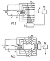
- la figure 2 représente une première forme de réalisation du circuit de détection du dispositif de la fig. 1,
- la figure 3 représente une deuxième forme de réalisation du circuit de détection du dispositif de la fig. 1, et,
- la figure 4 représente une troisième forme de réalisation du circuit de détection du dispositif de la figure 1.
- FIG. 1 represents an exploded perspective view of the main elements of the device of the invention,
- 2 shows a first embodiment of the detection circuit of the device of FIG. 1,
- FIG. 3 represents a second embodiment of the detection circuit of the device of FIG. 1, and,
- FIG. 4 represents a third embodiment of the detection circuit of the device of FIG. 1.
Un dispositif anti-fraude pour lecteur d'objets portatifs, en l'occurrence un lecteur de cartes à mémoire, est maintenant décrit. Plus précisément, et comme cela a été expliqué, le dispositif de l'invention permet de détecter la présence d'une connexion conductrice entre les contacts reliés aux circuits de traitement du lecteur et le milieu extérieur, connexion qui permet à un fraudeur de leurrer ces circuits, à l'aide d'un ordinateur portable par exemple.An anti-fraud device for a portable object reader, in this case a memory card reader, is now described. More precisely, and as has been explained, the device of the invention makes it possible to detect the presence of a conductive connection between the contacts connected to the processing circuits of the reader and the external environment, connection which allows a fraudster to deceive these circuits, using a laptop for example.
En référence à la figure 1, le dispositif anti-fraude 1 comprend un boîtier 10, ici métallique, dont le volume intérieur est cloisonné en trois cavités 11, 14 et 15.With reference to FIG. 1, the anti-fraud device 1 comprises a
Le boîtier 10 comprend, du côté dirigé vers l'utilisateur du lecteur, un orifice, en l'occurrence une fente 12, qui permet l'introduction de la carte 2 de l'utilisateur. La fente 12 débouche dans la cavité 11, qui comporte, dans la paroi opposée à celle dans laquelle est pratiquée la fente 12, une fente 13 identique débouchant dans la cavité 15. Dans la cavité 15 est disposé un dispositif de prélèvement 3, pourvu d'une fente d'introduction 32.The
De façon connue, la carte 2 de l'utilisateur comporte un circuit électronique intégré 21 pourvu d'une pluralité de contact d'accès, et destiné à mémoriser au moins des données d'identification. Le dispositif de prélèvement est du type connu qui comprend autant de lames souples qu'il y a de contact d'accès au circuit électronique 21, chaque lame souple formant un contact de prélèvement qui vient coopérer avec un contact d'accès correspondant au circuit 21 lorsque la carte 2 est insérée dans le dispositif de prélèvement 3. Les lames souples ne sont pas visibles sur la figure 1, mais elles sont représentées schématiquement sur les figures 2, 3 et 4 où elles portent la référence 31.In known manner, the card 2 of the user comprises an integrated
Lorsque la carte 2 est introduite à fond dans la fente 12, selon la flèche 6, elle traverse donc la cavité 11, puis la fente 13 et, dans la cavité 15, elle pénètre dans le dispositif de prélèvement 3 par la fente 32. Lorsque l'extrémité de la carte 2 qui porte le circuit 21 vient en butée contre le fond du dispositif de prélèvement 3, les lames souples formant contacts de prélèvement 31 viennent coopérer avec les contacts d'accès au circuit 21.When the card 2 is fully inserted into the
Une cavité 14, contiguë à la cavité 11, est destinée à recevoir un oscillateur haute fréquence 7, dont la fréquence est ici égale à 100 MHz. Le signal de sortie de l'oscillateur 7 est appliqué à une antenne, comprenant une piste conductrice 71 déposée sur un substrat isolant 72. Le substrat isolant 72 est de la taille de la cavité 11 et vient, en fonctionnement normal, la coiffer. La piste conductrice 71 est ici en forme de spirale qui s'étend sur toute la surface du substrat 72.A
Un circuit imprimé 8, relié, de façon non représentée sur la figure 1 dans un souci de simplicité, d'une part à l'oscillateur 7, et d'autre part au dispositif de prélèvement 3, est disposé dans la cavité 15.A printed
Un couvercle 9 ferme le boîtier 10.A cover 9 closes the
Avant de décrire plus en détail les composants et le fonctionnement du circuit 8, le fonctionnement d'ensemble du dispositif qui vient d'être décrit est maintenant abordé.Before describing the components and the operation of the
En fonctionnement normal, l'oscillateur 7 et l'antenne 71 font régner, à l'intérieur de la cavité 11, un champ électromagnétique haute fréquence, ici à 100 MHz. Lorsqu'un fraudeur introduit une carte 2 sur laquelle il a soudé une connexion conductrice 25 reliée par exemple à un ordinateur portable non représenté, cette connexion 25 traverse obligatoirement la cavité 11, du fait que celle-ci est disposée en amont du dispositif de prélèvement 3 sur le trajet d'introduction de la carte 2.In normal operation, the oscillator 7 and the
La connexion 25 forme antenne, capte une partie de l'énergie du champ électromagnétique dans la cavité 11, et il en résulte un signal à 100 MHz sur le contact de prélèvement 31 qui vient coopérer avec le contact d'accès au circuit 21 relié à la connexion 25. Pour détecter la présence de cette connexion 25, il suffit donc de rechercher un signal à 100 MHz parmi les signaux prélevés par les contacts de prélèvement 31. En cas de détection d'un tel signal, on inhibe les circuits de traitement du lecteur, normalement destinés à autoriser, après vérification des données d'identification, une opération tel qu'un retrait d'argent, par exemple. Le cas échéant, on déclenche une alarme.The
Ici, le champ électromagnétique reste confiné à l'intérieur de la cavité 11 malgré les orifices 12 et 13, car ceux-ci sont de dimensions notablement inférieures à la demi-longueur d'onde, et sont pratiqués dans des parois relativement épaisses. Ils se comportent donc, pour le champ électromagnétique, comme des guides d'ondes très en dessous de leur fréquence de coupure basse. Il en résulte que celui-ci ne peut traverser ces orifices 12 et 13 qu'en subissant une forte atténuation. Lorsque l'objet portatif n'est pas une carte, mais une clé ou un objet cylindrique, les conditions ci-dessus restent faciles à respecter, tant que les dimensions de l'objet portatif restent raisonnables.Here, the electromagnetic field remains confined to the interior of the
Sur la figure 1, il est important de faire la différence entre le rôle de la paroi qui sépare les cavités 11 et 15 et le rôle de la paroi qui sépare les cavités 11 et 14. La paroi qui sépare les cavités 11 et 15 a un rôle d'écran électromagnétique destiné à empêcher le champ qui règne dans la cavité 11 de parvenir dans la cavité 15 autrement que par l'intermédiaire de la connexion 25 formant antenne. Par contre, la paroi qui sépare les cavités 11 et 14 a un simple rôle de barrière mécanique, pour protéger l'oscillateur 7 des objets divers susceptibles d'être introduits par l'orifice 12.In FIG. 1, it is important to differentiate between the role of the wall which separates the
Ici, dans le but de simplifier les opérations de détection, le signal de sortie de l'oscillateur 7 est modulé en amplitude par un signal basse fréquence, c'est-à-dire dont la fréquence est ici inférieure à sensiblement 100 kHz.Here, in order to simplify the detection operations, the output signal from the oscillator 7 is amplitude modulated by a low frequency signal, that is to say the frequency here is less than substantially 100 kHz.
En référence maintenant à la figure 2, et dans une première forme de réalisation, le circuit 8 comprend un unique circuit 52 de préamplification et de démodulation pourvu d'une entrée reliée, par l'intermédiaire d'une pluralité de condensateurs 51, à chacun des contacts de prélèvement 31.Referring now to FIG. 2, and in a first embodiment, the
Chacun des contacts de prélèvement 31 est par ailleurs relié au circuit de traitement 4 dont il a été question et qui est destiné, en fonctionnement normal, à vérifier les données mémorisées dans le circuit 21.Each of the
Le circuit 52 est suivi d'un circuit 54 de détection du signal basse fréquence qui a servi à moduler le signal de sortie de l'oscillateur 7. La sortie du circuit 54 est reliée à une entrée d'inhibition du circuit de traitement 4.The
Dans la forme de réalisation de la figure 2, la présence des condensateurs 51, tous reliés à l'entrée du circuit 52, peut cependant introduire un couplage entre les signaux prélevés, préjudiciable au bon fonctionnement du circuit de traitement 4, même en l'absence de connexion 25.In the embodiment of FIG. 2, the presence of the capacitors 51, all connected to the input of the
La forme de réalisation de la figure 3 ne souffre pas de cet inconvénient. A cet effet, elle comprend autant de circuit 52 qu'il y a de contacts de prélèvement 31, l'entrée de chaque circuit 52 étant reliée à un contact de prélèvement 31 correspondant, et sa sortie étant reliée à une des entrées d'un circuit de sommation 53, suivi du circuit 54 déjà décrit, lui-même relié au circuit 4 non représenté dans un souci de simplicité. Dans ce cas, il n'y a aucun couplage parasite entre les contacts de prélèvement et le circuit 4 fonctionne comme en l'absence de dispositif anti-fraude.The embodiment of Figure 3 does not suffer from this drawback. To this end, it comprises as
Dans la forme de réalisation de la figure 4, le dispositif de prélèvement 3 comprend une boucle 55 formant antenne, disposée au voisinage du circuit 21 lorsque la carte 2 est introduite dans le lecteur. Dans ce cas, il n'y a pas de contact entre la boucle 55 et les contacts de prélèvement 31. La boucle 55 est suivie des circuits 52 et 54 comme dans le cas de la figure 1.In the embodiment of FIG. 4, the sampling device 3 comprises a
Naturellement, la portée de la présente demande n'est pas limitée à la forme de réalisation qui vient d'être décrite. C'est ainsi que si la modulation du champ électromagnétique dans la cavité 11 facilite la détection ultérieure du signal ramené par la connexion 25, ceci n'est pas obligatoire, et on pourrait également utiliser un champ haute fréquence non modulé, en détectant directement le signal à la fréquence du champ, éventuellement après une amplification haute fréquence.Naturally, the scope of the present application is not limited to the embodiment which has just been described. Thus, if the modulation of the electromagnetic field in the
Comme cela a déjà été signalé, il serait possible de faire varier la fréquence du signal de sortie de l'oscillateur 7, à la manière de celle d'un wobulateur, pour déjouer toute tentative d'absorption du signal capté par la connexion 25 à l'aide d'un circuit bouchon accordé, par exemple.As already mentioned, it would be possible to vary the frequency of the output signal of the oscillator 7, like that of a wobulator, to thwart any attempt to absorb the signal received by the
Il serait possible d'utiliser d'autres types d'antenne que l'antenne inductive 71, et notamment une antenne capacitive.It would be possible to use other types of antenna than the
Il est à noter qu'il n'est pas nécessaire que la connexion 25 soit métallique pour être détectée. C'est ainsi que, même si elle est réalisée en carbone, ou à l'aide d'une peinture conductrice, le dispositif anti-fraude de l'invention reste efficace.Note that
Claims (8)
Applications Claiming Priority (2)
| Application Number | Priority Date | Filing Date | Title |
|---|---|---|---|
| FR909005258A FR2661531B1 (en) | 1990-04-25 | 1990-04-25 | ANTI-FRAUD DEVICE FOR READER OF PORTABLE OBJECTS PROVIDED EACH OF AN ELECTRONIC MEMORY CIRCUIT. |
| FR9005258 | 1990-04-25 |
Publications (1)
| Publication Number | Publication Date |
|---|---|
| EP0454570A1 true EP0454570A1 (en) | 1991-10-30 |
Family
ID=9396065
Family Applications (1)
| Application Number | Title | Priority Date | Filing Date |
|---|---|---|---|
| EP91401079A Withdrawn EP0454570A1 (en) | 1990-04-25 | 1991-04-23 | Anti-fraud device for portable object reader comprising an electronic memory-circuit |
Country Status (2)
| Country | Link |
|---|---|
| EP (1) | EP0454570A1 (en) |
| FR (1) | FR2661531B1 (en) |
Cited By (3)
| Publication number | Priority date | Publication date | Assignee | Title |
|---|---|---|---|---|
| US5412318A (en) * | 1992-03-17 | 1995-05-02 | Landis & Gyr Business Support Ag | Device for detecting attempts at fraud on an apparatus for reading and writing on a chip card |
| EP0945822A3 (en) * | 1998-03-26 | 2000-06-28 | Ncr International Inc. | Card reader |
| WO2007134418A1 (en) * | 2006-05-24 | 2007-11-29 | Banco Bradesco S.A. | Operation abnormality detector of electronic modules |
Citations (5)
| Publication number | Priority date | Publication date | Assignee | Title |
|---|---|---|---|---|
| EP0022390A1 (en) * | 1979-06-26 | 1981-01-14 | Imphy S.A. | Method of marking and identifying objects coded by means of electric conducting elements |
| US4388524A (en) * | 1981-09-16 | 1983-06-14 | Walton Charles A | Electronic identification and recognition system with code changeable reactance |
| FR2554262A1 (en) * | 1983-10-28 | 1985-05-03 | Flonic Sa | Anti-fraud device for electronic-memory card reader |
| EP0183523A2 (en) * | 1984-11-26 | 1986-06-04 | Toyota Jidosha Kabushiki Kaisha | Automobile antenna system |
| FR2646260A1 (en) * | 1989-04-19 | 1990-10-26 | Dassault Electronique | ADVANCED MICROCIRCUIT CARD READER |
-
1990
- 1990-04-25 FR FR909005258A patent/FR2661531B1/en not_active Expired - Lifetime
-
1991
- 1991-04-23 EP EP91401079A patent/EP0454570A1/en not_active Withdrawn
Patent Citations (5)
| Publication number | Priority date | Publication date | Assignee | Title |
|---|---|---|---|---|
| EP0022390A1 (en) * | 1979-06-26 | 1981-01-14 | Imphy S.A. | Method of marking and identifying objects coded by means of electric conducting elements |
| US4388524A (en) * | 1981-09-16 | 1983-06-14 | Walton Charles A | Electronic identification and recognition system with code changeable reactance |
| FR2554262A1 (en) * | 1983-10-28 | 1985-05-03 | Flonic Sa | Anti-fraud device for electronic-memory card reader |
| EP0183523A2 (en) * | 1984-11-26 | 1986-06-04 | Toyota Jidosha Kabushiki Kaisha | Automobile antenna system |
| FR2646260A1 (en) * | 1989-04-19 | 1990-10-26 | Dassault Electronique | ADVANCED MICROCIRCUIT CARD READER |
Cited By (6)
| Publication number | Priority date | Publication date | Assignee | Title |
|---|---|---|---|---|
| US5412318A (en) * | 1992-03-17 | 1995-05-02 | Landis & Gyr Business Support Ag | Device for detecting attempts at fraud on an apparatus for reading and writing on a chip card |
| US5510720A (en) * | 1992-03-17 | 1996-04-23 | Landis & Gyr Business Support Ag | Device for detecting attempts at fraud on an apparatus for reading and writing on a chip card |
| EP0945822A3 (en) * | 1998-03-26 | 2000-06-28 | Ncr International Inc. | Card reader |
| US6196463B1 (en) | 1998-03-26 | 2001-03-06 | Ncr Corporation | Card reader |
| WO2007134418A1 (en) * | 2006-05-24 | 2007-11-29 | Banco Bradesco S.A. | Operation abnormality detector of electronic modules |
| US7965194B2 (en) | 2006-05-24 | 2011-06-21 | Banco Bradesco S.A. | Operation abnormality detector of electronic modules, particularly a card reader in a self-serving bank machine |
Also Published As
| Publication number | Publication date |
|---|---|
| FR2661531A1 (en) | 1991-10-31 |
| FR2661531B1 (en) | 1994-09-30 |
Similar Documents
| Publication | Publication Date | Title |
|---|---|---|
| EP1918859B1 (en) | Device for protection against fraud in contactless communication objects | |
| EP0374018B1 (en) | Device for the remote exchange of information between a portable object and a station | |
| FR2914518A1 (en) | SECURE COMMUNICATION SYSTEM BETWEEN A CONTACTLESS CARD READER AND A CARD. | |
| EP1794918B1 (en) | Secure contactless communication device and method | |
| FR2964778A1 (en) | DEVICE FOR PROTECTING A CONNECTOR AND A COMMUNICATION WIRE OF A MEMORY CARD READER. | |
| FR2554262A1 (en) | Anti-fraud device for electronic-memory card reader | |
| CA2657699A1 (en) | Radiofrequency identification device (rfid) affixed to an object to be identified | |
| CA3003618C (en) | Memory card reader body with a protective mesh on both sides | |
| EP0454570A1 (en) | Anti-fraud device for portable object reader comprising an electronic memory-circuit | |
| EP0177394B1 (en) | Ultrasonic surveillance system for container seals using independent terminals | |
| EP1087332B1 (en) | Transponder constructed for several different applications | |
| EP1904960B1 (en) | Device for providing active security to a contact-free electronic device | |
| FR2797072A1 (en) | Circuit for detecting the presence or absence of a proximity integrated circuit card | |
| FR2929739A1 (en) | ELECTRONIC PAYMENT TERMINAL FOR AUTOMAT | |
| EP0468848B1 (en) | Electrical connector for chip card and device and method for fraud detection making use of it | |
| EP1309938B1 (en) | Antenna generating an electromagnetic field for transponder | |
| WO2019186002A1 (en) | Device for detecting, by induction, intention of locking or unlocking an opening element of a motor vehicle with primary and secondary coils | |
| EP2790124B1 (en) | Secured connector | |
| FR2646261A1 (en) | Anti-fraud device for electronic memory card reader | |
| EP2378453B1 (en) | Portable electronic payment terminal suitable for running non-certified programs | |
| WO2021204658A1 (en) | Electronic payment device with means for blocking access to a data storage module | |
| EP0197810A1 (en) | Method and device for recognizing an individual | |
| EP3987431B1 (en) | Hybrid transaction card reading system | |
| EP0798658A1 (en) | Device for information transfer between a portable object and a reader | |
| CA2414353C (en) | Reading and collecting device for contact-free readable media |
Legal Events
| Date | Code | Title | Description |
|---|---|---|---|
| PUAI | Public reference made under article 153(3) epc to a published international application that has entered the european phase |
Free format text: ORIGINAL CODE: 0009012 |
|
| AK | Designated contracting states |
Kind code of ref document: A1 Designated state(s): CH DE LI |
|
| STAA | Information on the status of an ep patent application or granted ep patent |
Free format text: STATUS: THE APPLICATION IS DEEMED TO BE WITHDRAWN |
|
| 18D | Application deemed to be withdrawn |
Effective date: 19920504 |