EP0454893B1 - Manipulateur porte-appareil d'examen pour cuve de pression des réacteurs nucléaires - Google Patents
Manipulateur porte-appareil d'examen pour cuve de pression des réacteurs nucléaires Download PDFInfo
- Publication number
- EP0454893B1 EP0454893B1 EP90113438A EP90113438A EP0454893B1 EP 0454893 B1 EP0454893 B1 EP 0454893B1 EP 90113438 A EP90113438 A EP 90113438A EP 90113438 A EP90113438 A EP 90113438A EP 0454893 B1 EP0454893 B1 EP 0454893B1
- Authority
- EP
- European Patent Office
- Prior art keywords
- pressure vessel
- mast
- carrier
- belt
- deflectable
- Prior art date
- Legal status (The legal status is an assumption and is not a legal conclusion. Google has not performed a legal analysis and makes no representation as to the accuracy of the status listed.)
- Expired - Lifetime
Links
Images



Classifications
-
- G—PHYSICS
- G21—NUCLEAR PHYSICS; NUCLEAR ENGINEERING
- G21C—NUCLEAR REACTORS
- G21C17/00—Monitoring; Testing ; Maintaining
- G21C17/003—Remote inspection of vessels, e.g. pressure vessels
- G21C17/01—Inspection of the inner surfaces of vessels
-
- G—PHYSICS
- G01—MEASURING; TESTING
- G01N—INVESTIGATING OR ANALYSING MATERIALS BY DETERMINING THEIR CHEMICAL OR PHYSICAL PROPERTIES
- G01N2291/00—Indexing codes associated with group G01N29/00
- G01N2291/04—Wave modes and trajectories
- G01N2291/044—Internal reflections (echoes), e.g. on walls or defects
-
- G—PHYSICS
- G01—MEASURING; TESTING
- G01N—INVESTIGATING OR ANALYSING MATERIALS BY DETERMINING THEIR CHEMICAL OR PHYSICAL PROPERTIES
- G01N2291/00—Indexing codes associated with group G01N29/00
- G01N2291/26—Scanned objects
- G01N2291/269—Various geometry objects
- G01N2291/2695—Bottles, containers
-
- Y—GENERAL TAGGING OF NEW TECHNOLOGICAL DEVELOPMENTS; GENERAL TAGGING OF CROSS-SECTIONAL TECHNOLOGIES SPANNING OVER SEVERAL SECTIONS OF THE IPC; TECHNICAL SUBJECTS COVERED BY FORMER USPC CROSS-REFERENCE ART COLLECTIONS [XRACs] AND DIGESTS
- Y02—TECHNOLOGIES OR APPLICATIONS FOR MITIGATION OR ADAPTATION AGAINST CLIMATE CHANGE
- Y02E—REDUCTION OF GREENHOUSE GAS [GHG] EMISSIONS, RELATED TO ENERGY GENERATION, TRANSMISSION OR DISTRIBUTION
- Y02E30/00—Energy generation of nuclear origin
- Y02E30/30—Nuclear fission reactors
Definitions
- the invention relates to a device for the non-destructive testing of an upright cylindrical nuclear reactor pressure vessel in which there is a coaxial nuclear fuel tank which is also cylindrical.
- the device has a vertical mast protruding into the pressure vessel, which is movably supported at its upper and lower ends in the circumferential direction of the pressure vessel and which has a carrier for testing devices which can be moved along the mast.
- Devices of this type are described, for example, in German Offenlegungsschrift DE-A-26 44 261.
- the pressure vessels of nuclear reactors are known to be composed of a plurality of curved plate-shaped or preferably ring-shaped parts, the parts being connected to one another by welds.
- the weld seams as well as the parts of the plates directly adjacent to the seams represent critical areas in the pressure vessel, since they can have zones of lower strength as a result of inclusions, cavities, embrittlement and other imperfections. For this reason, it is essential to check the entire pressure vessel, in particular, however, the zones mentioned, before the first start-up and also during operation of the pressure vessel, to ensure that they are free of defects. This is usually done with the aid of ultrasound devices, and inclusions and cavities can be identified and localized as a result of their echo behavior, which differs from the rest of the material.
- a test manipulator which essentially consists of a vertically arranged mast which is movably mounted on running rails at the upper and lower ends.
- the rails are arranged in a ring around the cylindrical nuclear fuel container, so that the mast can be moved with good guidance up and down in the circumferential direction.
- a carrier for the test equipment is mounted on the mast, which carrier can be moved in the vertical direction.
- the entire device is arranged in the space between the nuclear fuel tank and the inner jacket of the pressure tank and is relatively simple.
- Test manipulators of this type can only be used if it concerns reactor constructions in whose annular space between the nuclear fuel tank and the inner jacket of the pressure tank there are no interfering installations, such as pipes or other fittings. This is often the case with newer reactor designs; However, there are numerous older designs which do not meet this condition, so that manipulators of this type cannot be used in such cases.
- the invention has for its object to further develop the known test manipulators for pressure core reactors, so that they can also be used in those reactors in which the test device has to be guided in relatively narrow gaps, with obstacles being formed by internals and other constrictions in the pressure vessel be circumvented.
- the vertical mast does not extend into the narrow annular gap between the nuclear fuel tank and the inner jacket of the pressure tank, but is moved in the space above the nuclear fuel tank, the upper ring rail being interchangeably arranged on the reactor and only being used when a test is being carried out to be carried out.
- the narrow annular space in the area between the nuclear fuel tank and the pressure vessel inner jacket, which can possibly be narrowed by internals, pipes and fittings, is achieved by the deflectable band, which can be guided sensitively in the circumferential direction, in the vertical direction, but also in the radial direction.
- the upper guide of the vertical mast runs on a bridge.
- This bridge is driven by a reversible drive electric motor, which is operatively connected to a ring gear of the upper ring rail.
- the group or also a part connected to it also acts via coupling links on a chassis at the lower end of the mast. In this way, an exact double control can be carried out, which improves the guiding precision of the overall device.
- the coupling links can in principle be mechanical; in today's state of the art, however, electronic coupling elements are preferred; For example, those that scan an incremental scale that is located in the area of the upper ring rail and that transmits the digital dimension obtained in this way to a corresponding control device on the lower rail.
- the deflectable band arranged in the interior of the vertical rail and emerging at the bottom is preferably a link chain, as is known per se, for example from GB-A 2 159 227.
- a link chain instead of a link chain, however, other flexible materials can also be used, for example a correspondingly dimensioned metal band , for example made of stainless steel or a woven or braided band. Is essential only that the band is deformable in the direction perpendicular to its width dimension, that is to say deflectable, and that it is as little deformable as possible in the direction of the width dimension, that is to say it is dimensionally stable.
- the already mentioned first carrier which is located at the end of the deflectable band, can be extended laterally.
- This arrangement opens up the possibility that the carrier together with the test device arranged thereon can be brought into gaps which are not accessible to the deflectable band as such, since there are internals and obstacles in between.
- the belt is then lowered next to these internals and the support at the end of the band can then be guided into gaps behind the internals due to the lateral extension.
- the first carrier is connected to the end of the belt via a two-part telescope, the drawers of which can be driven in a coordinated manner.
- Such a 2-part telescope offers the advantage of great stability even when extended and it offers the possibility of connecting the carrier or the test devices arranged thereon to the power source via ribbon cables.
- the carrier arranged at the end of the deflectable belt have hydraulic recoil nozzles which press it or the test device mounted on it against the inner jacket of the pressure container.
- the mast has a guide opening for the band in the lower area on its side facing the pressure vessel inner jacket and that in the area between this guide opening and the an adjustable boom is arranged with which the belt can be deflected in the direction of the pressure vessel inner surface.
- At least one second support for receiving test devices be arranged on at least one narrow side of the mast, which can be in any direction the longitudinal axis of the mast and on the inner surface of the pressure vessel, laterally to the longitudinal axis of the mast and rotatably about the working axis of the test device.
- This second carrier essentially comes into action when it comes to checking the area above the nuclear fuel container.
- the test areas overlap in a certain area.
- the second carrier When working with the specified manipulator, it may be desirable for the second carrier, together with the test devices arranged thereon, to be removed during operation of the manipulator, e.g. to make changes to the test systems.
- the second carrier including its rotary drive, can be removed by means of a lance.
- the lance can be inserted from above and inserted into a guide funnel. After insertion, it is locked by a quarter or half turn, at the same time the connection between the carrier and the carrier holder is released. The entire unit can then be pulled up with the lance and removed from the top of the reactor vessel.
- the pressure vessel 1 shows an upright cylindrical nuclear reactor pressure vessel 1 in which there is a coaxial nuclear fuel tank 2 which is also cylindrical.
- the pressure vessel 1 has a flange 3 at the upper end, onto which a cover, not shown, is placed during operation, which is fastened with screw bolts 4.
- the pressure vessel 1 has different pipe sockets, which are only indicated at 5.5 'and 5' ', for example. These pipe sockets as well as any other locations on the pressure vessel 1 must be accessible for inspection with the aid of suitable testing devices, usually ultrasound devices.
- a manipulator 8 which has a vertical mast 9.
- the mast is mounted so that it can be moved in the circumferential direction of the pressure vessel at the upper and lower ends, specifically on the upper ring rail 10 and the lower ring rail 11.
- a bridge 12 is initially arranged on the upper ring rail 10 and forms a secant to the upper ring rail 10 and is dimensioned in this way is that the movable mast 9 is reset in the radial direction so far that obstacles such as pipelines arranged in the pressure vessel can be bypassed with a sufficient distance.
- the upper ring rail 10 is detachably attached to the upper edge of the pressure vessel and is placed there only for testing purposes.
- the mast 9 is movably supported at the lower end on a second ring rail 11, which in turn is removably arranged on the upper edge of the nuclear fuel container 2.
- the mast 9 is designed as a hollow rail, in the interior of which there is a band 13 which is displaceable in the longitudinal direction and deflectable in the direction of the container inner jacket. This band emerges in the lower region of the mast 9 and projects into the annular space which is located between the inner lateral surface of the pressure container 1 and the outer lateral surface of the nuclear fuel container 2.
- a first carrier 14 for a test device.
- the bridge 12 has a reversible drive electric motor 15, which is in operative connection with a toothed ring of the upper ring rail 10 and also acts on a chassis at the lower end of the mast 9 via coupling elements (not shown).
- the band 13 is a link chain.
- This chain consists of the individual chain links 16 which are connected to one another by joints 17 arranged between them. The connection must be designed by precise execution so that the chain can be deflected towards the inner jacket of the pressure vessel, but not in the direction perpendicular to it.
- the individual chain links usually have a width of 300-500 mm and a length of about 600 mm.
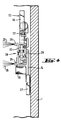
- the first carrier 14, which is located at the lower end of the deflectable band 13, can be extended laterally, which is shown in broken lines in FIG. 1.
- the mast 9 has in the lower area on its side facing the pressure vessel inner jacket a guide opening 18 for the band 13 and in the area between this guide opening and the lower ring rail 11 an adjustable arm 19 with which the band 13 can be deflected in the direction of the pressure vessel inner surface.
- Fig. 1 also reveals that at least one second support 20 for receiving test devices is arranged on at least one narrow side of the mast 9, which is arbitrary in the longitudinal direction of the mast and in the direction of the inner surface of the pressure vessel, laterally to the longitudinal axis of the mast and rotatively around the working axis of the Tester is adjustable.
- This second carrier 20, including its rotary drive, can be removed by means of a lance 21 (FIG. 3).
- Fig. 1 also shows that there are trailing cables 22 and 23, with which the carriers or the test devices arranged thereon are supplied with electrical energy and via which the signals obtained are carried away for evaluation.
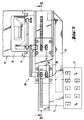
- the carrier 14 has hydraulic recoil nozzles 25, two of which are shown in FIG. 4. If the carrier is brought into the desired position, so the recoil nozzles are switched on and expel water jets 26 towards the rear. This causes the test devices 27 to be pressed against the pressure vessel 1 in the desired manner.
- the carrier 14 can be extended laterally, which should preferably be done via a two-part telescope 28, the two drawers 29 and 30 of which are driven in a coordinated manner and which is connected to the end of the deflectable band 13.
- the carrier 14 is in turn connected to the end of the band via a wide trailing cable 31, via which energy is supplied to the test devices and via which the signals obtained are discharged.
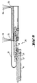
- Wide cables with a plurality of conductor strands arranged next to one another are preferably used as trailing cables, as are known from computer technology. The arrangement is shown in Fig. 5 in the front view and in Fig. 6 in cross section.
- a second support 20 is arranged on at least one narrow side of the mast 9.
- This second support is also used to hold test equipment and can be adjusted as required in the direction of the longitudinal axis of the mast and on the inner surface of the pressure vessel, laterally to the longitudinal axis of the mast and rotatably around the working axis of the test device.
- This second carrier including its rotary drive, should be removable by means of a lance 21 (FIG. 3). Some details of this are shown in FIGS. 7-10.
- the lance 21 is first inserted into an opening provided for this purpose.
- a guide funnel 32 is arranged on the top of the second carrier.
- the lance has a switching nipple 33 at the lower end, which is inserted in the manner shown in FIGS. 7 and 8.
- the carrier is still firmly attached to its anchor. Only when the lance is rotated by 90 ° about its vertical axis is the carrier released from its previous attachment, as is a secure connection to the lance (FIGS. 9 and 10). Once this has been done, the second carrier together with the devices attached to it can be lifted upwards using the lance.
Landscapes
- Physics & Mathematics (AREA)
- Engineering & Computer Science (AREA)
- Plasma & Fusion (AREA)
- General Engineering & Computer Science (AREA)
- High Energy & Nuclear Physics (AREA)
- Monitoring And Testing Of Nuclear Reactors (AREA)
- Investigating Or Analyzing Materials By The Use Of Ultrasonic Waves (AREA)
- Examining Or Testing Airtightness (AREA)
Claims (9)
- Installation pour l'examen non destructif d'une cuve de pression de réacteur nucléaire, cylindrique et en position verticale, dans laquelle se trouve un récipient de combustible nucléaire également cylindrique et agencé coaxialement, avec un mât vertical pénétrant dans la cuve de pression, qui est logé par ses extrémités supérieure et inférieure de façon déplaçable dans la direction périphérique de la cuve de pression et qui présente un porte-appareil d'examen déplaçable le long du mât,
caractérisée en ce que :- le mât (9) est logé par son extrémité supérieure de façon déplaçable sur un pont (12),-- qui, à son tour, est déplaçable sur un premier rail annulaire (10) supérieur, qui est fixé de façon détachable sur le bord supérieur de la cuve de pression;- le mât (9) est logé par son extrémité inférieure de façon déplaçable sur un second rail annulaire (11) inférieur,-- qui, à son tour, est agencé de façon détachable sur le bord supérieur du récipient de combustible nucléaire (2);- le mât (9) est réalisé sous la forme d'un rail creux, à l'intérieur duquel se trouve un ruban (13) déplaçable dans la direction longitudinale, et susceptible d'être défléchi en direction de l'enveloppe intérieure du récipient,
ledit ruban (13) sortant dans la région inférieure du mât (9) hors de celui-ci et qui s'étendant jusqu'à l'espace annulaire entre la surface intérieure de l'enveloppe de la cuve de pression (1) et la surface extérieure de l'enveloppe du récipient de combustible nucléaire (2), et présentant sur son extrémité un premier porte-appareil (14) pour au moins un appareil d'examen. - Installation selon la revendication 1,
caractérisée en ce que
le pont (12) présente un moteur d'entraînement électrique (15) commutable qui se trouve en liaison active avec une couronne dentée du rail annulaire supérieur (10), et qui agit également sur un dispositif de déplacement à l'extrémité inférieure du mât (9) par l'intermédiaire de pièces d'accouplement. - Installation selon l'une ou l'autre des revendications 1 et 2,
caractérisée en ce que le ruban (13) est une chaîne à maillons. - Installation selon l'une quelconque des revendications 1 à 3,
caractérisée en ce que le premier porte-appareil (14) est déplaçable latéralement à l'extrémité du ruban (13) susceptible d'être défléchi. - Installation selon la revendication 4,
caractérisée en ce que le premier porte-appareil (14) est relié à l'extrémité du ruban (13) susceptible d'être défléchi par l'intermédiaire d'un dispositif télescopique en deux parties (28), dont les deux membres (29, 30) sont entraînés en correspondance mutuelle. - Installation selon l'une quelconque des revendications 1 à 5,
caractérisée en ce que
le porte-appareil (14) agencé sur l'extrémité du ruban susceptible d'être défléchi présente des buses de renvoi hydrauliques (25) qui pressent le porte-appareil ou l'appareil d'examen monté sur celui-ci contre l'enveloppe intérieure de la cuve de pression. - Installation selon l'une quelconque des revendications 1 à 6,
caractérisée en ce que
le mât (9) présente dans sa région inférieure et sur son côté orienté vers l'enveloppe intérieure de la cuve de pression une ouverture de guidage (18) pour le ruban (13), et en ce qu'un bras réglable (19) est agencé dans la région entre cette ouverture de guidage et le rail annulaire inférieur (11), bras grâce auquel le ruban (13) est susceptible d'être défléchi en direction de l'enveloppe intérieure de la cuve de pression. - Installation selon l'une quelconque des revendications 1 à 7,
caractérisée en ce que
sur au moins un côté étroit du mât (9) est agencé au moins un second porte-appareil (20) pour la réception d'un appareil d'examen, porte-appareil qui est déplaçable de façon quelconque dans la direction longitudinale du mât, en direction de la surface intérieure de la cuve de pression, en direction latérale de l'axe longitudinal du mât, ainsi qu'en rotation autour de l'axe de fonctionnement de l'appareil d'examen. - Installation selon la revendication 7,
caractérisée en ce que le second porte-appareil (20), y compris son entraînement rotatif, est détachable au moyen d'une lance (21).
Priority Applications (1)
| Application Number | Priority Date | Filing Date | Title |
|---|---|---|---|
| AT9090113438T ATE105647T1 (de) | 1990-05-03 | 1990-07-13 | Yruefgeraete-manipulator fuer druckbehaelter von kernreaktoren. |
Applications Claiming Priority (2)
| Application Number | Priority Date | Filing Date | Title |
|---|---|---|---|
| DE4014161A DE4014161A1 (de) | 1990-05-03 | 1990-05-03 | Pruefgeraete-manipulator fuer druckbehaelter von kernreaktoren |
| DE4014161 | 1990-05-05 |
Publications (2)
| Publication Number | Publication Date |
|---|---|
| EP0454893A1 EP0454893A1 (fr) | 1991-11-06 |
| EP0454893B1 true EP0454893B1 (fr) | 1994-05-11 |
Family
ID=6405618
Family Applications (1)
| Application Number | Title | Priority Date | Filing Date |
|---|---|---|---|
| EP90113438A Expired - Lifetime EP0454893B1 (fr) | 1990-05-03 | 1990-07-13 | Manipulateur porte-appareil d'examen pour cuve de pression des réacteurs nucléaires |
Country Status (6)
| Country | Link |
|---|---|
| US (1) | US5128094A (fr) |
| EP (1) | EP0454893B1 (fr) |
| JP (1) | JPH0687053B2 (fr) |
| AT (1) | ATE105647T1 (fr) |
| DE (2) | DE4014161A1 (fr) |
| ES (1) | ES2054170T3 (fr) |
Families Citing this family (10)
| Publication number | Priority date | Publication date | Assignee | Title |
|---|---|---|---|---|
| DE4237695C3 (de) * | 1992-05-13 | 2000-02-24 | Bbc Reaktor Gmbh | Verfahren und Einrichtung zum zerstörungsfreien Prüfen einer Durchführung eines Reaktordruckbehälter-Deckels |
| SE506031C2 (sv) * | 1993-12-28 | 1997-11-03 | Abb Tekniska Roentgencent | Anordning och förfarande för inspektion av ett reaktorkärl |
| DE4431625C1 (de) * | 1994-09-07 | 1996-03-07 | Siemens Ag | Vorrichtung zur zerstörungsfreien Prüfung des Kernmantels von Siedewasser-Kernreaktoranlagen |
| JP3014766B2 (ja) * | 1994-11-30 | 2000-02-28 | シーメンス アクチエンゲゼルシヤフト | 炉心容器の外壁をそれを包囲する熱遮蔽体の範囲で点検するための装置および方法 |
| JP3553080B2 (ja) * | 1994-11-30 | 2004-08-11 | フラマトム アンプ ゲゼルシャフト ミット ベシュレンクテル ハフツング | 炉心容器の外壁をそれを包囲する熱遮蔽体の範囲で点検するための装置および方法 |
| US5682409A (en) * | 1996-08-16 | 1997-10-28 | General Electric Company | Neutron fluence surveillance capsule holder modification for boiling water reactor |
| DE202004013045U1 (de) * | 2004-08-19 | 2005-09-08 | Cegelec Anlagen- Und Automatisierungstechnik Gmbh & Co. Kg | Ultraschall-Prüfeinrichtung |
| US7587942B2 (en) * | 2006-11-29 | 2009-09-15 | General Electric Company | Ultrasonic inspection crawler and method for inspecting welds of jet pumps in a nuclear reactor vessel |
| US8590383B2 (en) * | 2008-06-24 | 2013-11-26 | Alstom Technology Ltd | Ultrasonic inspection probe carrier system for performing non-destructive testing |
| CN101894592B (zh) * | 2010-06-23 | 2012-07-11 | 中广核检测技术有限公司 | 反应堆压力容器检查机的前端探头机构 |
Family Cites Families (13)
| Publication number | Priority date | Publication date | Assignee | Title |
|---|---|---|---|---|
| FR2326766A1 (fr) * | 1975-10-02 | 1977-04-29 | Commissariat Energie Atomique | Structure interne de cuve de chaudiere nucleaire |
| US4149932A (en) * | 1977-03-25 | 1979-04-17 | Westinghouse Electric Corp. | Emergency disconnect means for the manipulator arm of a nuclear reactor vessel inspection apparatus |
| US4149933A (en) | 1977-03-25 | 1979-04-17 | Westinghouse Electric Corp. | Emergency braking system for nuclear reactor vessel inspection apparatus |
| US4169758A (en) * | 1977-10-26 | 1979-10-02 | The Babcock & Wilcox Company | Nuclear reactor vessel inspection apparatus |
| DE3112201A1 (de) * | 1981-03-27 | 1982-10-14 | Interatom Internationale Atomreaktorbau Gmbh, 5060 Bergisch Gladbach | Verfahren und vorrichtung zur detektion der verbreiterung von fugen in einem reaktorbehaelter |
| JPS57166558A (en) * | 1981-04-08 | 1982-10-14 | Hitachi Ltd | Track for run on surface of nuclear reactor pressure container |
| SE438219B (sv) * | 1981-09-29 | 1985-04-01 | Tekniska Roentgencentralen Ab | Anordning for inspektion av ett reaktorkerl |
| JPS5870159A (ja) * | 1981-10-21 | 1983-04-26 | Hitachi Ltd | 圧力容器用軌道の格納容器内搬入組立方法 |
| JPS6015556A (ja) * | 1983-07-08 | 1985-01-26 | Hitachi Ltd | 容器の監視または検査装置用軌道 |
| GB8412608D0 (en) * | 1984-05-17 | 1984-06-20 | Nat Nuclear Corp Ltd | Scanning device |
| DE3524390A1 (de) * | 1985-07-08 | 1987-01-08 | Kraftwerk Union Ag | Pruefmanipulator |
| JP2604208B2 (ja) * | 1988-01-27 | 1997-04-30 | 富士写真フイルム株式会社 | ハロゲン化銀カラー写真感光材料 |
| JPH0210915A (ja) * | 1988-06-28 | 1990-01-16 | Mitsubishi Electric Corp | パルス状信号の極性統一回路 |
-
1990
- 1990-05-03 DE DE4014161A patent/DE4014161A1/de not_active Withdrawn
- 1990-07-13 EP EP90113438A patent/EP0454893B1/fr not_active Expired - Lifetime
- 1990-07-13 ES ES90113438T patent/ES2054170T3/es not_active Expired - Lifetime
- 1990-07-13 AT AT9090113438T patent/ATE105647T1/de not_active IP Right Cessation
- 1990-07-13 DE DE59005688T patent/DE59005688D1/de not_active Expired - Lifetime
- 1990-09-03 JP JP2230759A patent/JPH0687053B2/ja not_active Expired - Fee Related
-
1991
- 1991-01-08 US US07/638,830 patent/US5128094A/en not_active Expired - Lifetime
Also Published As
| Publication number | Publication date |
|---|---|
| ATE105647T1 (de) | 1994-05-15 |
| DE4014161A1 (de) | 1991-11-07 |
| EP0454893A1 (fr) | 1991-11-06 |
| US5128094A (en) | 1992-07-07 |
| JPH0687053B2 (ja) | 1994-11-02 |
| ES2054170T3 (es) | 1994-08-01 |
| JPH0413964A (ja) | 1992-01-17 |
| DE59005688D1 (de) | 1994-06-16 |
Similar Documents
| Publication | Publication Date | Title |
|---|---|---|
| DE2826106C2 (de) | Anordnung für den Transport einer Positioniervorrichtung im Inneren eines Dampferzeugers | |
| EP0066791B1 (fr) | Dispositif de mise en oeuvre de travaux d'inspection sur un échangeur de chaleur pour réacteur nucléaire et procédé de mise en place du dispositif dans la chambre de l'échangeur de vapeur | |
| DE2440962A1 (de) | Vorrichtung zum ueberpruefen von schwer zugaenglichen wandteilen unter fernbedienung | |
| DE2411005A1 (de) | Wandklettervorrichtung | |
| DE2930407A1 (de) | Geraet zur untersuchung von rohren in einer anlage | |
| EP0454893A1 (fr) | Manipulateur porte-appareil d'examen pour cuve de pression des réacteurs nucléaires | |
| DD297870A5 (de) | Interventionsvorrichtung, insbesondere zur kontrolle, ueberwachung und unterhaltung von waermeaustauschern | |
| EP2433285B1 (fr) | Procédé et dispositif de contrôle d'un cordon de soudure annulaire d'une canalisation principale de fluide de refroidissement raccordée à un réservoir sous pression du réacteur d'une centrale nucléaire | |
| EP0011213B1 (fr) | Dispositif de contrôle des parois d'une cuve sous pression | |
| EP0137077A2 (fr) | Procédé et dispostif de localisation de chemises défectueuses de barreaux combustibles des réacteurs nucléaires refroidis par eau | |
| DE2912658C3 (de) | Längs einer Bauteilwandung, die von ihrer Oberfläche sich nach innen erstreckende Öffnungen in regelmäßiger Anordnung aufweist, schrittweise bewegliche Vorrichtung | |
| EP0856119B1 (fr) | Procede et dispositif pour l'introduction d'un manipulateur du type chariot, autopropulse, a l'interieur d'une conduite | |
| EP0308730B1 (fr) | Dispositif d'inspection et/ou de réparation de tubes débouchant dans une chambre d'un échangeur de chaleur | |
| DE2733862C3 (de) | Manipulator zur Inspektion und gegebenenfalls Reparatur der Rohre von Wärmetauschern, insbesondere von Dampferzeugern für Kernreaktoren | |
| EP0856118A2 (fr) | Manipulateur du type chariot pour le controle ou le traitement de la surface interieure d'une conduite | |
| DE3524390A1 (de) | Pruefmanipulator | |
| DE3881333T2 (de) | Fehlersuchgeraet durch ultraschall zum einfuegen. | |
| DE4017600C2 (de) | Handhabungsgerät für Arbeiten im Stutzenbereich eines Behälters des Primärkreises in einem Kernkraftwerk, insbesondere für zerstörungsfreie Prüfungen | |
| EP0451527A1 (fr) | Manipulateur pour manutentions, notamment pour examens non-destructifs et méthode pour manipuler un appareil | |
| DE3147296A1 (de) | "manipulator zur pruefung von stutzeneinschweissnaehten" | |
| EP0795179B1 (fr) | Procede et dispositif pour inspecter la paroi exterieure de l'enveloppe de coeur d'un reacteur nucleaire dans la zone d'un bouclier thermique qui l'entoure | |
| DE69400335T2 (de) | Vorrichtung zur materialüberprüfung, insbesondere in einem druckwasserreaktor | |
| DE2923094C2 (de) | Isoliervorrichtung | |
| WO1997014910A2 (fr) | Manipulateur interieur pour le controle ou le traitement de la surface interieure d'une conduite | |
| DE2709023A1 (de) | Pruefeinrichtung fuer grossbehaelter |
Legal Events
| Date | Code | Title | Description |
|---|---|---|---|
| PUAI | Public reference made under article 153(3) epc to a published international application that has entered the european phase |
Free format text: ORIGINAL CODE: 0009012 |
|
| AK | Designated contracting states |
Kind code of ref document: A1 Designated state(s): AT BE CH DE DK ES FR GB GR IT LI LU NL SE |
|
| 17P | Request for examination filed |
Effective date: 19911202 |
|
| 17Q | First examination report despatched |
Effective date: 19930914 |
|
| GRAA | (expected) grant |
Free format text: ORIGINAL CODE: 0009210 |
|
| AK | Designated contracting states |
Kind code of ref document: B1 Designated state(s): AT BE CH DE DK ES FR GB GR IT LI LU NL SE |
|
| PG25 | Lapsed in a contracting state [announced via postgrant information from national office to epo] |
Ref country code: IT Free format text: LAPSE BECAUSE OF FAILURE TO SUBMIT A TRANSLATION OF THE DESCRIPTION OR TO PAY THE FEE WITHIN THE PRESCRIBED TIME-LIMIT;WARNING: LAPSES OF ITALIAN PATENTS WITH EFFECTIVE DATE BEFORE 2007 MAY HAVE OCCURRED AT ANY TIME BEFORE 2007. THE CORRECT EFFECTIVE DATE MAY BE DIFFERENT FROM THE ONE RECORDED. Effective date: 19940511 Ref country code: GB Effective date: 19940511 Ref country code: GR Free format text: LAPSE BECAUSE OF FAILURE TO SUBMIT A TRANSLATION OF THE DESCRIPTION OR TO PAY THE FEE WITHIN THE PRESCRIBED TIME-LIMIT Effective date: 19940511 Ref country code: DK Effective date: 19940511 Ref country code: BE Effective date: 19940511 Ref country code: FR Effective date: 19940511 |
|
| REF | Corresponds to: |
Ref document number: 105647 Country of ref document: AT Date of ref document: 19940515 Kind code of ref document: T |
|
| REF | Corresponds to: |
Ref document number: 59005688 Country of ref document: DE Date of ref document: 19940616 |
|
| PG25 | Lapsed in a contracting state [announced via postgrant information from national office to epo] |
Ref country code: AT Effective date: 19940713 |
|
| PG25 | Lapsed in a contracting state [announced via postgrant information from national office to epo] |
Ref country code: LU Free format text: LAPSE BECAUSE OF NON-PAYMENT OF DUE FEES Effective date: 19940731 |
|
| EN | Fr: translation not filed | ||
| GBV | Gb: ep patent (uk) treated as always having been void in accordance with gb section 77(7)/1977 [no translation filed] |
Effective date: 19940511 |
|
| EAL | Se: european patent in force in sweden |
Ref document number: 90113438.7 |
|
| PLBE | No opposition filed within time limit |
Free format text: ORIGINAL CODE: 0009261 |
|
| STAA | Information on the status of an ep patent application or granted ep patent |
Free format text: STATUS: NO OPPOSITION FILED WITHIN TIME LIMIT |
|
| 26N | No opposition filed | ||
| REG | Reference to a national code |
Ref country code: CH Ref legal event code: PFA Free format text: MAN ENERGIE GMBH TRANSFER- GEC ALSTHOM ENERGIE GMBH |
|
| NLT1 | Nl: modifications of names registered in virtue of documents presented to the patent office pursuant to art. 16 a, paragraph 1 |
Owner name: GEC ALSTHOM ENERGIE GMBH |
|
| REG | Reference to a national code |
Ref country code: ES Ref legal event code: PC2A Owner name: GEC ALSTHOM ENERGIE GMBH |
|
| REG | Reference to a national code |
Ref country code: CH Ref legal event code: PFA Free format text: GEC ALSTHOM ENERGIE GMBH TRANSFER- ALSTOM ENERGIE GMBH |
|
| NLT1 | Nl: modifications of names registered in virtue of documents presented to the patent office pursuant to art. 16 a, paragraph 1 |
Owner name: ALSTOM ENERGIE GMBH |
|
| REG | Reference to a national code |
Ref country code: ES Ref legal event code: PC2A |
|
| PGFP | Annual fee paid to national office [announced via postgrant information from national office to epo] |
Ref country code: NL Payment date: 20020717 Year of fee payment: 13 |
|
| PG25 | Lapsed in a contracting state [announced via postgrant information from national office to epo] |
Ref country code: NL Free format text: LAPSE BECAUSE OF NON-PAYMENT OF DUE FEES Effective date: 20040201 |
|
| NLV4 | Nl: lapsed or anulled due to non-payment of the annual fee |
Effective date: 20040201 |
|
| PGFP | Annual fee paid to national office [announced via postgrant information from national office to epo] |
Ref country code: ES Payment date: 20070725 Year of fee payment: 18 |
|
| REG | Reference to a national code |
Ref country code: CH Ref legal event code: PFA Owner name: ALSTOM ENERGIE GMBH Free format text: ALSTOM ENERGIE GMBH#FRANKENSTRASSE 150#90461 NUERNBERG (DE) -TRANSFER TO- ALSTOM ENERGIE GMBH#FRANKENSTRASSE 150#90461 NUERNBERG (DE) |
|
| PGFP | Annual fee paid to national office [announced via postgrant information from national office to epo] |
Ref country code: CH Payment date: 20070724 Year of fee payment: 18 |
|
| REG | Reference to a national code |
Ref country code: CH Ref legal event code: PL |
|
| PG25 | Lapsed in a contracting state [announced via postgrant information from national office to epo] |
Ref country code: LI Free format text: LAPSE BECAUSE OF NON-PAYMENT OF DUE FEES Effective date: 20080731 Ref country code: CH Free format text: LAPSE BECAUSE OF NON-PAYMENT OF DUE FEES Effective date: 20080731 |
|
| REG | Reference to a national code |
Ref country code: ES Ref legal event code: FD2A Effective date: 20080714 |
|
| PG25 | Lapsed in a contracting state [announced via postgrant information from national office to epo] |
Ref country code: ES Free format text: LAPSE BECAUSE OF NON-PAYMENT OF DUE FEES Effective date: 20080714 |
|
| PGFP | Annual fee paid to national office [announced via postgrant information from national office to epo] |
Ref country code: SE Payment date: 20090727 Year of fee payment: 20 Ref country code: DE Payment date: 20090810 Year of fee payment: 20 |
|
| EUG | Se: european patent has lapsed | ||
| PG25 | Lapsed in a contracting state [announced via postgrant information from national office to epo] |
Ref country code: DE Free format text: LAPSE BECAUSE OF EXPIRATION OF PROTECTION Effective date: 20100713 |