EP0454951A1 - Moyen d'entraînement pour un cylindre - Google Patents
Moyen d'entraînement pour un cylindre Download PDFInfo
- Publication number
- EP0454951A1 EP0454951A1 EP91101735A EP91101735A EP0454951A1 EP 0454951 A1 EP0454951 A1 EP 0454951A1 EP 91101735 A EP91101735 A EP 91101735A EP 91101735 A EP91101735 A EP 91101735A EP 0454951 A1 EP0454951 A1 EP 0454951A1
- Authority
- EP
- European Patent Office
- Prior art keywords
- hollow roller
- roller
- crosshead
- drive housing
- drive
- Prior art date
- Legal status (The legal status is an assumption and is not a legal conclusion. Google has not performed a legal analysis and makes no representation as to the accuracy of the status listed.)
- Granted
Links
- 230000000149 penetrating effect Effects 0.000 claims 1
- 230000005540 biological transmission Effects 0.000 description 2
- 238000010276 construction Methods 0.000 description 2
- 230000000694 effects Effects 0.000 description 2
- 238000007789 sealing Methods 0.000 description 2
- 238000005452 bending Methods 0.000 description 1
- 230000006735 deficit Effects 0.000 description 1
- 230000001419 dependent effect Effects 0.000 description 1
- 238000006073 displacement reaction Methods 0.000 description 1
- 239000012530 fluid Substances 0.000 description 1
- 230000001771 impaired effect Effects 0.000 description 1
- 239000007788 liquid Substances 0.000 description 1
- 238000005096 rolling process Methods 0.000 description 1
Images
Classifications
-
- B—PERFORMING OPERATIONS; TRANSPORTING
- B21—MECHANICAL METAL-WORKING WITHOUT ESSENTIALLY REMOVING MATERIAL; PUNCHING METAL
- B21B—ROLLING OF METAL
- B21B27/00—Rolls, roll alloys or roll fabrication; Lubricating, cooling or heating rolls while in use
- B21B27/02—Shape or construction of rolls
- B21B27/03—Sleeved rolls
- B21B27/05—Sleeved rolls with deflectable sleeves
- B21B27/055—Sleeved rolls with deflectable sleeves with sleeves radially deflectable on a stationary beam by means of hydraulic supports
-
- B—PERFORMING OPERATIONS; TRANSPORTING
- B21—MECHANICAL METAL-WORKING WITHOUT ESSENTIALLY REMOVING MATERIAL; PUNCHING METAL
- B21B—ROLLING OF METAL
- B21B35/00—Drives for metal-rolling mills, e.g. hydraulic drives
- B21B35/12—Toothed-wheel gearings specially adapted for metal-rolling mills; Housings or mountings therefor
-
- D—TEXTILES; PAPER
- D21—PAPER-MAKING; PRODUCTION OF CELLULOSE
- D21G—CALENDERS; ACCESSORIES FOR PAPER-MAKING MACHINES
- D21G1/00—Calenders; Smoothing apparatus
- D21G1/0006—Driving arrangements
-
- F—MECHANICAL ENGINEERING; LIGHTING; HEATING; WEAPONS; BLASTING
- F16—ENGINEERING ELEMENTS AND UNITS; GENERAL MEASURES FOR PRODUCING AND MAINTAINING EFFECTIVE FUNCTIONING OF MACHINES OR INSTALLATIONS; THERMAL INSULATION IN GENERAL
- F16C—SHAFTS; FLEXIBLE SHAFTS; ELEMENTS OR CRANKSHAFT MECHANISMS; ROTARY BODIES OTHER THAN GEARING ELEMENTS; BEARINGS
- F16C13/00—Rolls, drums, discs, or the like; Bearings or mountings therefor
- F16C13/02—Bearings
- F16C13/022—Bearings supporting a hollow roll mantle rotating with respect to a yoke or axle
- F16C13/024—Bearings supporting a hollow roll mantle rotating with respect to a yoke or axle adjustable for positioning, e.g. radial movable bearings for controlling the deflection along the length of the roll mantle
- F16C13/026—Bearings supporting a hollow roll mantle rotating with respect to a yoke or axle adjustable for positioning, e.g. radial movable bearings for controlling the deflection along the length of the roll mantle by fluid pressure
- F16C13/028—Bearings supporting a hollow roll mantle rotating with respect to a yoke or axle adjustable for positioning, e.g. radial movable bearings for controlling the deflection along the length of the roll mantle by fluid pressure with a plurality of supports along the length of the roll mantle, e.g. hydraulic jacks
-
- F—MECHANICAL ENGINEERING; LIGHTING; HEATING; WEAPONS; BLASTING
- F26—DRYING
- F26B—DRYING SOLID MATERIALS OR OBJECTS BY REMOVING LIQUID THEREFROM
- F26B13/00—Machines and apparatus for drying fabrics, fibres, yarns, or other materials in long lengths, with progressive movement
- F26B13/10—Arrangements for feeding, heating or supporting materials; Controlling movement, tension or position of materials
- F26B13/14—Rollers, drums, cylinders; Arrangement of drives, supports, bearings, cleaning
Definitions
- the invention relates to a drive arrangement for a roller, which consists of a rotating hollow roller, a crosshead passing through it and a hydraulic support device, which is supported on the crosshead and acts against the inner circumference of the hollow roller, and which acts on the crosshead to act on the bending of the hollow roller transmits which can bend within the hollow roller and in this way applies the opposing forces.
- the hydraulic support device can consist of individual piston-like support elements attached to the crosshead on the side of the roll gap or a continuous support strip which is under the effect of a liquid pressure along its entire length.
- the space between the crosshead and the inner circumference of the hollow roller is divided by longitudinal seals and end transverse seals into semi-cylindrical shell-shaped longitudinal chambers, of which one longitudinal chamber on the side of the roll gap can be filled with hydraulic fluid which exerts a uniform pressure on the inner circumference of the hollow roller.
- rollers in question there are, in addition to the differences in the support device, also differences in the guidance of the hollow roller at the ends on the crosshead.
- the hollow roller is supported at the ends on the crosshead via roller bearings.
- a guide ring surrounding the crosshead is provided at the ends, which is guided linearly on the crosshead in the active plane perpendicular to the axis of the roller and on which the hollow roller in turn a rolling bearing is mounted.
- this roller bearing has only pure management tasks perpendicular to the working plane and cannot transmit forces in the working plane because the guide ring is freely movable in the working plane perpendicular to the roll axis.
- the hollow roller can be displaced by several 10 mm in relation to the crosshead in such rollers.
- the opening and delivery of the roll gap can be effected by the support device and the crosshead can be fixedly mounted in the roll stand, which means a great design simplification compared to other embodiments in which the crosshead had to be moved on rockers or in slide guides in the active plane to open or close the nip.
- a solution to this problem is that the housing in which the drive pinion is mounted is in turn mounted on the hollow roller, so that the Drive pinion and the drive toothing on the hollow roller take an invariable position against each other and a perfect power transmission is ensured.
- the drive pinion is in turn connected to the outer drive motor via a cardan shaft.
- An embodiment of this type is the subject of DE-OS 25 o7 677.
- the drive housing is mounted on the outside of an axial extension thereof connected to the hollow roller.
- the end of the crosshead extends through the shoulder and thus also through the drive housing and is supported outside of it in a self-aligning bearing in a roller stand or the like.
- a guide ring is guided linearly displaceably in the active plane perpendicular to the roller axis on the end of the crosshead and is mounted on its outside on the inner circumference of the approach.
- the invention has for its object to avoid such influences on the line force.
- the gear housing is no longer supported on the outside of the neck of the hollow roller, but rather on the inside thereof, the drive housing being supported on the axial neck of the drive housing engaging in the neck of the hollow roller via a bearing arranged therebetween.
- the effect of this construction is that the end of the crosshead is no longer the rapidly rotating approach of the hollow roller, but only the fixed approach of the gear housing, which can form a non-rotating point of attack for the guide ring. This means that the driver no longer experiences a moment of drag.
- the roller according to DE-OS 35 32 843 also has a drive housing with an axial shoulder on which a toothed drive ring is mounted on the outside, which is rotatably connected to the hollow roller. There is also an inner stroke and a guide ring, but the latter is offset axially inwards into the hollow roller relative to the bearing on the shoulder of the drive housing.
- a torque arm is provided on the crosshead, on which the guide ring is supported against the driving torque. The impairment of the smooth running of the straight guide on the guide ring is also given here.
- the mounting of the hollow roller on the guide ring and the mounting of the drive housing on the hollow roller are integrated to a certain extent on the shoulder of the drive housing. Because the guide ring on one side only faces the non-rotating extension of the gear housing, a pivot bearing arrangement can be saved here, which is an important cost factor in view of the size of such bearings.
- the guide ring is expediently rotationally connected to the axial extension of the drive housing via a self-aligning bearing.
- connection to the axial extension of the drive housing can be established and, at the same time, a possibility can be created for compensating the deflection of the crosshead relative to the hollow roller.
- the arrangement according to claim 4 serves for optimal power transmission, while the arrangement according to claim 5 ensures optimal use of space in the axial direction.
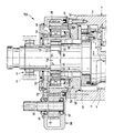
- the roller designated 100 in the drawing as a whole comprises a rotating hollow roller 1, which forms the working roller circumference 2 and has a cylindrical inner circumference 4.
- the hollow roller 1 is penetrated lengthwise by an non-rotatable crosshead 3, which protrudes with its end 3 ′ from the hollow roller and is mounted in a roller stand 6 via a self-aligning bearing 5.
- the crosshead 3 leaves all around distance from the inner circumference 4 of the hollow roller 1 and can thus bend within the hollow roller 1 without coming into contact with the inner circumference 4.
- a hydraulic support device is provided on the upper side of the crosshead 3 facing the roll gap 10 in the drawing, which in the exemplary embodiment consists of piston-like support elements 7 lined up along the crosshead 3, which engage in radial cylinder chambers 8 of the crosshead 3 and with their contact surface 9 bear against the inner circumference 4 of the hollow roller 1.
- the support elements 7 allow a hydraulic force to be exerted against the inner circumference 4 and support the hollow roller 1 from the inside, in the opposite direction, against the line force in the roll gap 10 on the crosshead 3 which deflects under the action of these forces.
- the intermediate space 11 between the crosshead 3 and the inner circumference 4 of the hollow roller 1 is sealed against the accumulating pressure oil emerging at the support elements 7 by means of a mechanical seal arrangement designated as a whole as 12 in the axial direction.
- an axial shoulder 2o which in the exemplary embodiment is composed of two rings 2o 'and 2o''.
- the ring 20 ' is fastened by means of screws 13 directly to the end face of the hollow roller 1 and, with its end face 14 facing inside the hollow roller 1, interacts with the mechanical seal 12.
- the ring 2o '' sits on the outside of the ring 2o 'and is connected to it via screws 15. It has on its outside an external toothing 16 with which a drive pinion 17 cooperates, the pinion shaft 18 is parallel to the axis of the hollow roller 1.
- the pinion 17 is mounted in roller bearings 19 in a drive housing 25 which surrounds the projecting end 3 'of the crosshead 3 and which has an inner axial projection 30 in the form of a sleeve which is attached by means of screws 21 to the wall 22 remote from the hollow roller 1 and perpendicular to the axis of the drive housing 25 is attached.
- the approach 3o extends from the wall 22 against the hollow roller 1 and leaves an inner distance from the outer periphery of the projecting end 3 'of the crosshead 3 and the outer distance from the inner periphery of the axial extension 2o of the hollow roller 1. In the latter spacing space are adjacent to each other with axial Spaced a spherical roller bearing 23 and a radial roller bearing 24, via which the drive housing 25 is rotatably mounted on the inside of the neck 20.
- the drive housing 25 has a torque support, not shown, which acts on an external fixed point and intercepts the torque exerted on the drive housing 25 by the pinion 17 acting on the external toothing 16 of the hollow roller 1.
- a guide ring 4o is provided, the inner opening of which is not circular with respect to the ring axis, but has mutually opposite parallel surfaces which, in the sense of a cross-sectional chord, project into the interior of the otherwise circular-cylindrical inner circumferential surface 26 of the guide ring 4o and against one another parallel opposed flats 27 of the end 3 'of the crosshead 3.
- the guide ring 4o is thereby in the direction from top to bottom according to the drawing, i.e. parallel to the effective plane of the roller 1oo determined by the direction of force of the support elements 7 and perpendicular to its axis.
- the guide ring 4o On its outside, the guide ring 4o has a spherical surface 28 and is therefore in a corresponding one Supported spherical surface 29 on the inside of the approach 3o.
- the approach 3o and the guide ring 4o do not twist against each other, because the approach 3o with the drive housing 25 is held in a rotationally fixed manner via the torque arm and the crosshead 3 are also non-rotatable.
- the real rotation is only present on the outside of the shoulder 3o, where the bearings 23, 24 provide support on the rotating shoulder 2o of the hollow roller 1.
- the guide ring 4o remains free of the driving torque exerted on the projection 3o by the rapidly rotating projection 2o via the bearings 23, 24, because this driving torque is intercepted by the torque support of the drive housing 25.
- the straight guidance of the guide ring 4o therefore does not experience high lateral forces and does not become stiff in this way either.
- the hollow roller 1 with the drive housing mounted thereon can shift as a whole in the active plane relative to the crosshead 3 by a distance which is determined by the stroke of the support elements 7 or the space available within the inner circumference 4. In practice, it is a distance of a few tens of millimeters, which is sufficient to perform positioning or lifting movements.
- the guide ring follows this movement while sliding on the flats 27.
- a sealing disk 31 is provided which surrounds the end 3 'of the crosshead and is perpendicular to the axis and which is on the outside of the wall 22 of the drive housing 25 is displaceable, but is guided sealed.
Landscapes
- Engineering & Computer Science (AREA)
- Mechanical Engineering (AREA)
- General Engineering & Computer Science (AREA)
- Physics & Mathematics (AREA)
- Fluid Mechanics (AREA)
- Textile Engineering (AREA)
- Geometry (AREA)
- Rolls And Other Rotary Bodies (AREA)
- General Details Of Gearings (AREA)
- Support Of The Bearing (AREA)
Applications Claiming Priority (2)
| Application Number | Priority Date | Filing Date | Title |
|---|---|---|---|
| DE4013772 | 1990-04-28 | ||
| DE4013772A DE4013772C2 (de) | 1990-04-28 | 1990-04-28 | Antriebsanordnung für eine Walze |
Publications (2)
| Publication Number | Publication Date |
|---|---|
| EP0454951A1 true EP0454951A1 (fr) | 1991-11-06 |
| EP0454951B1 EP0454951B1 (fr) | 1994-07-20 |
Family
ID=6405384
Family Applications (1)
| Application Number | Title | Priority Date | Filing Date |
|---|---|---|---|
| EP91101735A Expired - Lifetime EP0454951B1 (fr) | 1990-04-28 | 1991-02-08 | Moyen d'entraînement pour un cylindre |
Country Status (5)
| Country | Link |
|---|---|
| EP (1) | EP0454951B1 (fr) |
| JP (1) | JPH04228303A (fr) |
| DE (2) | DE4013772C2 (fr) |
| FI (1) | FI109372B (fr) |
| RU (1) | RU2038880C1 (fr) |
Cited By (1)
| Publication number | Priority date | Publication date | Assignee | Title |
|---|---|---|---|---|
| WO1999005359A1 (fr) * | 1997-07-24 | 1999-02-04 | Beloit Technologies, Inc. | Cylindre a deviation commandee et non autochargeur |
Families Citing this family (5)
| Publication number | Priority date | Publication date | Assignee | Title |
|---|---|---|---|---|
| DE19603652C2 (de) * | 1996-02-01 | 2000-06-21 | Voith Sulzer Papiermasch Gmbh | Durchbiegungseinstellwalze |
| AUPO180296A0 (en) * | 1996-08-22 | 1996-09-12 | Hicom International Pty Ltd | Support bearing for nutating machines |
| DE19836975C2 (de) * | 1998-08-14 | 2001-02-22 | Voith Paper Patent Gmbh | Durchbiegungseinstellwalze |
| RU2185905C2 (ru) * | 2000-11-13 | 2002-07-27 | ОАО Челябинский металлургический комбинат "МЕЧЕЛ" | Способ сборки составных прокатных валков |
| FI116413B (fi) * | 2001-05-31 | 2005-11-15 | Metso Drives Oy | Käyttövaihteiston ja telan välinen rakenne |
Citations (3)
| Publication number | Priority date | Publication date | Assignee | Title |
|---|---|---|---|---|
| US3766620A (en) * | 1972-08-08 | 1973-10-23 | Beloit Corp | Controlled deflection roll drive |
| EP0043119A1 (fr) * | 1980-06-28 | 1982-01-06 | J.M. Voith GmbH | Cylindre presseur à réglage de la flexion |
| DE3804225A1 (de) * | 1987-02-12 | 1988-08-25 | Voith Gmbh J M | Stirnradgetriebe fuer den antrieb eines walzenmantels |
Family Cites Families (4)
| Publication number | Priority date | Publication date | Assignee | Title |
|---|---|---|---|---|
| CH588308A5 (fr) * | 1975-02-18 | 1977-05-31 | Escher Wyss Ag | |
| DE2826316C2 (de) * | 1978-06-02 | 1980-08-14 | Escher Wyss Ag, Zuerich (Schweiz) | Durchbiegungseinstellwalze |
| DE3532843A1 (de) * | 1985-09-14 | 1987-04-02 | Kleinewefers Gmbh | Vorrichtung zum antrieb einer rohrfoermigen walze |
| DE3728389A1 (de) * | 1987-08-26 | 1989-03-16 | Voith Gmbh J M | Presswalze, deren durchbiegung einstellbar ist |
-
1990
- 1990-04-28 DE DE4013772A patent/DE4013772C2/de not_active Expired - Fee Related
-
1991
- 1991-02-08 DE DE59102218T patent/DE59102218D1/de not_active Expired - Lifetime
- 1991-02-08 EP EP91101735A patent/EP0454951B1/fr not_active Expired - Lifetime
- 1991-04-18 FI FI911872A patent/FI109372B/fi active
- 1991-04-26 RU SU914895133A patent/RU2038880C1/ru not_active IP Right Cessation
- 1991-04-30 JP JP3126789A patent/JPH04228303A/ja active Pending
Patent Citations (3)
| Publication number | Priority date | Publication date | Assignee | Title |
|---|---|---|---|---|
| US3766620A (en) * | 1972-08-08 | 1973-10-23 | Beloit Corp | Controlled deflection roll drive |
| EP0043119A1 (fr) * | 1980-06-28 | 1982-01-06 | J.M. Voith GmbH | Cylindre presseur à réglage de la flexion |
| DE3804225A1 (de) * | 1987-02-12 | 1988-08-25 | Voith Gmbh J M | Stirnradgetriebe fuer den antrieb eines walzenmantels |
Cited By (1)
| Publication number | Priority date | Publication date | Assignee | Title |
|---|---|---|---|---|
| WO1999005359A1 (fr) * | 1997-07-24 | 1999-02-04 | Beloit Technologies, Inc. | Cylindre a deviation commandee et non autochargeur |
Also Published As
| Publication number | Publication date |
|---|---|
| EP0454951B1 (fr) | 1994-07-20 |
| JPH04228303A (ja) | 1992-08-18 |
| RU2038880C1 (ru) | 1995-07-09 |
| DE59102218D1 (de) | 1994-08-25 |
| FI109372B (fi) | 2002-07-15 |
| DE4013772C2 (de) | 1994-11-24 |
| DE4013772C1 (fr) | 1991-05-08 |
| FI911872L (fi) | 1991-10-29 |
| FI911872A0 (fi) | 1991-04-18 |
Similar Documents
| Publication | Publication Date | Title |
|---|---|---|
| DE3003396C2 (de) | Walze | |
| DE3128140C2 (de) | Walze | |
| DE3811790A1 (de) | Walzwerksantrieb mit bogenzahn-gelenkspindel | |
| EP0219683B1 (fr) | Dispositif d'étanchéité | |
| EP0844976B1 (fr) | Dispositif servant au pivotement d'un rouleau pour une bande en mouvement | |
| DE3007112A1 (de) | Stuetzvorrichtung fuer eine walze | |
| DE3539428A1 (de) | Deformationsregelwalze | |
| DE4033638C1 (fr) | ||
| EP0454951B1 (fr) | Moyen d'entraînement pour un cylindre | |
| DE1575381A1 (de) | Lagerung und Antrieb fuer eine Walze mit steuerbarer Balligkeit | |
| DE2333731C3 (de) | Walze zur Ausübung eines gleichmäßigen Drucks | |
| DE1575386B1 (de) | Presswalze mit steuerbarer Durchbiegung bzw. Balligkeit | |
| DE3537448A1 (de) | Hermetisch dichte wellendurchfuehrung fuer schwenk- und drehbewegungen | |
| DE2359423C2 (de) | Walze fur ein Walzwerk | |
| DE2938580C2 (de) | Durchbiegungssteuerbare Walze | |
| EP0374381A2 (fr) | Rouleau | |
| DE2720219A1 (de) | Antriebsvorrichtung fuer eine am mantel angetriebene walze | |
| CH617152A5 (en) | Folding cylinder which can be switched over from gathering to straight run and vice versa | |
| DE3042616A1 (de) | Druckbehandlungswalze mit hydraulischer abstuetzung | |
| DE2550366B2 (de) | Durchbiegungsausgleichwalze | |
| AT392661B (de) | Presswalze, deren durchbiegung einstellbar ist | |
| DE4217737C2 (de) | Walze mit Führung | |
| DE2905631C2 (de) | Walzgerüst mit mindestens einer von einer losen drehbaren Hülse umgebenden Stützwalze | |
| EP1239170A1 (fr) | Rouleau à auto-réglage de la flexion | |
| EP0962668B1 (fr) | Rouleau de pression |
Legal Events
| Date | Code | Title | Description |
|---|---|---|---|
| PUAI | Public reference made under article 153(3) epc to a published international application that has entered the european phase |
Free format text: ORIGINAL CODE: 0009012 |
|
| AK | Designated contracting states |
Kind code of ref document: A1 Designated state(s): CH DE FR GB IT LI SE |
|
| 17P | Request for examination filed |
Effective date: 19911018 |
|
| 17Q | First examination report despatched |
Effective date: 19931220 |
|
| GRAA | (expected) grant |
Free format text: ORIGINAL CODE: 0009210 |
|
| ITF | It: translation for a ep patent filed | ||
| AK | Designated contracting states |
Kind code of ref document: B1 Designated state(s): CH DE FR GB IT LI SE |
|
| GBT | Gb: translation of ep patent filed (gb section 77(6)(a)/1977) |
Effective date: 19940719 |
|
| ET | Fr: translation filed | ||
| REF | Corresponds to: |
Ref document number: 59102218 Country of ref document: DE Date of ref document: 19940825 |
|
| EAL | Se: european patent in force in sweden |
Ref document number: 91101735.8 |
|
| PLBE | No opposition filed within time limit |
Free format text: ORIGINAL CODE: 0009261 |
|
| STAA | Information on the status of an ep patent application or granted ep patent |
Free format text: STATUS: NO OPPOSITION FILED WITHIN TIME LIMIT |
|
| 26N | No opposition filed | ||
| REG | Reference to a national code |
Ref country code: GB Ref legal event code: IF02 |
|
| PGFP | Annual fee paid to national office [announced via postgrant information from national office to epo] |
Ref country code: SE Payment date: 20060207 Year of fee payment: 16 |
|
| PGFP | Annual fee paid to national office [announced via postgrant information from national office to epo] |
Ref country code: GB Payment date: 20070207 Year of fee payment: 17 |
|
| PG25 | Lapsed in a contracting state [announced via postgrant information from national office to epo] |
Ref country code: SE Free format text: LAPSE BECAUSE OF NON-PAYMENT OF DUE FEES Effective date: 20070209 |
|
| PGFP | Annual fee paid to national office [announced via postgrant information from national office to epo] |
Ref country code: CH Payment date: 20070214 Year of fee payment: 17 |
|
| EUG | Se: european patent has lapsed | ||
| REG | Reference to a national code |
Ref country code: CH Ref legal event code: PL |
|
| GBPC | Gb: european patent ceased through non-payment of renewal fee |
Effective date: 20080208 |
|
| PG25 | Lapsed in a contracting state [announced via postgrant information from national office to epo] |
Ref country code: CH Free format text: LAPSE BECAUSE OF NON-PAYMENT OF DUE FEES Effective date: 20080229 Ref country code: LI Free format text: LAPSE BECAUSE OF NON-PAYMENT OF DUE FEES Effective date: 20080229 |
|
| PG25 | Lapsed in a contracting state [announced via postgrant information from national office to epo] |
Ref country code: GB Free format text: LAPSE BECAUSE OF NON-PAYMENT OF DUE FEES Effective date: 20080208 |
|
| PGFP | Annual fee paid to national office [announced via postgrant information from national office to epo] |
Ref country code: IT Payment date: 20090218 Year of fee payment: 19 |
|
| PGFP | Annual fee paid to national office [announced via postgrant information from national office to epo] |
Ref country code: FR Payment date: 20090213 Year of fee payment: 19 |
|
| PGFP | Annual fee paid to national office [announced via postgrant information from national office to epo] |
Ref country code: DE Payment date: 20100228 Year of fee payment: 20 |
|
| REG | Reference to a national code |
Ref country code: FR Ref legal event code: ST Effective date: 20101029 |
|
| PG25 | Lapsed in a contracting state [announced via postgrant information from national office to epo] |
Ref country code: FR Free format text: LAPSE BECAUSE OF NON-PAYMENT OF DUE FEES Effective date: 20100301 |
|
| REG | Reference to a national code |
Ref country code: DE Ref legal event code: R071 Ref document number: 59102218 Country of ref document: DE |
|
| PG25 | Lapsed in a contracting state [announced via postgrant information from national office to epo] |
Ref country code: IT Free format text: LAPSE BECAUSE OF NON-PAYMENT OF DUE FEES Effective date: 20100208 |
|
| PG25 | Lapsed in a contracting state [announced via postgrant information from national office to epo] |
Ref country code: DE Free format text: LAPSE BECAUSE OF EXPIRATION OF PROTECTION Effective date: 20110208 |