EP0454971A1 - Positionneur de butée pour papillon des gaz - Google Patents
Positionneur de butée pour papillon des gaz Download PDFInfo
- Publication number
- EP0454971A1 EP0454971A1 EP91103586A EP91103586A EP0454971A1 EP 0454971 A1 EP0454971 A1 EP 0454971A1 EP 91103586 A EP91103586 A EP 91103586A EP 91103586 A EP91103586 A EP 91103586A EP 0454971 A1 EP0454971 A1 EP 0454971A1
- Authority
- EP
- European Patent Office
- Prior art keywords
- throttle valve
- stop
- stop actuator
- actuator
- extension
- Prior art date
- Legal status (The legal status is an assumption and is not a legal conclusion. Google has not performed a legal analysis and makes no representation as to the accuracy of the status listed.)
- Granted
Links
Images
Classifications
-
- F—MECHANICAL ENGINEERING; LIGHTING; HEATING; WEAPONS; BLASTING
- F02—COMBUSTION ENGINES; HOT-GAS OR COMBUSTION-PRODUCT ENGINE PLANTS
- F02D—CONTROLLING COMBUSTION ENGINES
- F02D11/00—Arrangements for, or adaptations to, non-automatic engine control initiation means, e.g. operator initiated
- F02D11/06—Arrangements for, or adaptations to, non-automatic engine control initiation means, e.g. operator initiated characterised by non-mechanical control linkages, e.g. fluid control linkages or by control linkages with power drive or assistance
- F02D11/10—Arrangements for, or adaptations to, non-automatic engine control initiation means, e.g. operator initiated characterised by non-mechanical control linkages, e.g. fluid control linkages or by control linkages with power drive or assistance of the electric type
- F02D11/107—Safety-related aspects
Definitions
- the invention relates to a stop plate according to the preamble of claim 1.
- stop actuator is described in the unpublished European patent application 89105378, this stop actuator has a first stage for normal operation and a second stage for emergency operation.
- the object of the invention is to provide a generic stop actuator, the proper functioning of which can be checked during operation.
- An essential function of the invention can be seen in the fact that the driver of a motor vehicle in which a throttle valve with the stop actuator according to the invention is used does not feel at all during operation that the function of the stop actuator is checked continuously or at intervals.
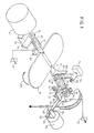
- the reference numeral 10 denotes a throttle valve.
- the unpublished European patent application 89105378 describes a throttle valve control to solve the task, in which the throttle valve is not closed by the cable, but the throttle cable only closes up to an angle of approximately 10 °, the remaining angular range between 0 and 10 ° is achieved by the electric motor adjusted.
- the haptic accelerator feel is affected by a change in the force line of the operation. This is changed by the measures proposed in the invention.
- the invention provides that the stop actuator for limiting the mechanical closure of the throttle valve is assigned directly to the component actuated by the throttle cable.
- the reference numeral 10 denotes a throttle valve which is installed in an intake manifold of an internal combustion engine, which in the illustration provided here would have to run vertically.
- the throttle valve 10 is shown in the closed state, it can be pivoted about a shaft 12, wherein a pivoting in the direction of arrow 100 moves the throttle valve 10 into its open position would bring.
- the shaft 12 is bent at one end at an angle to a radial extension 16, which is positively connected in terms of movement to the throttle valve 10, in the continuation of its axis 14 the shaft of an actuating element 18 is provided coaxially, which has a drive lever 22 and an output lever 28.
- the pivoting of the actuating part 18 is set via the drive lever 22, the output lever 28 transmits this pivoting in a manner to be described to the extension 16 which is positively connected in terms of movement to the throttle valve 10.
- the drive lever 22 or, as shown here, the output lever 28 continues to engage a return spring 24, the other end of which is articulated at point 26 on the housing side, this return spring 24, which is designed as a double spring for safety reasons, acts on the throttle valve 10 in its closed position.
- the output lever 28 has a driving pin 30 which runs parallel to the axis 14 and is in contact with the extension 16.
- a stop spring 32 biases the throttle valve 10 into its open position and thus the extension 16 into its contact position with the driving pin 30 of the actuator 18. It is essential that the spring 32 has a smaller spring force characteristic than the return spring 24, that is, it is softer.
- the spring 32 can connect the extension 16 directly to the output lever, but it can also, as shown in the drawing, exert a torque on the axis 12 with one end and be firmly articulated on the motor side with its other end 80.
- An extension 50 of the output lever 28 of the control part 18 has at its end 58 an adjustable stop screw 82 which comes into contact with a stop limiter 54 and thus the pivoting of the control part 18 limited in the closed position of the throttle valve 10.
- the actuating lever 18 is rotated in the direction of the open position of the throttle valve 10, that is to say in the direction of rotation of the arrow 100, by a pivot part 60 which can be pivoted by actuating a cable 20 which is connected to an accelerator pedal (not shown).
- the shaft 12 of the throttle valve 10 the axis of rotation of the adjusting part 18 and the axis of rotation of the pivoting part 60 are aligned coaxially with one another.
- a counter arm which is designed as an actuating lever 64, can be pivoted about this axis 14 with the aid of a cable lever 62 which is engaged by the cable 20.
- the actuating lever 64 has a driver 66 which presses on one side of the drive lever 22 of the actuating part 18 and thus moves this actuating part 18 in the direction of the open position.
- a return spring 70 is provided which ensures that when the accelerator pedal is not actuated and thus when the cable 20 is loose, the pivoting part 60 is moved into its zero position.
- a setpoint generator 72 which, as a sensor, emits an electrical signal that is representative of the load request that is generated by the driver when the accelerator pedal is actuated.
- the servomotor 42 is controlled by electronics. This can be a slip control, for example.
- the control electronics continue to take consumption-optimized characteristics into account, in accordance with those of the electric motor 42 can be controlled to open or close the throttle valve 10. Measures for damping the load change shock when the throttle valve 10 suddenly opens can also be taken into account here.
- the throttle valve 10 In order to counteract sudden slippage, a load change or also excessive consumption, the throttle valve 10 should be acted on in the direction of its closed position.
- the electric motor 42 is activated.
- a driver 38 presses on a radial pin 36 and rotates the shaft 12 in the opposite direction to the arrow 100.
- the extension 16 at the attachment point 88 disengages from the driver pin 30 of the actuating element 18, the spring 32 is loaded against its direction of action, and the throttle valve closed by the amount specified by the electronic logic.
- An actual value transmitter 68 which determines the actual degree of closure of the throttle valve 10, is assigned to either the shaft 12 or the shaft 40 and provides a value for the actual degree of throttle valve opening.
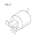
- the adjusting lever 64 has an extension 90 at its end remote from the axis, which comes to rest against a stop 94 when the accelerator pedal is not actuated, this position corresponds to an open position of the throttle valve of approximately 10 °.
- the stop 94 can be formed by a pin which can be extended or retracted by an electromagnet 92 and which is extended when the electromagnet 92 is not energized.
- the pin has two steps 96 and 98, the step 96 being the step which normally forms the attachment point for the extension 90.
- the swivel part 60 By pulling the accelerator pedal 20, the swivel part 60 is rotated about its axis and presses via the driver 66 in the stop 52 onto the drive lever 22 of the actuating part 18. As a result, the actuating part 18 is pivoted clockwise in the drawing, with swiveling over the dimension, which is predetermined by the pivoting of the pivoting part 60, in addition, for. B. when activation of a cruise control system is possible, in this case the drive lever 22 would no longer come into contact with the driver 66 of the swivel part 60 at point 52.
- the pivotal movement of the actuator 18 is transmitted via the driver pin 30 of the actuator 18 to the extension 16 which is connected to the shaft 12 of the throttle valve 10, since the spring 32 presses the extension 16 into contact with the driver pin 30 as long as no further forces Influence throttle valve 10.
- the maximum opening angle of the throttle valve 10 is predetermined, whereas the throttle valve 10 can close against the arrow direction 100 as long as the closing force overcomes the spring constant of the spring 32.
- the closing of the throttle valve between the maximum degree of opening, which is predetermined by the position of the gas cable 20 and the completely closed position, is set by the servomotor 42.
- the parameters for controlling the motor 42 are determined by correspondingly predetermined parameters stored in memories as well as by vehicle operating parameters (speed, speed, accelerator pedal characteristics and the like) and the values which the sensors 68 and 72 deliver, namely 68 for the actual position of the throttle valve 10 and 72 for the target position of the throttle valve 10, as is specified via the load request, which is determined by the accelerator pedal.
- the setpoint potentiometer 72 provides the controller with the information that the accelerator pedal is not actuated, as a result of which the corresponding idle setting takes place, which is controlled by the electric motor 42. In this range between 0 and 10 °, the exact position of the throttle valve 10 is thus triggered by the control of the electric motor 42.
- An important area for the application of the invention is the damping of the so-called load change shock. If the accelerator pedal is suddenly depressed, suddenly the pivoting part 60 and the adjusting part 18 are rotated and thus the maximum opening angle is adjusted upwards, however, the servomotor 42 adjusts the actual opening of the throttle valve 10 in order to achieve a softer response behavior which increases the acceleration comfort without noticeable loss of performance.
- the extension 90 comes to rest on the extended bolts 94, the various states being described below: If the system is working properly, the electromagnet housed in the housing 92 is not energized and has fully extended the bolt 94, so that the extension 90 comes to a first stop surface 96, which adjusts the mechanically predetermined minimum opening angle of the throttle valve in a corresponding manner.
- the second setting option is that the bolt 94 is partially retracted, this is advantageously done in that the electromagnet 92 is not fully excited to retract the bolt 94 completely, but is energized with a lower current, so that the bolt 94 is only partially retracted.
- the bolt 94 has a shoulder 102 at its end, so that a stop surface 98 adjoins the stop surface 96, which is offset with respect to the surface 96 and enables a further pivoting of the extension 90 in the direction of the closed position of the throttle valve 100 while idling.
- a third position is defined by the fact that the bolt 94 is fully retracted by the electromagnet in the housing 92 being excited, in which case no stop is defined for the extension 90 at all, the extent of the pivoting in the direction of the closed position of the throttle valve is accordingly determined by the Stop screw 82 determined.
- the function of the stop actuator during operation of the throttle valve is as follows: In normal operation, if there is no fault, the bolt 94 is fully extended, the stop 96 is effective and limits the extent of the rotation of the rope pulley in the direction of the closed position of the throttle valve by the extension 90.
- the potentiometer 72 detects the angular position of the pulley.
- the function of the stop actuator is to be checked at regular intervals under certain operating conditions; the second stop 98 is used for this purpose. If the operation ensures that the extension 90 is not in contact with the stop surface 96, since the driver of the vehicle holds the accelerator pedal depressed , the pin 94 can be pulled in half so that the stop surface 98 is effective. The next time the accelerator pedal is released, the extension 90 can thus pivot further towards the closed position of the throttle valve than is possible in normal operation, which the potentiometer 72 detects. This gives the feedback that the bolt 94 could be retracted. This has no influence on the function of the vehicle, since in normal operation the idle control is controlled by the electric motor 42 anyway.
- the bolt 94 can be extended again and normal operation can be maintained .
- This checking position can be carried out at regular time intervals, or also under certain operating conditions, for example during each switching operation in which the accelerator pedal is not operated briefly.
- the extension 90 can pivot further towards the closed position of the throttle valve so that the stop actuator 58 can come into effect.
- This can be achieved either by a third step in the bolt 54, which enables the extension 90 to be pivoted so far, or advantageously, as shown in the drawing, by the lack of a third stop surface, so that a further pivoting in the direction of the closed position is possible, as long as the stop 58 does not limit the further closing movement.
Landscapes
- Engineering & Computer Science (AREA)
- Chemical & Material Sciences (AREA)
- Combustion & Propulsion (AREA)
- Mechanical Engineering (AREA)
- General Engineering & Computer Science (AREA)
- Control Of Throttle Valves Provided In The Intake System Or In The Exhaust System (AREA)
Applications Claiming Priority (2)
| Application Number | Priority Date | Filing Date | Title |
|---|---|---|---|
| DE4011183 | 1990-04-06 | ||
| DE4011183A DE4011183A1 (de) | 1990-04-06 | 1990-04-06 | Anschlagsteller |
Publications (2)
| Publication Number | Publication Date |
|---|---|
| EP0454971A1 true EP0454971A1 (fr) | 1991-11-06 |
| EP0454971B1 EP0454971B1 (fr) | 1994-11-23 |
Family
ID=6403918
Family Applications (1)
| Application Number | Title | Priority Date | Filing Date |
|---|---|---|---|
| EP91103586A Expired - Lifetime EP0454971B1 (fr) | 1990-04-06 | 1991-03-08 | Positionneur de butée pour papillon des gaz |
Country Status (2)
| Country | Link |
|---|---|
| EP (1) | EP0454971B1 (fr) |
| DE (2) | DE4011183A1 (fr) |
Family Cites Families (2)
| Publication number | Priority date | Publication date | Assignee | Title |
|---|---|---|---|---|
| DE3524911A1 (de) * | 1985-07-12 | 1987-01-15 | Vdo Schindling | Einrichtung zur regelung der leerlaufdrehzahl eines ottomotors, insbesondere in einem kraftfahrzeug |
| DE3843147A1 (de) * | 1988-12-22 | 1990-06-28 | Vdo Schindling | Stelleinrichtung fuer eine zumesseinrichtung einer brennkraftmaschine |
-
1990
- 1990-04-06 DE DE4011183A patent/DE4011183A1/de not_active Withdrawn
-
1991
- 1991-03-08 EP EP91103586A patent/EP0454971B1/fr not_active Expired - Lifetime
- 1991-03-08 DE DE59103563T patent/DE59103563D1/de not_active Expired - Fee Related
Non-Patent Citations (5)
| Title |
|---|
| PATENT ABSTRACTS OF JAPAN, Band 11. Nr. 168 (M-594), 29. Mai 1987; & JP-A-62 003 159 (HONDA) 09-01-1987 * |
| PATENT ABSTRACTS OF JAPAN, Band 12, Nr. 336 (M-739), 9. September 1988; & JP-A-63 097 840 (HITACHI) 28-04-1988 * |
| PATENT ABSTRACTS OF JAPAN, Band 9, Nr. 209 (M-407), 27. August 1985; & JP-A-60 069 238 (MAZDA) 19-04-1985 * |
| PATENT ABSTRACTS OF JAPAN, Band 9, Nr. 219 (M-410), 6. September 1985; & JP-A-60 079 129 (NIHON) 04-05-1985 * |
| PATENT ABSTRACTS OF JAPAN, Band 9, Nr. 303 (M-434), 30. November 1985; & JP-A-60 142 027 (MAZDA) 27-07-1985 * |
Also Published As
| Publication number | Publication date |
|---|---|
| DE59103563D1 (de) | 1995-01-05 |
| EP0454971B1 (fr) | 1994-11-23 |
| DE4011183A1 (de) | 1991-10-10 |
Similar Documents
| Publication | Publication Date | Title |
|---|---|---|
| EP0389649B1 (fr) | Papillon d'accélérateur | |
| DE69103002T2 (de) | Drosselklappe. | |
| DE4243893C2 (de) | Vorrichtung zum Steuern einer Drosselklappe einer Brennkraftmaschine | |
| EP0412237B1 (fr) | Papillon | |
| DE4430510A1 (de) | Drosselvorrichtung für einen Verbrennungsmotor | |
| DE3831257A1 (de) | Einrichtung zur steuerung des oeffnungsgrades eines drosselventils an einem fahrzeugmotor | |
| DE4441155A1 (de) | Drosselklappen-Regelvorrichtung | |
| DE19812944A1 (de) | Fahrsteuereinrichtung für den Motor eines Fahrzeugs | |
| EP0269780B1 (fr) | Dispositif de transmission de la position d'un élément de commande actionnable par le conducteur d'un véhicule | |
| EP0483448B1 (fr) | Dispositif de réglage de charge | |
| EP0558802A2 (fr) | Dispositif de commande de papillon | |
| DE3711779A1 (de) | Drosselklappe | |
| EP0378737B1 (fr) | Dispositif de réglage de la charge | |
| DE3800876A1 (de) | Leistungssteller fuer eine brennkraftmaschine | |
| EP0456904B1 (fr) | Dispositif de réglage de la puissance | |
| EP0454971B1 (fr) | Positionneur de butée pour papillon des gaz | |
| DE4221768C2 (de) | Verfahren und Vorrichtung zur Steuerung einer Verstelleinrichtung in einem Fahrzeug | |
| EP0488016B1 (fr) | Dispositif de commande de la puissance d'un moteur à combustion interne notamment pour véhicule automobile | |
| EP0478884B1 (fr) | Dispositif de réglage de charge | |
| EP0540811B1 (fr) | Dispositif pour le positionnement d'un clapet d'étranglement | |
| DE4216788A1 (de) | Vorrichtung zum Verstellen einer Drosselklappe | |
| EP0455882A2 (fr) | Dispositif de réglage pour un papillon des gaz | |
| DE4013824C2 (de) | Lastverstelleinrichtung | |
| DE19721239A1 (de) | Vorrichtung zur Betätigung der Drosselklappe eines Verbrennungsmotors | |
| DE102006036427B4 (de) | Einrichtung und Verfahren zur Betätigung einer Leistungssteuerungseinrichtung einer Brennkraftmaschine |
Legal Events
| Date | Code | Title | Description |
|---|---|---|---|
| PUAI | Public reference made under article 153(3) epc to a published international application that has entered the european phase |
Free format text: ORIGINAL CODE: 0009012 |
|
| AK | Designated contracting states |
Kind code of ref document: A1 Designated state(s): DE FR GB IT |
|
| 17P | Request for examination filed |
Effective date: 19911129 |
|
| 17Q | First examination report despatched |
Effective date: 19930504 |
|
| ITF | It: translation for a ep patent filed | ||
| GRAA | (expected) grant |
Free format text: ORIGINAL CODE: 0009210 |
|
| AK | Designated contracting states |
Kind code of ref document: B1 Designated state(s): DE FR GB IT |
|
| GBT | Gb: translation of ep patent filed (gb section 77(6)(a)/1977) |
Effective date: 19941206 |
|
| REF | Corresponds to: |
Ref document number: 59103563 Country of ref document: DE Date of ref document: 19950105 |
|
| ET | Fr: translation filed | ||
| PLBE | No opposition filed within time limit |
Free format text: ORIGINAL CODE: 0009261 |
|
| STAA | Information on the status of an ep patent application or granted ep patent |
Free format text: STATUS: NO OPPOSITION FILED WITHIN TIME LIMIT |
|
| 26N | No opposition filed | ||
| REG | Reference to a national code |
Ref country code: GB Ref legal event code: IF02 |
|
| PGFP | Annual fee paid to national office [announced via postgrant information from national office to epo] |
Ref country code: DE Payment date: 20040305 Year of fee payment: 14 |
|
| PGFP | Annual fee paid to national office [announced via postgrant information from national office to epo] |
Ref country code: GB Payment date: 20050308 Year of fee payment: 15 |
|
| PGFP | Annual fee paid to national office [announced via postgrant information from national office to epo] |
Ref country code: FR Payment date: 20050316 Year of fee payment: 15 |
|
| PG25 | Lapsed in a contracting state [announced via postgrant information from national office to epo] |
Ref country code: DE Free format text: LAPSE BECAUSE OF NON-PAYMENT OF DUE FEES Effective date: 20051001 |
|
| PG25 | Lapsed in a contracting state [announced via postgrant information from national office to epo] |
Ref country code: GB Free format text: LAPSE BECAUSE OF NON-PAYMENT OF DUE FEES Effective date: 20060308 |
|
| PGFP | Annual fee paid to national office [announced via postgrant information from national office to epo] |
Ref country code: IT Payment date: 20060331 Year of fee payment: 16 |
|
| GBPC | Gb: european patent ceased through non-payment of renewal fee |
Effective date: 20060308 |
|
| REG | Reference to a national code |
Ref country code: FR Ref legal event code: ST Effective date: 20061130 |
|
| PG25 | Lapsed in a contracting state [announced via postgrant information from national office to epo] |
Ref country code: FR Free format text: LAPSE BECAUSE OF NON-PAYMENT OF DUE FEES Effective date: 20060331 |
|
| PG25 | Lapsed in a contracting state [announced via postgrant information from national office to epo] |
Ref country code: IT Free format text: LAPSE BECAUSE OF NON-PAYMENT OF DUE FEES Effective date: 20070308 |