EP0455882A2 - Dispositif de réglage pour un papillon des gaz - Google Patents
Dispositif de réglage pour un papillon des gaz Download PDFInfo
- Publication number
- EP0455882A2 EP0455882A2 EP90124832A EP90124832A EP0455882A2 EP 0455882 A2 EP0455882 A2 EP 0455882A2 EP 90124832 A EP90124832 A EP 90124832A EP 90124832 A EP90124832 A EP 90124832A EP 0455882 A2 EP0455882 A2 EP 0455882A2
- Authority
- EP
- European Patent Office
- Prior art keywords
- throttle valve
- gear
- valve shaft
- adjusting device
- driver
- Prior art date
- Legal status (The legal status is an assumption and is not a legal conclusion. Google has not performed a legal analysis and makes no representation as to the accuracy of the status listed.)
- Granted
Links
Images
Classifications
-
- F—MECHANICAL ENGINEERING; LIGHTING; HEATING; WEAPONS; BLASTING
- F02—COMBUSTION ENGINES; HOT-GAS OR COMBUSTION-PRODUCT ENGINE PLANTS
- F02D—CONTROLLING COMBUSTION ENGINES
- F02D11/00—Arrangements for, or adaptations to, non-automatic engine control initiation means, e.g. operator initiated
- F02D11/06—Arrangements for, or adaptations to, non-automatic engine control initiation means, e.g. operator initiated characterised by non-mechanical control linkages, e.g. fluid control linkages or by control linkages with power drive or assistance
- F02D11/10—Arrangements for, or adaptations to, non-automatic engine control initiation means, e.g. operator initiated characterised by non-mechanical control linkages, e.g. fluid control linkages or by control linkages with power drive or assistance of the electric type
-
- B—PERFORMING OPERATIONS; TRANSPORTING
- B60—VEHICLES IN GENERAL
- B60K—ARRANGEMENT OR MOUNTING OF PROPULSION UNITS OR OF TRANSMISSIONS IN VEHICLES; ARRANGEMENT OR MOUNTING OF PLURAL DIVERSE PRIME-MOVERS IN VEHICLES; AUXILIARY DRIVES FOR VEHICLES; INSTRUMENTATION OR DASHBOARDS FOR VEHICLES; ARRANGEMENTS IN CONNECTION WITH COOLING, AIR INTAKE, GAS EXHAUST OR FUEL SUPPLY OF PROPULSION UNITS IN VEHICLES
- B60K28/00—Safety devices for propulsion-unit control, specially adapted for, or arranged in, vehicles, e.g. preventing fuel supply or ignition in the event of potentially dangerous conditions
- B60K28/10—Safety devices for propulsion-unit control, specially adapted for, or arranged in, vehicles, e.g. preventing fuel supply or ignition in the event of potentially dangerous conditions responsive to conditions relating to the vehicle
- B60K28/16—Safety devices for propulsion-unit control, specially adapted for, or arranged in, vehicles, e.g. preventing fuel supply or ignition in the event of potentially dangerous conditions responsive to conditions relating to the vehicle responsive to, or preventing, spinning or skidding of wheels
-
- F—MECHANICAL ENGINEERING; LIGHTING; HEATING; WEAPONS; BLASTING
- F02—COMBUSTION ENGINES; HOT-GAS OR COMBUSTION-PRODUCT ENGINE PLANTS
- F02D—CONTROLLING COMBUSTION ENGINES
- F02D11/00—Arrangements for, or adaptations to, non-automatic engine control initiation means, e.g. operator initiated
- F02D11/06—Arrangements for, or adaptations to, non-automatic engine control initiation means, e.g. operator initiated characterised by non-mechanical control linkages, e.g. fluid control linkages or by control linkages with power drive or assistance
- F02D11/10—Arrangements for, or adaptations to, non-automatic engine control initiation means, e.g. operator initiated characterised by non-mechanical control linkages, e.g. fluid control linkages or by control linkages with power drive or assistance of the electric type
- F02D2011/101—Arrangements for, or adaptations to, non-automatic engine control initiation means, e.g. operator initiated characterised by non-mechanical control linkages, e.g. fluid control linkages or by control linkages with power drive or assistance of the electric type characterised by the means for actuating the throttles
- F02D2011/103—Arrangements for, or adaptations to, non-automatic engine control initiation means, e.g. operator initiated characterised by non-mechanical control linkages, e.g. fluid control linkages or by control linkages with power drive or assistance of the electric type characterised by the means for actuating the throttles at least one throttle being alternatively mechanically linked to the pedal or moved by an electric actuator
Definitions
- Load adjustment device with a throttle valve determining the performance of an internal combustion engine which is connected in a rotationally fixed manner to a throttle valve shaft mounted in the throttle valve housing, a control element acting on the throttle valve shaft, which cooperates with a driver coupled to an accelerator pedal and can be controlled by means of an electric actuator interacting with an electronic control device which controls the position of the throttle valve in the idling range (LLmin - LLmax) via a first gear.
- load adjustment devices Of particular importance in load adjustment devices is the mastery of the load state of idling, in which only one of the internal combustion engines minimum power is delivered, but this may be the case in motor vehicles, in certain circumstances, for consumers who require high performance, such as blowers, rear window heating, air conditioning, etc.
- regulation of the load adjustment device between a maximum idle position is necessary. If the control fails, the actuator or control element must be in an idle emergency position.
- load adjustment devices of the type mentioned are generally used where the accelerator pedal and the actuator are electronically linked.
- the accelerator pedal is coupled to the driver and this to the control element.
- a setpoint detection element cooperating with this and an actual value detection element interacting with it and acting on the electric actuator are provided, the electric actuator being controllable by the electronic control device as a function of the detected values.
- the electrical link between the accelerator pedal and the actuator with the electronic control device connected in between enables the accelerator pedal and the driver coupled to it to be used to set predetermined setpoint positions in relation to the actual values represented by the position of the control element and actuator and to check for existing or missing plausibility conditions , so that in the presence or absence of certain plausibility conditions there is the possibility of actuation via the electronic control device of the electric actuator to have a corrective effect on the actuator, which can be designed, for example, as a throttle valve or injection pump.
- an intervention by the electronic control device to avoid wheel slip when starting due to excessive power input by the accelerator pedal can be provided.
- Other automatic interventions in the load adjustment device are conceivable, for example, in the case of automatic switching operations of a transmission, a speed limit control or the previously discussed idle control of the internal combustion engine.
- the invention has for its object to provide a load adjustment device of the type mentioned, which ensures safe and accurate control of the internal combustion engine over the entire idling range and a response to the anti-slip control device with a structurally simple design.
- the object is achieved in that, in addition to the one transmission, a further transmission is provided which can be engaged above the idling range (LLmax). Due to the configuration of the load adjusting device according to the invention, regulation can be carried out upwards (LLmax) and downwards (LLmin) over the entire idling range by means of a single actuator. Furthermore, it is possible to ensure that the internal combustion engine is shut down by means of the additional gear in the anti-slip control area (ASR).
- ASR anti-slip control area
- the further gear unit which connects the actuator designed as an electric motor to the throttle valve shaft, can only be engaged when the further gear unit is ineffective brought. This ensures that the first or further transmission becomes effective only in the anti-slip control area and that the internal combustion engine is not adjusted, so that if the other control elements fail, the internal combustion engine is not brought up in an uncontrolled manner.
- the first gear has a driven disk arranged on the output shaft of the electric motor and a drive disk operatively connected to the throttle valve shaft, which can then be brought into engagement with the driven disk when the second gear is uncoupled from the throttle valve shaft .
- the driven pulley is designed as a gear segment which is arranged on a hollow shaft arranged on the throttle valve shaft in a rotationally fixed manner. This allows two gears to be easily accommodated in the smallest space.
- the use of the gear segment ensures that the first gear is only used to regulate the internal combustion engine when the first gear is uncoupled.
- the gear segment advantageously offers the possibility of establishing the non-positive connection for the first transmission at a precisely defined point in time when the second transmission has been deactivated, i.e. the idle control range has been left.
- the second gear is connected downstream of the first gear, which in the direction of rotation for opening the throttle valve with a on the throttle valve shaft arranged driver is operatively connected. It is also advantageous that the second gear has a cam which can be brought into engagement via a handlebar with the driver arranged on the throttle valve shaft to open the throttle valve and that the cam has an Archimedes spiral in which a crouch connected to the handlebar is guided is, with the Archimedes spiral adjoining a circular arc piece arranged concentrically to the axis of rotation, in which the cam is received when the driven disk is in engagement with the gear segment. It is also advantageous that the Archimedes spiral and the arc piece are separated from each other by a rest point. By means of the Archimedes spiral and the handlebar engaged with it, relatively large transmission ratios can be achieved, it being advantageous that the slope is not self-locking.
- a second driver is arranged on the throttle valve shaft, against which a lever arranged on the hollow shaft can be brought into contact in the direction of closing the throttle valve.
- the throttle valve shaft can be adjusted in a simple manner by means of the second transmission over the entire idling range, without influencing the first transmission.
- the first gear acts only outside the idle control range via the first driver on the throttle valve shaft in the direction of closing, so that when the anti-slip control is used, the internal combustion engine is always regulated down. Since the Archimedes spiral in a circular arc piece passes over, it is ensured that the electric motor does not cause a pivoting of the link interacting with the cam disc, especially since the first transmission is then also in use.
- the lever arranged on the hollow shaft can be brought into contact with the driver of the throttle valve shaft by means of a spring. In this way it is ensured that the first transmission takes effect immediately when the second transmission is uncoupled, so that the throttle valve can then be adjusted in the direction of closing when the first transmission is engaged.
- the accelerator pedal is operatively connected via a driver and a spring to a freewheel hook, which has two spaced drivers, between which a second lever arranged on the throttle valve shaft between a lower idle position (LLmin) and an upper idle position (LLmax) is adjustable, whereby the second lever can be brought to bear against the driver via the spring connected to the throttle valve shaft, by means of which the throttle valve can be adjusted in the opening direction.
- the driver connected to the accelerator pedal is adjustable between a first stop in the idling direction (LL) and a second stop in the full load direction (VL).
- the handlebar can be preloaded into the emergency running position by means of an emergency running spring.
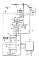
- the parts shown in the frame 18 according to Figure 1 form an actuator or a load adjustment device 10, which are combined in one unit.
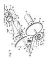
- the load adjustment device 10 includes a servomotor or electric motor 14, which is connected in terms of drive via a first gear 33, which is only indicated schematically, to a hollow shaft 39 and, via a second gear 34, to a throttle valve shaft 36 of a throttle valve 9.
- the actuating forces of the electric motor 14 are transmitted to the throttle valve 9 via the gears 33, 34, and an adjustment to the desired position is thereby brought about.
- the load adjustment device 10 can be adjusted by means of an accelerator pedal 1, wherein by actuating the accelerator pedal 1 a lever 2 is shifted between an idle stop LL and a full load stop VL and is biased in the idle direction LL by a return spring 5.
- the accelerator pedal 1 is connected to a driver 4 by means of an accelerator cable 3, so that when the accelerator pedal 1 is actuated, the driver 4 is displaced in the direction of the full load stop VL.
- Return springs 6 are connected to the driver 4 and bias them in the idling direction LL. As long as the throttle cable 3 is not acted upon, the driver 4 rests against the idling stop LL assigned to it.
- the driver 4 interacts via a spring 46 with a freewheel hook 47, which according to the invention consists of a pivotably mounted linkage 61 with a plate 62 attached to it. There are two spaced-apart drivers 49, 51 on the plate 62, which form a recess in which a first control element part 8a is received with a lever 52.
- the freewheel hook 47 is pulled by means of the spring 46 against a stop 63 provided on the driver 4, so that the freewheel hook 47 can move away from it.
- the first control element part 8a consists of the lever 52 and a throttle valve shaft 36 receiving it.
- the load adjustment device 10 has a second control element part designed as a link 43 of a transmission 34 8b, which is drive-connected to an electric motor 14 via this gear 34.
- a translation of the servomotor movement takes place by means of a gear 34, which is described in more detail below in terms of its structure and its function.
- a third control element part 8c designed as a hollow shaft 39 is provided, which can also be coupled to the electric motor 14 via a further or first gear 33.
- the end of the hollow shaft 39 has a lever 45 which can be brought into abutment against a driver 44 arranged on the throttle valve shaft 36, so that the lever 45 and the driver 44 represent a one-way clutch.
- a spring 22 is connected to the hollow shaft 39, the other end of which is connected to a fixed point 63 in the load adjustment device 10 and prestresses the hollow shaft 39 and thus also the throttle valve shaft 36 with the associated throttle valve 9 in the direction of the minimal idling position (LLmin).
- the first control element part 8a In this position (LLmin), the first control element part 8a also lies with its lever 52 against the driver 49, so that the freewheel hook 47 is prestressed in the idling direction LLmin over the entire idle control range (LL min to LL max ). If, for example, the accelerator pedal 1 is actuated, the throttle valve shaft 36 is actuated via the driver 49 outside the idle control range, ie part-load or full-load operation.
- the lever 45 bears against the driver 44. Furthermore, the throttle valve shaft 36 is operatively connected to the link 43 of the second transmission 34 via the driver 42.
- the second gear 34 consists of the link 43, which is pivotally arranged on a pin 60.
- the link 43 has a cam 55 at its end opposite the pin 60. This is received in groove 54 provided in a cam disk 41.
- the groove 54 has the shape of an Archimedes spiral and can advantageously extend over a total angle of 720 degrees, so that within two revolutions of the electric motor 14 an adjustment of the handlebar 43 and thus an adjustment of the throttle valve shaft 36 in the idle control range between LLmin and LLmax only in the direction of opening the throttle valve 9.
- the second gear 34 has the advantage that large gear ratios are possible in a simple manner, for example 1:30 to 1:40 and more.
- the output shaft 38 is rotated the Eektromotors 14 to 56o o.
- the emergency running spring 20 ensures that in the event of a defect in an electronic control device 17 or the electric motor 14, the resistance moments of the electric motor 14 or the transmission parts are overcome and the throttle valve 9 is returned to the idling emergency position (LLnot).
- the actual value detection device 19 is advantageously mounted in the area of the pivotable freewheel hook 47, while the setpoint value detection device 65 is provided in the area of the driver 4.
- the gear 33 upstream of the second gear 34 has an output disk 35 arranged on the output shaft 38 of the electric motor 14. This is operatively connected to the throttle valve shaft 36 via a drive disk 37 when the second gear 34 no longer has any influence on the throttle valve shaft 36.
- the groove 54 is followed by a circular arc piece 57 which is arranged concentrically to the axis of rotation 56 and in which the cam 55 is received when the drive disk 35 is in engagement with the drive disk 37, which can be designed as a gear segment 40.
- the gear segment 40 is arranged on the hollow shaft 39, which exerts an actuating force with its lever 45 on the driver 44 of the throttle valve shaft 36 and adjusts it in the direction of closing the throttle valve 9.
- the two gears 33, 34 are matched to one another in such a way that the first gearing 33 is only used above the idling range, ie in the part-load or full-load range of the internal combustion engine.
- the lever 45 is pulled by means of the spring 22 against the driver 44 of the throttle valve shaft 36, so that when the electric motor 14 is switched on, the throttle valve shaft 36 via the first gear 33 only in the direction of closing the Throttle valve 9 can be rotated.
- ASR anti-slip rule
- the electronic control device 17 which contains conditioning, logic and control circuits, is indicated schematically.
- the control device 17 stores values for vehicle adaptation and processes the digital or digitized values of various input variables, which then regulate the desired position of the throttle valve 9 via an analog part.
- the electronic control device 17 interacts with an actual value detection device 19 belonging to the control element parts 8a, 8b and a setpoint detection device 65 assigned to the driver 4 and determining the respective position of the driver 4.
- a potentiometer 66 is assigned to the first actual value detection device 19 and a second potentiometer 67 to the setpoint value detection device 65.
- the control device 17 has the task of acquiring and comparing all of the input signals, for example speed, by means of the potentiometers 66, 67 (FIG. 2). If, for example, the vehicle speed deviates from the setpoint, the actuator is activated until the specified speed is reached.
- the electronic control device 17 also detects signals via an idle contact 68, which is activated by the driver 4, when it comes to rest against the idle stop LL assigned to it.
- the electronic control device 17 serves the purpose of building up a safety logic relating to the control of the first and second control element parts 8a, 8b. As soon as the electronic control device 17 or the electric motor 14 no longer function properly, the throttle valve 9 is moved into the idle emergency position LL not by the spring 22, which is biased in the direction of the maximum idle position.
- regulation can be carried out upwards (LLmax) and downwards (LLmin) over the entire idling range by means of a single actuator. Furthermore, it is possible to ensure that the internal combustion engine is shut down in the anti-slip control case (ASR) by means of the second gear 34 outside the idling control range.
- ASR anti-slip control case
Landscapes
- Engineering & Computer Science (AREA)
- Chemical & Material Sciences (AREA)
- Combustion & Propulsion (AREA)
- Mechanical Engineering (AREA)
- Transportation (AREA)
- General Engineering & Computer Science (AREA)
- Control Of Throttle Valves Provided In The Intake System Or In The Exhaust System (AREA)
Applications Claiming Priority (2)
| Application Number | Priority Date | Filing Date | Title |
|---|---|---|---|
| DE4014555 | 1990-05-07 | ||
| DE4014555A DE4014555A1 (de) | 1990-05-07 | 1990-05-07 | Lastverstelleinrichtung |
Publications (3)
| Publication Number | Publication Date |
|---|---|
| EP0455882A2 true EP0455882A2 (fr) | 1991-11-13 |
| EP0455882A3 EP0455882A3 (en) | 1992-02-26 |
| EP0455882B1 EP0455882B1 (fr) | 1994-08-03 |
Family
ID=6405844
Family Applications (1)
| Application Number | Title | Priority Date | Filing Date |
|---|---|---|---|
| EP90124832A Expired - Lifetime EP0455882B1 (fr) | 1990-05-07 | 1990-12-19 | Dispositif de réglage pour un papillon des gaz |
Country Status (2)
| Country | Link |
|---|---|
| EP (1) | EP0455882B1 (fr) |
| DE (2) | DE4014555A1 (fr) |
Cited By (2)
| Publication number | Priority date | Publication date | Assignee | Title |
|---|---|---|---|---|
| EP0570623A3 (en) * | 1992-05-21 | 1996-05-15 | Vdo Schindling | Device for adjusting a throttle valve |
| EP0810359A3 (fr) * | 1996-06-01 | 1998-05-06 | Mannesmann VDO AG | Dispositif de commande de charge |
Families Citing this family (1)
| Publication number | Priority date | Publication date | Assignee | Title |
|---|---|---|---|---|
| DE4215315C1 (en) * | 1992-05-09 | 1993-09-23 | Vdo Adolf Schindling Ag, 60487 Frankfurt, De | Rotation angle sensor for IC engine throttle valve - feeds signals via R=2R D=A converter and single transmission line to remote A=D converter and evaluation circuit |
Family Cites Families (5)
| Publication number | Priority date | Publication date | Assignee | Title |
|---|---|---|---|---|
| EP0030022B1 (fr) * | 1979-11-30 | 1984-09-19 | Yamaha Hatsudoki Kabushiki Kaisha | Dispositif de commande de papillon pour moteur |
| US4411231A (en) * | 1982-04-16 | 1983-10-25 | Ford Motor Company | Carburetor throttle valve actuator |
| US4526060A (en) * | 1982-09-28 | 1985-07-02 | Ford Motor Company | Carburetor throttle valve actuator |
| DE3641244C3 (de) * | 1986-12-03 | 1995-02-23 | Vdo Schindling | Anordnung für ein Kraftfahrzeug |
| DE3900437C1 (fr) * | 1989-01-10 | 1989-11-16 | Vdo Adolf Schindling Ag, 6000 Frankfurt, De |
-
1990
- 1990-05-07 DE DE4014555A patent/DE4014555A1/de not_active Withdrawn
- 1990-12-19 EP EP90124832A patent/EP0455882B1/fr not_active Expired - Lifetime
- 1990-12-19 DE DE59006706T patent/DE59006706D1/de not_active Expired - Fee Related
Cited By (2)
| Publication number | Priority date | Publication date | Assignee | Title |
|---|---|---|---|---|
| EP0570623A3 (en) * | 1992-05-21 | 1996-05-15 | Vdo Schindling | Device for adjusting a throttle valve |
| EP0810359A3 (fr) * | 1996-06-01 | 1998-05-06 | Mannesmann VDO AG | Dispositif de commande de charge |
Also Published As
| Publication number | Publication date |
|---|---|
| DE4014555A1 (de) | 1991-11-14 |
| DE59006706D1 (de) | 1994-09-08 |
| EP0455882B1 (fr) | 1994-08-03 |
| EP0455882A3 (en) | 1992-02-26 |
Similar Documents
| Publication | Publication Date | Title |
|---|---|---|
| EP0389649B1 (fr) | Papillon d'accélérateur | |
| DE69103002T2 (de) | Drosselklappe. | |
| EP0413081A1 (fr) | Dispositif de réglage de charge | |
| EP0413082B1 (fr) | Dispositif de réglage de charge | |
| EP0208222A2 (fr) | Dispositif de commande de la vitesse de ralenti pour moteur à allumage commandé, plus particulièrement pour véhicule | |
| EP0412237B1 (fr) | Papillon | |
| EP0269780B1 (fr) | Dispositif de transmission de la position d'un élément de commande actionnable par le conducteur d'un véhicule | |
| DE3918852A1 (de) | Elektrisch ansteuerbare drosselklappenbetaetigungseinrichtung fuer brennkraftmaschinen | |
| EP0483448A1 (fr) | Dispositif de réglage de charge | |
| EP0456904B1 (fr) | Dispositif de réglage de la puissance | |
| EP0378737B1 (fr) | Dispositif de réglage de la charge | |
| EP0378736B1 (fr) | Dispositif de réglage de la charge | |
| WO1999010642A1 (fr) | Dispositif d'ajustement de charge | |
| EP0455882A2 (fr) | Dispositif de réglage pour un papillon des gaz | |
| EP0455877B1 (fr) | Dispositif de réglage de charge | |
| EP0455883B1 (fr) | Dispositif de réglage pour un papillon des gaz | |
| DE3628538A1 (de) | Anordnung fuer ein kraftfahrzeug | |
| EP0374354A2 (fr) | Dispositif de positionnement d'un dispositif d'admission d'un moteur | |
| EP0540811B1 (fr) | Dispositif pour le positionnement d'un clapet d'étranglement | |
| DE4005905A1 (de) | Elektromotorisch betaetigbare leistungssteuervorrichtung einer brennkraftmaschine | |
| EP0570623A2 (fr) | Dispositif d'ajustement de papillon d'admission | |
| EP0454971B1 (fr) | Positionneur de butée pour papillon des gaz | |
| DE19721239A1 (de) | Vorrichtung zur Betätigung der Drosselklappe eines Verbrennungsmotors | |
| DE4040217A1 (de) | Einrichtung zur betaetigung der drosselklappe eines verbrennungsmotors | |
| DE4124972A1 (de) | Lastverstelleinrichtung fuer eine antriebsmaschine |
Legal Events
| Date | Code | Title | Description |
|---|---|---|---|
| PUAI | Public reference made under article 153(3) epc to a published international application that has entered the european phase |
Free format text: ORIGINAL CODE: 0009012 |
|
| AK | Designated contracting states |
Kind code of ref document: A2 Designated state(s): DE FR GB IT SE |
|
| PUAL | Search report despatched |
Free format text: ORIGINAL CODE: 0009013 |
|
| AK | Designated contracting states |
Kind code of ref document: A3 Designated state(s): DE FR GB IT SE |
|
| 17P | Request for examination filed |
Effective date: 19920409 |
|
| 17Q | First examination report despatched |
Effective date: 19930908 |
|
| GRAA | (expected) grant |
Free format text: ORIGINAL CODE: 0009210 |
|
| AK | Designated contracting states |
Kind code of ref document: B1 Designated state(s): DE FR GB IT SE |
|
| PG25 | Lapsed in a contracting state [announced via postgrant information from national office to epo] |
Ref country code: IT Free format text: LAPSE BECAUSE OF FAILURE TO SUBMIT A TRANSLATION OF THE DESCRIPTION OR TO PAY THE FEE WITHIN THE PRESCRIBED TIME-LIMIT;WARNING: LAPSES OF ITALIAN PATENTS WITH EFFECTIVE DATE BEFORE 2007 MAY HAVE OCCURRED AT ANY TIME BEFORE 2007. THE CORRECT EFFECTIVE DATE MAY BE DIFFERENT FROM THE ONE RECORDED. Effective date: 19940803 Ref country code: GB Effective date: 19940803 |
|
| ET | Fr: translation filed | ||
| REF | Corresponds to: |
Ref document number: 59006706 Country of ref document: DE Date of ref document: 19940908 |
|
| PG25 | Lapsed in a contracting state [announced via postgrant information from national office to epo] |
Ref country code: SE Effective date: 19941103 |
|
| GBV | Gb: ep patent (uk) treated as always having been void in accordance with gb section 77(7)/1977 [no translation filed] |
Effective date: 19940803 |
|
| PLBE | No opposition filed within time limit |
Free format text: ORIGINAL CODE: 0009261 |
|
| STAA | Information on the status of an ep patent application or granted ep patent |
Free format text: STATUS: NO OPPOSITION FILED WITHIN TIME LIMIT |
|
| 26N | No opposition filed | ||
| PG25 | Lapsed in a contracting state [announced via postgrant information from national office to epo] |
Ref country code: FR Effective date: 19950831 |
|
| REG | Reference to a national code |
Ref country code: FR Ref legal event code: ST |
|
| PGFP | Annual fee paid to national office [announced via postgrant information from national office to epo] |
Ref country code: DE Payment date: 19961108 Year of fee payment: 7 |
|
| PG25 | Lapsed in a contracting state [announced via postgrant information from national office to epo] |
Ref country code: DE Free format text: LAPSE BECAUSE OF NON-PAYMENT OF DUE FEES Effective date: 19980901 |