EP0455041A1 - Dispositif pour serrer un instrument de traitement de substrat - Google Patents
Dispositif pour serrer un instrument de traitement de substrat Download PDFInfo
- Publication number
- EP0455041A1 EP0455041A1 EP91106029A EP91106029A EP0455041A1 EP 0455041 A1 EP0455041 A1 EP 0455041A1 EP 91106029 A EP91106029 A EP 91106029A EP 91106029 A EP91106029 A EP 91106029A EP 0455041 A1 EP0455041 A1 EP 0455041A1
- Authority
- EP
- European Patent Office
- Prior art keywords
- knife
- hub
- forces
- cutting
- pressing
- Prior art date
- Legal status (The legal status is an assumption and is not a legal conclusion. Google has not performed a legal analysis and makes no representation as to the accuracy of the status listed.)
- Granted
Links
- 238000003825 pressing Methods 0.000 title claims abstract description 7
- 239000000758 substrate Substances 0.000 claims description 14
- 238000003754 machining Methods 0.000 claims description 12
- 239000000696 magnetic material Substances 0.000 claims description 4
- 229910052751 metal Inorganic materials 0.000 claims description 3
- 239000002184 metal Substances 0.000 claims description 3
- 239000004033 plastic Substances 0.000 claims description 3
- 229920003023 plastic Polymers 0.000 claims description 3
- 239000011888 foil Substances 0.000 claims description 2
- 150000002739 metals Chemical class 0.000 claims description 2
- 238000005520 cutting process Methods 0.000 description 22
- 239000000463 material Substances 0.000 description 6
- 229910000831 Steel Inorganic materials 0.000 description 5
- 230000000694 effects Effects 0.000 description 5
- 239000010959 steel Substances 0.000 description 5
- 238000000034 method Methods 0.000 description 4
- 230000001965 increasing effect Effects 0.000 description 3
- 238000010276 construction Methods 0.000 description 2
- 239000004744 fabric Substances 0.000 description 2
- 239000000123 paper Substances 0.000 description 2
- 229910052782 aluminium Inorganic materials 0.000 description 1
- XAGFODPZIPBFFR-UHFFFAOYSA-N aluminium Chemical compound [Al] XAGFODPZIPBFFR-UHFFFAOYSA-N 0.000 description 1
- 230000001627 detrimental effect Effects 0.000 description 1
- 230000005684 electric field Effects 0.000 description 1
- 239000010408 film Substances 0.000 description 1
- 238000007373 indentation Methods 0.000 description 1
- 239000002985 plastic film Substances 0.000 description 1
- 229920006255 plastic film Polymers 0.000 description 1
- 238000004804 winding Methods 0.000 description 1
Images


Classifications
-
- B—PERFORMING OPERATIONS; TRANSPORTING
- B26—HAND CUTTING TOOLS; CUTTING; SEVERING
- B26D—CUTTING; DETAILS COMMON TO MACHINES FOR PERFORATING, PUNCHING, CUTTING-OUT, STAMPING-OUT OR SEVERING
- B26D7/00—Details of apparatus for cutting, cutting-out, stamping-out, punching, perforating, or severing by means other than cutting
- B26D7/26—Means for mounting or adjusting the cutting member; Means for adjusting the stroke of the cutting member
- B26D7/2614—Means for mounting the cutting member
- B26D7/2621—Means for mounting the cutting member for circular cutters
-
- Y—GENERAL TAGGING OF NEW TECHNOLOGICAL DEVELOPMENTS; GENERAL TAGGING OF CROSS-SECTIONAL TECHNOLOGIES SPANNING OVER SEVERAL SECTIONS OF THE IPC; TECHNICAL SUBJECTS COVERED BY FORMER USPC CROSS-REFERENCE ART COLLECTIONS [XRACs] AND DIGESTS
- Y10—TECHNICAL SUBJECTS COVERED BY FORMER USPC
- Y10T—TECHNICAL SUBJECTS COVERED BY FORMER US CLASSIFICATION
- Y10T83/00—Cutting
- Y10T83/768—Rotatable disc tool pair or tool and carrier
- Y10T83/7809—Tool pair comprises rotatable tools
- Y10T83/7813—Tool pair elements angularly related
-
- Y—GENERAL TAGGING OF NEW TECHNOLOGICAL DEVELOPMENTS; GENERAL TAGGING OF CROSS-SECTIONAL TECHNOLOGIES SPANNING OVER SEVERAL SECTIONS OF THE IPC; TECHNICAL SUBJECTS COVERED BY FORMER USPC CROSS-REFERENCE ART COLLECTIONS [XRACs] AND DIGESTS
- Y10—TECHNICAL SUBJECTS COVERED BY FORMER USPC
- Y10T—TECHNICAL SUBJECTS COVERED BY FORMER US CLASSIFICATION
- Y10T83/00—Cutting
- Y10T83/768—Rotatable disc tool pair or tool and carrier
- Y10T83/7809—Tool pair comprises rotatable tools
- Y10T83/783—Tool pair comprises contacting overlapped discs
- Y10T83/7834—With means to effect axial pressure on pair
Definitions
- the proposed device relates to the pressing of a substrate processing tool, in particular a mostly circular knife for processing web-shaped or sheet-shaped substrates made of paper, film, fabrics, metals, plastics or the like against a further device interacting with the tool.
- Devices of the aforementioned type are usually used to process relatively wide webs in their running direction, for example to cut into substantially narrower strips, to perforate or the like. After the processing operation, the strips obtained run to a further processing machine.
- the processing tool used works together with a correspondingly designed counter-tool, such as, for example, the processing tool designed as an upper knife with an essentially circular outer contour with a corresponding lower knife.
- the substrate it is also possible for the substrate to be processed, for example a sheet of paper, to partially wrap around a rotatably mounted revolving cylinder, at least one upper knife pressing the substrate against the cylinder in such a way that the substrate is divided in the process.
- German utility model 18 41 256 for example, in which the knives are pressed against the corresponding counter knives by using so-called round cord springs.
- Another device is known for example from German Patent 697 108, in which the knife is mounted on an auxiliary hub, the auxiliary hub being able to be pivoted with respect to the main hub with spring forces.
- This device also contains relatively large masses involved, so that it is not possible with this device that the knife can follow the cutting point even at today's high running speeds and correspondingly high-frequency changes of bends and relaxation of the knife, which leads to a cutting result that promises poor quality.
- a device is now to be created in which, even at high running speeds of the substrate to be processed, the pressure of the one processing tool against its counter-tool can be selected, and this pressure is subject to as little interference as possible during operation of the device, so that a satisfactory Cutting result even at today's running speeds of the substrate.
- non-mechanical means are used to press the processing tools.
- magnets can be inserted into the support device of a knife in its axial direction, wherein the support device can also be a hub, for example one made of non-magnetic material.
- a disc, a cover or the like made of magnetic material can be attached coaxially to this hub.
- the proposed solution makes it possible to take into account the high-frequency load changes at the cutting point in that the machining tool or at least its part that vibrates during the machining process has as little mass as possible.
- there are no disturbing influences when applying the forces necessary for the machining process as can occur, for example, due to friction forces that cannot be precisely controlled.
- inhomogeneities of the materials from which the machining tools are made and their effects which are detrimental to the machining process are prevented as far as possible.
- the cutting device has an upper knife 3 and a lower knife 4.
- Several such pairs of knives can be arranged one behind the other in the viewing direction of FIG.
- the upper knife 3 is rotatably supported by a shaft 5 and the lower knife 4 by a shaft 6. This can be done in that either the shafts 5 and 6 extend over the entire width of the web 2 to be cut in strip 1 and are rotatably mounted in a machine frame, not shown.
- the knives it is also possible to rotatably mount the knives, often only the upper knives, in a separate holder, this holder being fastened to the frame of the machine.
- the upper knife 3 and the lower knife 4 are assigned to each other at an angle, so that in the top view According to Figure 2, an angle 7 is formed between the upper and lower knives, so that - at least in his theory - a point 8 is formed at which the upper and lower knives are in contact with one another.
- the point 8 is the so-called cutting point, which, however, in reality does not represent a point in the mathematical sense, since the machine parts 3 and 4 involved are slightly flattened by the forces acting on the knives.
- the forces on the lower knife act, for example, in the direction of arrow 9, while the forces acting on the upper knife 3 act in the direction of arrow 10, so that they act against one another at the cutting point 8. In this way, a scissor-like cut is created which, because of the forces and the elasticity of the knives, results in a small cutting surface like a pair of scissors.
- the respective knife 3 is usually held rotatably on the shaft 5 with the interposition of a hub 11 and a bearing 12. This construction method arises especially when the knife 3 is to be supported by a holder which is not rotatably fastened in the machine. If a separate holder is present, then the shaft 5 can also stand still and not be rotatably fastened in the holder.
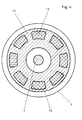
- the hub 11 can be composed of a hub body 13 and a cover 14 such that the cover 14 forms the seat for the knife 3.
- Lid 14 and hub body 13 preferably form a support device and are detachably connected to one another, preferably by at least one screw 15.
- the hub body 13 is made of a non-magnetic or non-magnetizable material such as aluminum, while the lid 14 is made of a magnetic or magnetizable material such as for electrical transformers suitable steel.
- recesses 16 are incorporated, in which permanent magnets 17 are inserted.
- eight recesses 16 are incorporated on the circumference of the hub body 13, so that up to eight permanent magnets can be placed in these recesses.
- a disc 18 covering the recesses 16 can be pushed onto the hub body 13. If the disk 18 additionally consists of a magnetic or magnetizable material, such as steel or steels suitable for electrical transformers, then the forces exerted on the upper knife 3 by the permanent magnets 17 are further increased.
- the cover 14 can consist of such steels which are common in electrical transformer construction, but such a steel can also be used which can be hardened, for example also hardened in use, so that a seat with little wear for the knife 3 results.
- This seat can consist of a shoulder 19 worked on the cover 14, so that a groove 20 for receiving and holding the upper knife 3 is formed in the fully assembled state. This groove is usually often wider than the upper knife 3, so that the upper knife 3 can adjust itself to the current cutting conditions within certain limits.
- the permanent magnets can be of a commercially available type. The effect that the permanent magnets 17 exert on the upper knife 3 occurs essentially in the direction of the geometric axis of the shaft 5 and thus also of the hub 11 and is not mechanical.
- the upper knife 3 is exposed to non-mechanical forces which dampen or even prevent the upper knife 3 from oscillating or vibrating, so that the upper knife 3 runs smoothly at very high speeds at the cutting point 8 relative to the lower knife 4.
- This processes the substrate to be processed in such a way that the processing process is of good quality.
- the machining can consist, for example, of slitting, but also, for example, of longitudinal perforations or any other machining operation. If the disc 18 ceases, there is less force acting on the upper knife 3, so that its overall effect is less than when the disc is used. Since the available space for the magnets is limited, the disk 18 thus has an increasing effect.
- electromagnets can also be used, for which purpose it is necessary to supply electrical current to these magnets in a suitable manner, for example in that electrical sliding contacts 13 are provided on the circumference of the hub body.
- this possibility requires even more effort, in particular because the hubs and the knives must remain accessible to the operator, since these knives must be replaced when they have become dull after a long period of operation.
Landscapes
- Life Sciences & Earth Sciences (AREA)
- Forests & Forestry (AREA)
- Engineering & Computer Science (AREA)
- Mechanical Engineering (AREA)
- Perforating, Stamping-Out Or Severing By Means Other Than Cutting (AREA)
- Nonmetal Cutting Devices (AREA)
- Details Of Cutting Devices (AREA)
Applications Claiming Priority (2)
| Application Number | Priority Date | Filing Date | Title |
|---|---|---|---|
| DE4014238 | 1990-05-04 | ||
| DE4014238A DE4014238A1 (de) | 1990-05-04 | 1990-05-04 | Einrichtung zum andruecken eines substratbearbeitungswerkzeuges |
Publications (2)
| Publication Number | Publication Date |
|---|---|
| EP0455041A1 true EP0455041A1 (fr) | 1991-11-06 |
| EP0455041B1 EP0455041B1 (fr) | 1993-06-16 |
Family
ID=6405654
Family Applications (1)
| Application Number | Title | Priority Date | Filing Date |
|---|---|---|---|
| EP91106029A Expired - Lifetime EP0455041B1 (fr) | 1990-05-04 | 1991-04-15 | Dispositif pour serrer un instrument de traitement de substrat |
Country Status (5)
| Country | Link |
|---|---|
| US (1) | US5188012A (fr) |
| EP (1) | EP0455041B1 (fr) |
| DE (2) | DE4014238A1 (fr) |
| ES (1) | ES2027938T3 (fr) |
| FI (1) | FI95108C (fr) |
Cited By (1)
| Publication number | Priority date | Publication date | Assignee | Title |
|---|---|---|---|---|
| WO1993020985A1 (fr) * | 1992-04-16 | 1993-10-28 | Boerbrink Stefan | Outil coupant pour operations de coupe sur materiau en planches |
Families Citing this family (4)
| Publication number | Priority date | Publication date | Assignee | Title |
|---|---|---|---|---|
| DE10034719A1 (de) * | 2000-07-17 | 2002-01-31 | Josef Froehling Gmbh Walzwerks | Längsteilschere |
| US20060037446A1 (en) * | 2004-08-18 | 2006-02-23 | Eastman Kodak Company | Angled crosscut knife |
| EP2465702B1 (fr) * | 2010-12-16 | 2015-03-25 | Neopost Technologies | Dispositif de découpe d'enveloppes |
| EP3254791B1 (fr) * | 2016-04-19 | 2022-11-09 | JDC, Inc. | Appareil de placement pour inserts de corps d'arbre |
Citations (3)
| Publication number | Priority date | Publication date | Assignee | Title |
|---|---|---|---|---|
| DE1841256U (de) * | 1961-07-03 | 1961-11-09 | Wilhelm Bilstein Dreherei | Kreismesserhalter fuer obermesser. |
| US3055249A (en) * | 1958-09-02 | 1962-09-25 | Nat Res Dev | Tape slitting apparatus |
| WO1989007206A1 (fr) * | 1988-02-04 | 1989-08-10 | Thrige Agro A/S | Joint a boulon de blocage et boulon de blocage associe |
Family Cites Families (9)
| Publication number | Priority date | Publication date | Assignee | Title |
|---|---|---|---|---|
| DE310796C (fr) * | ||||
| DE697108C (de) * | 1938-08-25 | 1940-10-05 | Jagenberg Werke Ag | Kreismesser zum Laengsschneiden von Papier-, Pappe- oder aehnlichen Werkstoffbahnen |
| US3080784A (en) * | 1959-05-02 | 1963-03-12 | Jagenberg Werke Ag | Apparatus for cutting moving webs |
| US3459086A (en) * | 1966-10-06 | 1969-08-05 | Beloit Eastern Corp | Self-sharpening slitter |
| US3682032A (en) * | 1969-06-23 | 1972-08-08 | Beloit Corp | Slitter with sharpness retention capability |
| US4274319A (en) * | 1977-06-27 | 1981-06-23 | Lenox Machine Company, Inc. | Slitter for high bulk traveling paper web material |
| US4195542A (en) * | 1978-11-24 | 1980-04-01 | Cowles Tool Company | Quick detachable magnetic spacing means for rotary slitting knives |
| DE3421331A1 (de) * | 1983-07-01 | 1985-01-17 | SMS Schloemann-Siemag AG, 4000 Düsseldorf | Kreismesserschere zum laengsbesaeumen von blechen und baendern |
| DE3726434C1 (de) * | 1987-08-08 | 1988-12-08 | Pietro Poggetti | Schere |
-
1990
- 1990-05-04 DE DE4014238A patent/DE4014238A1/de not_active Withdrawn
-
1991
- 1991-04-15 EP EP91106029A patent/EP0455041B1/fr not_active Expired - Lifetime
- 1991-04-15 DE DE9191106029T patent/DE59100150D1/de not_active Expired - Lifetime
- 1991-04-15 ES ES199191106029T patent/ES2027938T3/es not_active Expired - Lifetime
- 1991-04-26 FI FI912047A patent/FI95108C/fi not_active IP Right Cessation
- 1991-04-30 US US07/693,802 patent/US5188012A/en not_active Expired - Fee Related
Patent Citations (3)
| Publication number | Priority date | Publication date | Assignee | Title |
|---|---|---|---|---|
| US3055249A (en) * | 1958-09-02 | 1962-09-25 | Nat Res Dev | Tape slitting apparatus |
| DE1841256U (de) * | 1961-07-03 | 1961-11-09 | Wilhelm Bilstein Dreherei | Kreismesserhalter fuer obermesser. |
| WO1989007206A1 (fr) * | 1988-02-04 | 1989-08-10 | Thrige Agro A/S | Joint a boulon de blocage et boulon de blocage associe |
Cited By (2)
| Publication number | Priority date | Publication date | Assignee | Title |
|---|---|---|---|---|
| WO1993020985A1 (fr) * | 1992-04-16 | 1993-10-28 | Boerbrink Stefan | Outil coupant pour operations de coupe sur materiau en planches |
| US5659961A (en) * | 1992-04-16 | 1997-08-26 | Gyproc Group Ab | Cutting tool to perform cutting operations on board material |
Also Published As
| Publication number | Publication date |
|---|---|
| ES2027938T3 (es) | 1993-12-01 |
| DE59100150D1 (de) | 1993-07-22 |
| US5188012A (en) | 1993-02-23 |
| FI95108B (fi) | 1995-09-15 |
| DE4014238A1 (de) | 1991-11-07 |
| FI912047L (fi) | 1991-11-05 |
| ES2027938T1 (es) | 1992-07-01 |
| FI95108C (fi) | 1995-12-27 |
| EP0455041B1 (fr) | 1993-06-16 |
| FI912047A0 (fi) | 1991-04-26 |
Similar Documents
| Publication | Publication Date | Title |
|---|---|---|
| DE2912458C2 (fr) | ||
| DE3623035C1 (de) | Verfahren und Vorrichtung zum Herstellen eines eine scharfe Schneidkante aufweisenden Stanzwerkzeugs | |
| DE4211187A1 (de) | Zylinder zum Bearbeiten | |
| EP0455041B1 (fr) | Dispositif pour serrer un instrument de traitement de substrat | |
| DE2643655A1 (de) | Rohrschneidevorrichtung | |
| DE3423674C1 (de) | Vorrichtung zum mehrachsigen Formschneiden im Quetschschnitt von weichen Materialien, wie Papier, Kunststoff, Gummi oder dergleichen | |
| DE2741908A1 (de) | Schneidbreiten-aenderungsvorrichtung an bahnlaengsschneidmaschinen | |
| DE3119602A1 (de) | Vorrichtung zum einstanzen eines loches in eine papierbahn | |
| DE2628728C2 (de) | Schneidvorrichtung mit rotierenden Flügelmessern zur Herstellung von Formschnitten in die Ränder bewegter Werkstoffbahnen | |
| DE69800951T2 (de) | Messer und Messerhalter zur Verwendung in einem Verarbeitungssystem für blattförmiges Material | |
| EP0507916B1 (fr) | Dispositif de support | |
| DE60021885T2 (de) | Kraftverstellbarer drehender apparat zum bearbeiten von bahnen | |
| DD140229A5 (de) | Vorrichtung zum boerdeln von kugelschreiberspitzen | |
| DE9005047U1 (de) | Einrichtung zum Andrücken eines Substratbearbeitungswerkzeuges | |
| DE1234511B (de) | Vorrichtung zum Abschneiden einer Papierbahn | |
| DE4201242A1 (de) | Vorrichtung zum andruecken eines bearbeitungswerkzeuges | |
| DE2706510C2 (de) | Stabeisenschere | |
| EP0714720B1 (fr) | Machine pour estamper et couper | |
| EP1174229A2 (fr) | Machine de découpage longitudinal | |
| DE2542635A1 (de) | Vorrichtung zum querschneiden einer laenglichen materialrolle | |
| DE69615779T2 (de) | Rotationsschneidvorrichtung | |
| EP3383779B1 (fr) | Support de lame de rasoir à réglage d'angle pour machine de coupe et d'enroulement | |
| DE3526213C2 (fr) | ||
| DE9200561U1 (de) | Vorrichtung zum Andrücken eines Bearbeitungswerkzeuges | |
| DE3526248A1 (de) | Einrichtung zum rotierenden stanzen von bahnen |
Legal Events
| Date | Code | Title | Description |
|---|---|---|---|
| PUAI | Public reference made under article 153(3) epc to a published international application that has entered the european phase |
Free format text: ORIGINAL CODE: 0009012 |
|
| 17P | Request for examination filed |
Effective date: 19910826 |
|
| AK | Designated contracting states |
Kind code of ref document: A1 Designated state(s): BE CH DE ES FR GB IT LI NL SE |
|
| ITCL | It: translation for ep claims filed |
Representative=s name: BARZANO' E ZANARDO MILANO S.P.A. |
|
| 17Q | First examination report despatched |
Effective date: 19911217 |
|
| TCNL | Nl: translation of patent claims filed | ||
| GBC | Gb: translation of claims filed (gb section 78(7)/1977) | ||
| EL | Fr: translation of claims filed | ||
| GRAA | (expected) grant |
Free format text: ORIGINAL CODE: 0009210 |
|
| ITF | It: translation for a ep patent filed | ||
| AK | Designated contracting states |
Kind code of ref document: B1 Designated state(s): BE CH DE ES FR GB IT LI NL SE |
|
| REF | Corresponds to: |
Ref document number: 59100150 Country of ref document: DE Date of ref document: 19930722 |
|
| ET | Fr: translation filed | ||
| GBT | Gb: translation of ep patent filed (gb section 77(6)(a)/1977) |
Effective date: 19930629 |
|
| REG | Reference to a national code |
Ref country code: ES Ref legal event code: FG2A Ref document number: 2027938 Country of ref document: ES Kind code of ref document: T3 |
|
| PLBE | No opposition filed within time limit |
Free format text: ORIGINAL CODE: 0009261 |
|
| STAA | Information on the status of an ep patent application or granted ep patent |
Free format text: STATUS: NO OPPOSITION FILED WITHIN TIME LIMIT |
|
| 26N | No opposition filed | ||
| EAL | Se: european patent in force in sweden |
Ref document number: 91106029.1 |
|
| PGFP | Annual fee paid to national office [announced via postgrant information from national office to epo] |
Ref country code: ES Payment date: 19950404 Year of fee payment: 5 |
|
| PGFP | Annual fee paid to national office [announced via postgrant information from national office to epo] |
Ref country code: FR Payment date: 19950405 Year of fee payment: 5 |
|
| PGFP | Annual fee paid to national office [announced via postgrant information from national office to epo] |
Ref country code: GB Payment date: 19950406 Year of fee payment: 5 |
|
| PGFP | Annual fee paid to national office [announced via postgrant information from national office to epo] |
Ref country code: BE Payment date: 19950412 Year of fee payment: 5 |
|
| PGFP | Annual fee paid to national office [announced via postgrant information from national office to epo] |
Ref country code: SE Payment date: 19950418 Year of fee payment: 5 |
|
| PGFP | Annual fee paid to national office [announced via postgrant information from national office to epo] |
Ref country code: NL Payment date: 19950430 Year of fee payment: 5 |
|
| PGFP | Annual fee paid to national office [announced via postgrant information from national office to epo] |
Ref country code: CH Payment date: 19950613 Year of fee payment: 5 |
|
| PGFP | Annual fee paid to national office [announced via postgrant information from national office to epo] |
Ref country code: DE Payment date: 19960326 Year of fee payment: 6 |
|
| PG25 | Lapsed in a contracting state [announced via postgrant information from national office to epo] |
Ref country code: GB Effective date: 19960415 |
|
| PG25 | Lapsed in a contracting state [announced via postgrant information from national office to epo] |
Ref country code: SE Effective date: 19960416 Ref country code: ES Free format text: LAPSE BECAUSE OF EXPIRATION OF PROTECTION Effective date: 19960416 |
|
| PG25 | Lapsed in a contracting state [announced via postgrant information from national office to epo] |
Ref country code: LI Effective date: 19960430 Ref country code: CH Effective date: 19960430 Ref country code: BE Effective date: 19960430 |
|
| BERE | Be: lapsed |
Owner name: MASCHINENFABRIK GOEBEL G.M.B.H. Effective date: 19960430 |
|
| PG25 | Lapsed in a contracting state [announced via postgrant information from national office to epo] |
Ref country code: NL Effective date: 19961101 |
|
| GBPC | Gb: european patent ceased through non-payment of renewal fee |
Effective date: 19960415 |
|
| REG | Reference to a national code |
Ref country code: CH Ref legal event code: PL |
|
| PG25 | Lapsed in a contracting state [announced via postgrant information from national office to epo] |
Ref country code: FR Effective date: 19961227 |
|
| NLV4 | Nl: lapsed or anulled due to non-payment of the annual fee |
Effective date: 19961101 |
|
| EUG | Se: european patent has lapsed |
Ref document number: 91106029.1 |
|
| REG | Reference to a national code |
Ref country code: FR Ref legal event code: ST |
|
| PG25 | Lapsed in a contracting state [announced via postgrant information from national office to epo] |
Ref country code: DE Effective date: 19970425 |
|
| REG | Reference to a national code |
Ref country code: ES Ref legal event code: FD2A Effective date: 19990601 |
|
| PG25 | Lapsed in a contracting state [announced via postgrant information from national office to epo] |
Ref country code: IT Free format text: LAPSE BECAUSE OF NON-PAYMENT OF DUE FEES Effective date: 20050415 |