EP0455047A2 - Dispositif pour le centrage horizontal et serrage autobloquant d'outils de moulage - Google Patents
Dispositif pour le centrage horizontal et serrage autobloquant d'outils de moulage Download PDFInfo
- Publication number
- EP0455047A2 EP0455047A2 EP91106138A EP91106138A EP0455047A2 EP 0455047 A2 EP0455047 A2 EP 0455047A2 EP 91106138 A EP91106138 A EP 91106138A EP 91106138 A EP91106138 A EP 91106138A EP 0455047 A2 EP0455047 A2 EP 0455047A2
- Authority
- EP
- European Patent Office
- Prior art keywords
- clamping
- tool
- molds
- plates
- wedges
- Prior art date
- Legal status (The legal status is an assumption and is not a legal conclusion. Google has not performed a legal analysis and makes no representation as to the accuracy of the status listed.)
- Withdrawn
Links
Images



Classifications
-
- B—PERFORMING OPERATIONS; TRANSPORTING
- B29—WORKING OF PLASTICS; WORKING OF SUBSTANCES IN A PLASTIC STATE IN GENERAL
- B29C—SHAPING OR JOINING OF PLASTICS; SHAPING OF MATERIAL IN A PLASTIC STATE, NOT OTHERWISE PROVIDED FOR; AFTER-TREATMENT OF THE SHAPED PRODUCTS, e.g. REPAIRING
- B29C45/00—Injection moulding, i.e. forcing the required volume of moulding material through a nozzle into a closed mould; Apparatus therefor
- B29C45/17—Component parts, details or accessories; Auxiliary operations
- B29C45/1742—Mounting of moulds; Mould supports
Definitions
- the invention relates to a device for horizontal centering and self-locking clamping of molds, which are introduced horizontally or vertically in the horizontal or vertical working position in the tool space of an injection molding machine, which is limited by a fixed and a movable platen.
- the columns are connected or connected to one another by means of columns mounted in the tool clamping plates, and clamping wedges which are moved by drives and which are embedded in the tool clamping plates, are detachably attached to the mold clamping plates.
- a slightly protruding centering ring is attached to the molding tool in practice, or fixed stops are arranged in the tool room.
- the disadvantage here is that damage to the centering ring or to the fixed stops cannot be avoided when carrying out tool movements in the tool store or in the tool space of the injection molding machine.
- the aim of the invention is to provide a technically, economically cost-effective and functionally reliable centering device for flexible production systems in injection molding machines, as well as a self-locking clamping device for vertical and horizontal tool changes, which retrofits the centering and clamping elements when changing the insertion direction or when changing does not require the working position of the mold.
- the object of the invention is to develop a centering device and self-locking clamping device for changing tools in injection molding machines, in which the molds in the horizontal and vertical working position and in the horizontal or vertical insertion direction on the contacting clamping surfaces between the mold and Tool clamping plate, have no outstanding centering or clamping elements during the tool change.
- the object is achieved in that at least four clamping wedges are embedded flush with the clamping surface at an inclination angle ⁇ in the tool clamping plates parallel to two opposite outer edges in the grid dimension of the Euromap drilling pattern.
- At least two splines are arranged on the clamping surfaces of the molds or the adapter plates at the same angle of inclination parallel to each outer edge of the tool clamping plates so that the clamping wedges, which can be extended by drives, can be inserted into the splines.
- the clamping wedges and the drives are integrated in cuboid-shaped components which are fastened therein parallel to the outer edges of the tool clamping plates, flush with the clamping surface.
- the wedge clamping surfaces on the clamping wedges are inclined at an angle of inclination ⁇ of approx. 5 ° to the direction of displacement.
- the wedge clamping surfaces of the clamping wedges and the keyways are preferably inclined at an angle of inclination ⁇ , which is in the range of approx. 45 ° , to the tool clamping plates.
- the advantages of the solution according to the invention are that the molds and the platen have no outstanding centering or clamping elements during the tool change. This makes it possible, depending on the most favorable technological conditions, to carry out the tool change for molds in a horizontal or vertical working position and in a horizontal or vertical insertion direction.
- the arrangement of the keyways in the molds or adapter plates parallel to the outer edges of the platen also makes it possible that when changing the working position or the direction of insertion as part of the tool change it is not necessary to retool the clamping wedges integrated in the platen.
- the clamping device according to the invention ensures horizontal self-centering from a pre-centered position, which is made possible by the spatial arrangement of the clamping wedges and their centering force components.
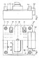
- a tool platen 1 is shown in the front and side view, which can be connected or connected to a second tool platen, not shown, by columns 2.
- a mold 3 which is only shown in half section, is attached.
- the molding tool 3 has a rectangular contour, protrudes in length beyond the vertical distance that the columns 2 have from one another, and was introduced horizontally into the tool space of the injection molding machine in a horizontal working position.
- the adapter plate 11, on which the molding tool 3 is fastened, is based on a height-adjustable support 12 or, which is known per se and is not explained in more detail from a corresponding pedestal, which is used to fix the mold horizontally.
- At least four clamping wedges 4 are embedded at an angle of inclination ⁇ in each tool clamping plate 1 parallel to two opposite outer edges 5 in the grid dimension of the Euromap drilling pattern 6, flush with the clamping surface 7.
- a preferred embodiment is shown in FIGS. 1 and 6, in which the clamping wedges 4 and the associated drives 10 are integrated in cuboidal blocks 9, which in turn are embedded in the tool mounting plate 1 flush with the mounting surface 7.
- On the clamping surfaces 7 of the molds 3 or the adapter plates 11, at least two splines 8 are arranged at the same angle of inclination ⁇ parallel to each outer edge of the platen 1 so that the clamping wedges 4 which can be extended by the drives 10 can be inserted into the splines 8.
- FIG. 3 in an enlarged sectional view through a building block, the arrangement of the building block 9 with clamping wedge 4 and drive 10 in the tool mounting plate 1 and the mold tool 3, or its adapter plate 11, resting on the tool mounting plate can be seen. It is clearly visible that the block 9 and the clamping wedge 4, which is still in the retracted position, are flush with the clamping surface 7 of the tool mounting plate 1 and do not protrude beyond it, which means that the molding tool 3 can be inserted in any working position and direction of insertion without problems Tool room is possible. In the broken line, the clamping wedge 4 was extended into the keyway 8 in the adapter plate 11 or in the mold 3 with the aid of the drive 10, which is preferably designed as a hydraulic working cylinder 13.
- the outer end of the piston rod 14 of the working cylinder 13 is simultaneously designed as a clamping wedge 4.
- the position of the clamping wedge 4 relative to the keyway 8 is fixed by an anti-rotation device 15 which is arranged in the module 9 and engages in a guide groove 16 which is located in the piston rod 14.
- the block 9 is by fastening screws, not shown, to the platen releasably connected.
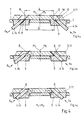
- FIG. 4A shows the state in which the molding tool 3 or the adapter plate 11 is in a pre-centered position with respect to the tool mounting plate 1.
- This pre-centered position makes it necessary that the inside of the splines 8 of the mold 3 or the adapter plate 11, which come to rest on the clamping surface 7 and are characterized by the distance A, must not protrude beyond the spline surfaces 17 of the clamping wedges 4. It can be seen that the center M1 of the platen 1 does not match the center M3 of the mold 3.
- Another condition for ensuring the centering and clamping process is that the inner distance B of the keyways 18 on the mounting surface 7 of the tool mounting plate 1 or the blocks 9 must be smaller than the distance A.
- the clamping wedges 4 are acted upon by a driving force FK through the piston rods 14 of the working cylinders 13.
- the moving out of the piston rods 14 from the platen 1 is shown in FIG. 4B, the right piston rod 14 with the clamping wedge 4 extending directly into its end position without the wedge clamping surface 17 coming into contact.
- the left piston rod 14 comes into contact with the clamping wedge 4 on the keyway of the molding tool 3 or the adapter plate 11.
- a transverse force FZ acts on the mold 3, by means of which, as can be seen from FIG. 4C, the mold 3 or the adapter plate 11 is centered horizontally when the piston rod 14 is moved out further.
- the clamping force FS is built up, which is directed perpendicularly against the tool clamping plate 1 and thus approximately opposite to the driving force FK. Due to the transverse forces FZ, the mold 3 or the adapter plate 11 can no longer move, since their effect is canceled. In this position, the center M1 of the platen 1 coincides with the center M3 of the mold 3 match.
- the positioning accuracy when changing tools is dependent on the difference between dimension A and dimension B.
- angle of inclination of the keyways 18 for receiving the clamping wedges 4, in the tool clamping plates 1 or in the building blocks 9, in order to ensure self-locking for the clamping process must differ by the size of the angle of inclination ⁇ compared to the angle of inclination ⁇ .
- FIGS. 1 and 2 show the same half of the molding tool 3 with an elongated rectangular contour in half section.
- the molding tool 3 was not introduced into the tool space in a horizontal but in a vertical working position and fastened vertically to the mold platen 1 of the injection molding machine.
- the height-adjustable support 12 must be pre-positioned on the vertical installation height of the mold 3 before the tool change.
- the position of the building blocks 9 integrated in the mold clamping plate 1 with the clamping wedges 4 and the associated drives has remained unchanged.
- the extendable clamping wedges 4 were not inserted into the keyways 8, which are located on the short side of the adapter plate 11, but into the keyways 8, which are located on the long side of the adapter plate 11.
- the double number of keyways 8 is available in the corresponding pitch of the Euromap drilling pattern corresponding to the clamping wedges.
- This double number results inevitably from the parallel arrangement of at least two splines 8 on the mounting surfaces 7 of the molds 3 or the adapter plates 11 parallel to each outer edge 5 of the mounting plate. The result of this is that only half the number of keyways 8 present becomes functionally effective for the clamping process and the non-used keyways 8 become functionally effective when the molding tool 3 is installed in a position changed by 90 ° .
- the self-locking of the clamping connection produced occurs when the wedge clamping surfaces 17 of the clamping wedges 4 are inclined by approximately 5 ° to the direction of displacement. Furthermore, it is advantageous if the wedge clamping surfaces 17 of the clamping wedges 4 and the splines 8 are preferably inclined at an angle of inclination ⁇ , which should be in the range of 45 ° , because this results in a favorable force distribution for the centering and clamping process, as shown in Figure 4C and Figure 5 can be seen.
Landscapes
- Engineering & Computer Science (AREA)
- Manufacturing & Machinery (AREA)
- Mechanical Engineering (AREA)
- Moulds For Moulding Plastics Or The Like (AREA)
Applications Claiming Priority (2)
| Application Number | Priority Date | Filing Date | Title |
|---|---|---|---|
| DD90340260A DD293988A5 (de) | 1990-05-02 | 1990-05-02 | Einrichtung zum horizontalen zentrieren und selbsthemmenden spannen von formwerkzeugen |
| DD340260 | 1990-05-02 |
Publications (2)
| Publication Number | Publication Date |
|---|---|
| EP0455047A2 true EP0455047A2 (fr) | 1991-11-06 |
| EP0455047A3 EP0455047A3 (en) | 1992-05-06 |
Family
ID=5618194
Family Applications (1)
| Application Number | Title | Priority Date | Filing Date |
|---|---|---|---|
| EP19910106138 Withdrawn EP0455047A3 (en) | 1990-05-02 | 1991-04-17 | Apparatus for horizontal centering and self-locking clamping of mould tools |
Country Status (3)
| Country | Link |
|---|---|
| EP (1) | EP0455047A3 (fr) |
| JP (1) | JPH04229218A (fr) |
| DD (1) | DD293988A5 (fr) |
Cited By (1)
| Publication number | Priority date | Publication date | Assignee | Title |
|---|---|---|---|---|
| CN114161179A (zh) * | 2021-12-27 | 2022-03-11 | 上海楚峰机电有限公司 | 一种楔形结构、定向驱动结构和固定结构 |
Family Cites Families (3)
| Publication number | Priority date | Publication date | Assignee | Title |
|---|---|---|---|---|
| DE3213209C2 (de) * | 1981-12-11 | 1984-04-12 | Karl 7298 Loßburg Hehl | Formenspannvorrichtung an einer Formschließeinheit |
| DE3215567C2 (de) * | 1982-04-26 | 1996-07-11 | Battenfeld Gmbh | Schnellwechsel- und/oder Spannvorrichtung für die Formwerkzeuge von Druck- oder Spritzgießmaschinen |
| FR2595291A1 (fr) * | 1986-03-07 | 1987-09-11 | Picard Claude | Dispositif hydraulique de bridage pour la fixation demontable des outils de conformation sur les presses a mouler |
-
1990
- 1990-05-02 DD DD90340260A patent/DD293988A5/de not_active IP Right Cessation
-
1991
- 1991-04-17 EP EP19910106138 patent/EP0455047A3/de not_active Withdrawn
- 1991-04-23 JP JP3119250A patent/JPH04229218A/ja active Pending
Cited By (1)
| Publication number | Priority date | Publication date | Assignee | Title |
|---|---|---|---|---|
| CN114161179A (zh) * | 2021-12-27 | 2022-03-11 | 上海楚峰机电有限公司 | 一种楔形结构、定向驱动结构和固定结构 |
Also Published As
| Publication number | Publication date |
|---|---|
| JPH04229218A (ja) | 1992-08-18 |
| EP0455047A3 (en) | 1992-05-06 |
| DD293988A5 (de) | 1991-09-19 |
Similar Documents
| Publication | Publication Date | Title |
|---|---|---|
| EP0092685B1 (fr) | Dispositif de changement rapide et/ou serrage de moules pour machines à injection | |
| EP0092686B1 (fr) | Dispositif de changement rapide et/ou serrage de moules pour machines à injection | |
| EP1197319B2 (fr) | Entraînement par coin | |
| EP3572198B1 (fr) | Coffrage central pour un système de coffrage destiné à bétonner un corps de cloche | |
| EP0222290B1 (fr) | Dispositif de soudage | |
| EP2910687B1 (fr) | Dispositif et procédé de fabrication d'un tunnel présentant plusieurs tronçons de tunnel | |
| EP0143878B1 (fr) | Dispositif de fixation pour moules | |
| DE68923682T2 (de) | Klemmvorrichtung des Oberteils einer Metallform einer Reifenvulkanisiermaschine. | |
| EP0002814B2 (fr) | Coffrage pour béton formé de panneaux assemblés par clavettage | |
| DE3871595T2 (de) | System fuer das schnelle aufspannen von formen in einer horizontalen presse zum spritzgiessen von kunststoff. | |
| DE10139080A1 (de) | Montagelehre für Linearführungsschienen und Verfahren zur Montage von Linearführungsschienen | |
| DE3687839T2 (de) | Vertikale formspritzmaschine. | |
| AT394516B (de) | Einrichtung zum kuppeln von energieanschluessen beim wechseln und spannen von formwerkzeugen | |
| EP0455047A2 (fr) | Dispositif pour le centrage horizontal et serrage autobloquant d'outils de moulage | |
| DE2446768C3 (de) | Vorrichtung zum Einrütteln von Dübeln in Straßendecken aus Beton | |
| DE3140837C2 (de) | Druckgießmaschine | |
| DE69410618T2 (de) | Mechanische Betonstahlverbindung, Vorrichtung zur Montage derselben und Verfahren zur Befestigung von Betonstählen | |
| DE69000859T2 (de) | Vorrichtung zum aufstellen und stuetzen eines inneren schalungspaneels. | |
| DE102018121564A1 (de) | Vorrichtung zum Herstellen von Steinformlingen für Mauerwerksteine, insbesondere Kalksandsteine, mit verstellbaren Formwänden | |
| DE3002039A1 (de) | Stehende hydraulische gesenkpresse | |
| EP0144007A2 (fr) | Dispositif de blindage | |
| WO2022200522A1 (fr) | Élément de coffrage de cadre pour un système de coffrage mural, pièce d'insertion pour un élément de coffrage de cadre, système de coffrage mural et procédé de fabrication d'un système de coffrage | |
| DE69306423T2 (de) | Vorrichtung zum Ausrichten und Zusammenbringen von Schaltafeln | |
| DE2607212A1 (de) | Giessform fuer plattenartige elemente | |
| DE4329401C2 (de) | Anlage für die Durchführung eines Arbeitsverfahrens zum Einbauen und Ausbauen eines aus Unterform und Oberform bestehenden, mit komplementären Wellflächen versehenen Formensatzes, bei einer Plattenpresse für das Pressen von Preßgutmatten im Zuge der Herstellung von Faserzement-Wellplatten |
Legal Events
| Date | Code | Title | Description |
|---|---|---|---|
| PUAI | Public reference made under article 153(3) epc to a published international application that has entered the european phase |
Free format text: ORIGINAL CODE: 0009012 |
|
| AK | Designated contracting states |
Kind code of ref document: A2 Designated state(s): AT CH DE FR GB IT LI |
|
| RAP1 | Party data changed (applicant data changed or rights of an application transferred) |
Owner name: HEMSCHEIDT MASCHINENTECHNIK SCHWERIN GMBH & CO. |
|
| PUAL | Search report despatched |
Free format text: ORIGINAL CODE: 0009013 |
|
| AK | Designated contracting states |
Kind code of ref document: A3 Designated state(s): AT CH DE FR GB IT LI |
|
| 17P | Request for examination filed |
Effective date: 19920908 |
|
| 17Q | First examination report despatched |
Effective date: 19940506 |
|
| STAA | Information on the status of an ep patent application or granted ep patent |
Free format text: STATUS: THE APPLICATION IS DEEMED TO BE WITHDRAWN |
|
| 18D | Application deemed to be withdrawn |
Effective date: 19941213 |