EP0455075A1 - Gerät zum Unschädlichmachen von KanÀ¼len - Google Patents
Gerät zum Unschädlichmachen von KanÀ¼len Download PDFInfo
- Publication number
- EP0455075A1 EP0455075A1 EP91106374A EP91106374A EP0455075A1 EP 0455075 A1 EP0455075 A1 EP 0455075A1 EP 91106374 A EP91106374 A EP 91106374A EP 91106374 A EP91106374 A EP 91106374A EP 0455075 A1 EP0455075 A1 EP 0455075A1
- Authority
- EP
- European Patent Office
- Prior art keywords
- electrode
- cannula
- metal tube
- insertion opening
- housing
- Prior art date
- Legal status (The legal status is an assumption and is not a legal conclusion. Google has not performed a legal analysis and makes no representation as to the accuracy of the status listed.)
- Granted
Links
- 238000003780 insertion Methods 0.000 claims abstract description 46
- 230000037431 insertion Effects 0.000 claims abstract description 46
- 239000002184 metal Substances 0.000 claims abstract description 43
- 238000009877 rendering Methods 0.000 claims abstract description 5
- 241001631457 Cannula Species 0.000 claims description 9
- 239000007787 solid Substances 0.000 claims description 3
- 208000015181 infectious disease Diseases 0.000 description 4
- 239000007788 liquid Substances 0.000 description 4
- 208000027418 Wounds and injury Diseases 0.000 description 2
- 230000006378 damage Effects 0.000 description 2
- 208000014674 injury Diseases 0.000 description 2
- 239000011505 plaster Substances 0.000 description 2
- 238000005452 bending Methods 0.000 description 1
- 230000015572 biosynthetic process Effects 0.000 description 1
- 238000010586 diagram Methods 0.000 description 1
- 239000010791 domestic waste Substances 0.000 description 1
- 239000000155 melt Substances 0.000 description 1
- 238000010309 melting process Methods 0.000 description 1
- 238000000034 method Methods 0.000 description 1
Images


Classifications
-
- A—HUMAN NECESSITIES
- A61—MEDICAL OR VETERINARY SCIENCE; HYGIENE
- A61M—DEVICES FOR INTRODUCING MEDIA INTO, OR ONTO, THE BODY; DEVICES FOR TRANSDUCING BODY MEDIA OR FOR TAKING MEDIA FROM THE BODY; DEVICES FOR PRODUCING OR ENDING SLEEP OR STUPOR
- A61M5/00—Devices for bringing media into the body in a subcutaneous, intra-vascular or intramuscular way; Accessories therefor, e.g. filling or cleaning devices, arm-rests
- A61M5/178—Syringes
- A61M5/31—Details
- A61M5/32—Needles; Details of needles pertaining to their connection with syringe or hub; Accessories for bringing the needle into, or holding the needle on, the body; Devices for protection of needles
- A61M5/3205—Apparatus for removing or disposing of used needles or syringes, e.g. containers; Means for protection against accidental injuries from used needles
- A61M5/3278—Apparatus for destroying used needles or syringes
- A61M2005/3283—Apparatus for destroying used needles or syringes using electric current between electrodes
Definitions
- the invention relates to a device for rendering single needles of a syringe harmless, having a housing with an insertion opening for the metal tube of the cannula and an electrode arrangement arranged below the insertion opening and comprising two electrodes, via which a circuit for rendering the metal tube of the cannula unusable
- the cannula can be closed, the insertion opening limiting the insertion movement by a stop for a head of the cannula.
- syringes are primarily used that are intended for single use only. They consist of a plastic syringe body onto which the cannula consisting of a metal tube and a plastic body forming a cannula head is pushed.
- the cannula or its metal tube In order to prevent repeated use of such cannulas taking place, which entails the risk of infection, it is known to manually bend the cannula or its metal tube from the straight state and to deform it into a curved shape, so that without further ado it can be seen that the cannula has already been used once. In this state, the cannulas often end up in household waste.
- a device of the type mentioned in which two resiliently mounted electrodes which are not in contact with one another are arranged below the insertion opening and can be connected through the metal tube of the cannula, so that a current flows through the metal tube of the cannula.
- the insertion opening is designed so that the cannula, including its plastic head, can be inserted into the interior of the device.
- a lateral elongated extension of the insertion opening allows the head to reach behind during the lateral movement in the direction of the elongated extension
- an oblique guide on the underside of the elongated extension ensures that the cannula is separated from the syringe body, so that the complete is in a drawer in the device Cannula with the deformed metal tube falls in and the user only has the syringe body open at the bottom in his hand.
- the invention has for its object to improve a device of the type mentioned in terms of handling and functional reliability and to further reduce the risk of injury and infection.
- the insertion opening is circular and only allows the insertion of the metal tube in its longitudinal direction that immediately below the insertion opening a first electrode is arranged with a through opening for the metal tube and that a second electrode is arranged such that the tip of the metal tube strikes the second electrode after passing through the passage opening of the first electrode.
- the cannula is inserted into the insertion opening of the device only in its longitudinal direction and largely melted.
- the rest of the metal tube remaining has a melted, ie. H. no longer sharp and closed end.
- chip-like or drop-like cannula parts emerge from the metal tube.
- the formation of the first electrode, which is provided immediately below the insertion opening, with a through-opening for the metal tube achieves a reliable current flow through the metal tube, which strikes the tip of the second electrode and melts there.
- the second electrode is preferably provided at the point of impact with a sliding surface which is oblique to the longitudinal direction of the metal tube and is designed as a solid, stationary metal block. This ensures a high level of functional reliability.
- the circular design of the insertion opening which limits the insertion movement of the cannula, preferably by means of a stop for the head of the cannula, means that the cannula is not separated from the syringe body on the device.
- the molten and closed end of the molten cannula can remain on the syringe body and can be disposed of together with it.
- the closed cannula forms, together with the syringe body, a closed system, so that any infected liquid remains safely enclosed, since pulling out the syringe plunger in the closed system would create a negative pressure and is therefore practically impossible. Any infected liquid on the rest of the metal tube is removed by the Current flow through the metal tube disinfected, the first electrode arranged immediately below the insertion opening ensures that practically the entire metal tube is covered by the current flow.
- the first electrode is formed at least in two parts, the two parts of the first electrode forming the passage opening between them.
- the two parts can be moved relative to one another against the restoring force of a spring to enlarge the passage opening.
- the passage opening expediently has a smaller diameter than conventional metal tubes of cannulas.
- the relative movement of the two parts of the first electrode to one another can be achieved in a simple structural embodiment in that one part of the first electrode is pivotably mounted relative to the other part.
- the insertion opening is expediently formed by a filling funnel, which can also serve as a stop for the cannula head.
- the manageability of the device according to the invention is further increased in that the electrodes can be connected to a DC battery arranged in the housing.
- This can be designed as a rechargeable battery.
- a switch for readiness for operation can be arranged in the circuit, a lamp for indicating readiness for operation being expediently provided in a parallel circuit.
- the switch can be actuated arbitrarily and can be designed as an on / off switch. Only when it is closed is it ready for operation and disposable cannulas can be disposed of. In the open position of the Switch is interrupted.
- the switch is expediently arranged in the part of the circuit which connects the anode to the DC battery.
- a lamp can be provided to indicate the operational readiness. This lamp then lights when the switch is on.
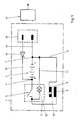
- FIG. 1 the housing 1 of the device is indicated by a dash-dotted line and otherwise the schematic circuit is shown.
- a DC battery 2 is housed in the housing, the positive pole 3 of which is connected to a switch 4.
- a line 5 leads from the switch 4 to an anode 6.
- the negative pole 7 of the direct current battery 2 is connected via line 8 to a cathode 9, which is formed in two parts, a passage opening 10 being formed between the two parts.
- a lamp 12 is arranged in a branch 11 of the circuit bridging the direct current battery 2 and the switch 4. As can be seen, the lamp 12 only burns when the switch 4 is closed.
- a line 13 leads from the positive pole 3 via a discharge protection diode 14 to a plug or socket 15.
- a corresponding line 16 leads from the negative pole 7 to the plug 15, to which a conventional charger 17, which can be connected to a socket, can be connected.
- Figure 2 shows a plan view of the device with its housing 1, which is expediently formed in several parts and has an upwardly closing housing cover 18, on the one hand an insertion funnel 19 and on the other hand a carrying handle 20 for the device.
- the design and arrangement of the insertion funnel 19 predefine an insertion direction 21 which, for example, is directed vertically from top to bottom when the device is on a table.
- FIG. 4 shows a top view or a view of the device from above with the housing cover 18 removed.
- the arrangement of the direct current battery 2 can be seen.
- the anode 6 is not shown in FIG. 4.
- FIG. 5 illustrates the mode of operation.
- the insertion funnel 19 is screwed into the housing cover 18 of the housing by means of a thread. It has a funnel-shaped shape, the smallest diameter of which is still larger than the outer diameter of the metal tube 27 of the cannula 28.
- the arrangement of the insertion funnel 19 defines the insertion direction 21 with which the cannula 28 is lowered up to its head through the insertion funnel 19 into the interior of the housing 1 of the device.
- 5 shows the two parts 23 and 24 of the cathode 9 and the passage gap 10 thus formed, which is smaller than the outer diameter of the metal tube 27 of the cannula 28.
- the pivotable part 24 of the cathode 9 can deflect according to arrow 25 (FIG.
- the passage opening 10 has a size sufficient for the metal tube 27 of the cannula 28 to pass through. If, when switch 4 is closed, a cannula 28 is inserted into the device in the manner described in the direction of insertion 21, the tip of the metal tube 27 reaches the anode 6, which is insulated as a solid metal block in the housing 1 and is connected to the direct current battery 2 via the line 5 connected is.
- the anode 6 is arranged obliquely to the insertion device 21 or has an oblique sliding surface 30, so that the circuit between the cathode 9 and the anode 6 is closed when the tip of the metal tube 27 strikes.
- This part of the metal tube 27 which produces the connection is flowed through by a current of approximately 100 A and, as a result of its thin walls, is strongly heated and melted. Melted cannula parts 31 are formed, which fall down into the drawer 26 arranged below and are collected there. A ball catch 32 secures the drawer 26 in the pushed-in position, but on the other hand allows the drawer 26 to be emptied the cannula 28 takes place continuously until the insertion process by the Placing the plastic head on the insertion funnel 19 is ended.
- the dimensioning is such that the part of the metal tube 27 which remains with a melted end also comes under sufficient heat so that the risk of infection in this regard is eliminated.
Landscapes
- Health & Medical Sciences (AREA)
- Engineering & Computer Science (AREA)
- Life Sciences & Earth Sciences (AREA)
- Animal Behavior & Ethology (AREA)
- Anesthesiology (AREA)
- Biomedical Technology (AREA)
- Heart & Thoracic Surgery (AREA)
- Hematology (AREA)
- Environmental & Geological Engineering (AREA)
- Vascular Medicine (AREA)
- General Health & Medical Sciences (AREA)
- Public Health (AREA)
- Veterinary Medicine (AREA)
- Accommodation For Nursing Or Treatment Tables (AREA)
- Infusion, Injection, And Reservoir Apparatuses (AREA)
- Endoscopes (AREA)
- Surgical Instruments (AREA)
Abstract
Description
- Die Erfindung betrifft ein Gerät zum Unschädlichmachen von zum einmaligen Gebrauch bestimmten Kanülen einer Spritze, mit einem Gehäuse mit einer Einführöffnung für das Metallrohr der Kanüle und einer unterhalb der Einführöffnung angeordneten Elektrodenanordnung aus zwei Elektroden, über die mit dem Metallrohr der Kanüle ein Stromkreis zum Unbrauchbarmachen der Kanüle schließbar ist, wobei die Einführöffnung die Einführbewegung durch einen Anschlag für einen Kopf der Kanüle begrenzt.
- Aus Gründen der Infektionsgefahr werden überwiegend Spritzen verwendet, die nur zum einmaligen Gebrauch bestimmt sind. Sie bestehen aus einem Kunststoff-Spritzenkörper, auf den die aus einem Metallrohr und einem einen Kanülenkopf bildenden Kunststoffkörper bestehende Kanüle aufgeschoben wird. Um zu verhindern, daß ein mehrfacher Gebrauch solcher Kanülen stattfindet, der die Gefahr von Infektionen mit sich bringt, ist es bekannt, die Kanüle bzw. ihr Metallrohr aus dem geraden Zustand manuell zu verbiegen und in eine gekrümmte Gestalt zu verformen, so daß ohne weiteres erkennbar ist, daß die Kanüle bereits einmal benutzt wurde. Die Kanülen gelangen in diesem Zustand nicht selten in den Hausmüll. Es ist aber auch bereits bekannt, die Kanülen nach der einmaligen Benutzung im geraden oder im verbogenen Zustand in einen Sonderbehälter zu werfen, der aus
einem eimerähnlichen Gehäuse besteht, der dann nach entsprechender Füllung mit flüssigem Gips aufgefüllt wird. Die Kanülen gelangen auf diese Weise in dem Sonderbehälter mit Gips umhüllt auf eine Deponie. - Da das manuelle Verbiegen der Kanülen die Gefahr von Verletzungen und von Kontakt mit infizierter Flüssigkeit mit sich bringt, ist es durch EP 0 136 392 B1 bekannt, die Kanülen unter Verwendung eines Stromflusses zu deformieren. Hierzu ist ein Gerät der eingangs erwähnten Art vorgesehen, bei dem unterhalb der Einführöffnung zwei federnd gelagerte, nicht miteinander in Kontakt stehende Elektroden angeordnet sind, die durch das Metallrohr der Kanüle verbunden werden können, so daß durch das Metallrohr der Kanüle ein Strom fließt. Die Einführöffnung ist so ausgebildet, daß die Kanüle einschließlich ihres Kunststoffkopfes in das Geräteinnere einführbar ist. Eine seitliche längliche Erstreckung der Einführöffnung erlaubt das Hintergreifen des Kopfes bei der seitlichen Bewegung in Richtung der länglichen Erstreckung, wobei eine Schrägführung auf der Unterseite der länglichen Erstreckung für eine Trennung der Kanüle von dem Spritzenkörper sorgt, so daß in eine Schublade in dem Gerät die komplette Kanüle mit dem deformierten Metallrohr hineinfällt und der Benutzer nur noch den unten offenen Spritzenkörper in der Hand behält.
- Der Erfindung liegt die Aufgabe zugrunde, ein Gerät der eingangs erwähnten Art hinsichtlich der Handhabung und Funktionssicherheit zu verbessern und die Verletzungs- und Infektionsgefahr weiter zu vermindern.
- Diese Aufgabe wird erfindungsgemäß mit einem Gerät der eingangs erwähnten Art dadurch gelöst, daß die Einführöffnung kreisförmig ausgebildet ist und nur die Einführung des Metallrohres in dessen Längsrichtung erlaubt, daß unmittelbar unterhalb der Einführöffnung eine erste Elektrode mit einer Durchtrittsöffnung für das Metallrohr angeordnet ist und daß eine zweite Elektrode so angeordnet ist, daß die Spitze des Metallrohres nach dem Durchtritt durch die Durchtrittsöffnung der ersten Elektrode auf die zweite Elektrode auftrifft.
- Bei dem erfindungsgemäßen Gerät wird die Kanüle nur in ihrer Längsrichtung in die Einführöffnung des Gerätes eingeführt und weitgehend abgeschmolzen. Der dabei verbleibende Rest des Metallrohres weist ein abgeschmolzenes, d. h. nicht mehr scharfes und geschlossenes Ende auf. Bei dem Abschmelzvorgang entstehen aus dem Metallrohr spanartige bzw. tropfenartige Kanülenteile. Durch die Ausbildung der ersten Elektrode, die unmittelbar unterhalb der Einführöffnung vorgesehen ist, mit einer Durchtrittsöffnung für das Metallrohr wird ein zuverlässiger Stromfluß durch das Metallrohr erreicht, das mit der Spitze auf die zweite Elektrode auftrifft und dort schmilzt. Vorzugsweise ist die zweite Elektrode am Auftreffpunkt mit einer zur Längsrichtung des Metallrohres schrägen Abgleitfläche versehen und als massiver, ortsfester Metallblock ausgebildet. Dadurch wird eine hohe Funktionssicherheit gewährleistet.
- Durch die kreisrunde Ausbildung der Einführöffnung, die die Einführbewegung der Kanüle vorzugsweise durch einen Anschlag für den Kopf der Kanüle begrenzt, wird von einer Trennung der Kanüle von dem Spritzenkörper an dem Gerät abgesehen. Dadurch kann die abgeschmolzene Kanüle mit ihrem abgeschmolzenen und verschlossenen Ende an dem Spritzenkörper verbleiben und zusammen mit diesem entsorgt werden. Die verschlossene Kanüle bildet zusammen mit dem Spritzenkörper ein geschlossenes System, so daß etwaige infizierte Flüssigkeit sicher eingeschlossen bleibt, da ein Herausziehen des Spritzenkolbens in dem geschlossenen System einen Unterdruck erzeugen würde und daher praktisch nicht möglich ist. Etwaige, an dem Rest des Metallrohres befindliche infizierte Flüssigkeit wird durch den Stromfluß durch das Metallrohr desinfiziert, wobei die unmittelbar unterhalb der Einführöffnung angeordnete erste Elektrode dafür sorgt, daß praktisch das gesamte Metallrohr von dem Stromfluß erfaßt wird.
- In einer vorteilhaften Ausführungsform ist die erste Elektrode mindestens zweiteilig ausgebildet, wobei die beiden Teile der ersten Elektrode zwischen sich die Durchtrittsöffnung bilden. Die beiden Teile sind dabei gegen die Rückstellkraft einer Feder zur Vergrößerung der Durchtrittsöffnung relativ zueinander bewegbar. Im Ruhezustand weist die Durchtrittsöffnung zweckmäßigerweise einen kleineren Durchmesser als übliche Metallrohre von Kanülen auf. Die relative Bewegung der beiden Teile der ersten Elektrode zueinander kann in einer einfachen konstruktiven Ausgestaltung dadurch erreicht werden, daß ein Teil der ersten Elektrode relativ zum anderen Teil schwenkbar gelagert ist.
- Zur Erleichterung des Einführens ist die Einführöffnung zweckmäßigerweise durch einen Einfülltrichter gebildet, der gleichzeitig als Anschlag für den Kanülenkopf dienen kann.
- Die Handhabbarkeit des erfindungsgemäßen Geräts wird dadurch noch erhöht, daß die Elektroden an eine im Gehäuse angeordnete Gleichstrombatterie anschließbar sind. Diese kann als aufladbare Batterie ausgebildet sein. In diesem Fall ist es zweckmäßig, wenn am Gehäuse ein Anschluß zum Aufladen der Gleichstrombatterie über ein Ladegerät vorgesehen ist.
- Im Stromkreis kann ein Schalter für die Betriebsbereitschaft angeordnet sein, wobei zweckmäßig in einem parallelen Kreis eine Lampe zur Anzeige der Betriebsbereitschaft vorgesehen ist. Der Schalter ist willkürlich betätigbar und kann als Ein/Aus-Schalter ausgebildet sein. Nur, wenn er geschlossen ist, ist die Betriebsbereitschaft gegeben und es können Einweg-Kanülen entsorgt werden. In der geöffneten Stellung des Schalters ist der Stromkreis unterbrochen. Der Schalter ist zweckmäßig in dem Teil des Stromkreises angeordnet, der die Anode mit der Gleichstrombatterie verbindet. In einem parallelen Zweig des Stromkreises, der den Schalter und die Gleichstrombatterie einerseits bzw. die Kathode und Anode andererseits überbrückt, kann eine Lampe zur Anzeige der Betriebsbereitschaft vorgesehen sein. Diese Lampe brennt dann bei eingeschaltetem Schalter.
- Die Erfindung wird anhand eines bevorzugten Ausführungsbeispiels weiter verdeutlicht und beschrieben. Es zeigen:
- Figur 1 -
- den Schaltplan des Geräts,
- Figur 2 -
- eine Draufsicht auf das Gerät von oben,
- Figur 3 -
- eine Seitenansicht des Geräts gemäß Figur 2,
- Figur 4 -
- eine Draufsicht auf das Gerät bei abgenommenem Gehäusedeckel und
- Figur 5 -
- eine Schnittdarstellung gemäß der Linie V-V in Figur 4 in vergrößernder Darstellung.
- In Figur 1 ist das Gehäuse 1 des Geräts durch eine strichpunktierte Linie angedeutet und ansonsten der schematische Stromkreis wiedergegeben. In dem Gehäuse ist eine Gleichstrombatterie 2 untergebracht, deren Pluspol 3 mit einem Schalter 4 verbunden ist. Von dem Schalter 4 führt eine Leitung 5 zu einer Anode 6. Der Minuspol 7 der Gleichstrombatterie 2 ist über Leitung 8 mit einer Kathode 9 verbunden, die zweiteilig ausgebildet ist, wobei zwischen den beiden Teilen eine Durchtrittsöffnung 10 gebildet wird. In einem die Gleichstrombatterie 2 und den Schalter 4 überbrückenden Zweig 11 des Stromkreises ist eine Lampe 12 angeordnet. Wie ersichtlich, brennt die Lampe 12 nur bei geschlossenem Schalter 4.
- Es handelt sich um eine wiederaufladbare Gleichstrombatterie 2, beispielsweise der Ausbildung 6 V, 6,5 Ah. Eine Leitung 13 führt vom Pluspol 3 über eine Entlade-Schutzdiode 14 zu einem Stecker bzw. einer Buchse 15. Ebenso führt vom Minuspol 7 eine entsprechende Leitung 16 zu dem Stecker 15, an den ein übliches Ladegerät 17, welches an eine Steckdose anschließbar ist, angeschlossen werden kann.
- Es ist erkennbar, daß beim Hindurchstecken durch die Durchtrittsöffnung 10 der Kathode 9 bei geschlossenem Schalter 4 durch ein Metallrohr 27 einer Kanüle 28 der Stromkreis geschlossen wird. Anode 6 und Kathode 9 sind in einem bestimmten festgelegten Abstand zueinander angeordnet, so daß entsprechende Teile des Metallrohrs 27 der Kanüle 28 abgeschmolzen werden. Dies wird anhand von Figur 5 nachfolgend noch genauer erläutert.
- Figur 2 zeigt eine Draufsicht auf das Gerät mit seinem Gehäuse 1, welches zweckmäßig mehrteilig ausgebildet ist und einen nach oben abschließenden Gehäusedeckel 18 aufweist, auf den einerseits ein Einführtrichter 19 und andererseits ein Trage-griff 20 für das Gerät aufgesetzt sind. Durch die Gestaltung und Anordnung des Einführtrichters 19 wird eine Einführrichtung 21 vorgegeben, die bei auf einem Tisch stehenden Gerät beispielsweise vertikal von oben nach unten gerichtet ist.
- Figur 4 zeigt eine Draufsicht bzw. eine Sicht in das Gerät von oben bei abgenommenen Gehäusedeckel 18. Man erkennt die Anordnung der Gleichstrombatterie 2. An einem Metallblock 22, der mit dem Gehäuse 1 verbunden sein kann, ist der feststehende Teil 23 und der im Sinne des Pfeils 25 schwenkbare Teil 24 der Kathode 9 dargestellt, wobei zwischen den beiden Teilen 23 und 24 die Durchtrittsöffnung 10 gebildet wird. Die Anode 6 ist aus Übersichtlichkeitsgründen in Figur 4 nicht dargestellt. Unterhalb der Einheit aus Kathode 9 und Anode 6 ist eine Schublade 26 herausziehbar am Gehäuse 1 vorgesehen, die zur Aufnahme abgebrannter Kanülenteile ausgebildet ist.
- Figur 5 verdeutlicht die Arbeitsweise. Der Einführtrichter 19 ist mit Hilfe eines Gewindes in dem Gehäusedeckel 18 des Gehäuses eingeschraubt. Er besitzt eine trichterförmige Gestalt, dessen kleinster Durchmesser immer noch größer als der Außendurchmesser des Metallrohres 27 der Kanüle 28 ausgebildet ist. Durch die Anordnung des Einführtrichters 19 ist die Einführrichtung 21 vorgegeben, mit der die Kanüle 28 bis zu ihrem Kopf durch den Einführtrichter 19 in das Innere des Gehäuses 1 des Geräts abgesenkt wird. Man erkennt anhand von Figur 5 die beiden Teile 23 und 24 der Kathode 9 und den insoweit gebildeten Durchtrittsspalt 10, der kleiner als der Außendurchmesser des Metallrohrs 27 der Kanüle 28 ist. Über eine Feder 29 kann der schwenkbare Teil 24 der Kathode 9 gemäß Pfeil 25 (Figur 4) ausweichen, so daß die Durchtrittsöffnung 10 eine für das Hindurchtreten des Metallrohrs 27 der Kanüle 28 ausreichende Größe erhält. Wenn bei geschlossenem Schalter 4 eine Kanüle 28 in der beschriebenen Weise gemäß Einführrichtung 21 in das Gerät eingesteckt wird, gelangt die Spitze des Metallrohrs 27 auf die Anode 6, die als massiver Metallblock isoliert im Gehäuse 1 angeordnet und über die Leitung 5 mit der Gleichstrombatterie 2 verbunden ist. Die Anode 6 ist schräg zur Einführeinrichtung 21 angeordnet bzw. besitzt eine schräge Abgleitfläche 30, so daß beim Auftreffen der Spitze des Metallrohrs 27 der Stromkreis zwischen Kathode 9 und Anode 6 geschlossen wird. Dieser die Verbindung herstellende Teil des Metallrohrs 27 wird von einem Strom mit ca. 100 A durchflossen und dabei infolge seiner Dünnwandigkeit stark erhitzt und abgeschmolzen. Es bilden sich abgeschmolzene Kanülenteile 31, die in die darunter angeordnete Schublade 26 herabfallen und dort aufgefangen werden. Eine Kugelverrastung 32 sichert die Schublade 26 in der eingeschobenen Stellung, gestattet aber andererseits das Ausleeren der Schublade 26. Es versteht sich, daß beim Einschieben der Kanüle 28 in Richtung der Einführrichtung 21 durch das fortlaufende Abschmelzen der Kanülenteile 31 eine Zerstörung und Zerteilung des Metallrohrs 27 der Kanüle 28 fortlaufend stattfindet, bis der Einschiebevorgang durch das Aufsetzen des Kunststoffkopfes am Einführtrichter 19 beendet wird. Dabei ist die Dimensionierung so getroffen, daß auch der mit einem abgeschmolzenem Ende verbleibende Teil des Metallrohrs 27 unter eine ausreichende Hitzeeinwirkung gerät, so daß die Infektionsgefahr diesbezüglich beseitigt ist.
Claims (11)
- Gerät zum Unschädlichmachen von zum einmaligen Gebrauch bestimmten Kanülen einer Spritze, mit einem Gehäuse (1) mit einer Einführöffnung (19) für das Metallrohr (27) der Kanüle (28) und einer unterhalb der Einführöffnung (19) angeordneten Elektrodenanordnung aus zwei Elektroden (6, 9), über die mit dem Metallrohr (27) der Kanüle (28) ein Stromkreis zum Unbrauchbarmachen der Kanüle (28) schließbar ist, wobei die Einführöffnung (19) die Einführbewegung durch einen Anschlag für einen Kopf der Kanüle (28) begrenzt, dadurch gekennzeichnet, daß die Einführöffnung (19) kreisförmig ausgebildet ist und nur die Einführung des Metallrohres (27) in dessen Längsrichtung (21) erlaubt, daß unmittelbar unterhalb der Einführöffnung (19) eine erste Elektrode (9) mit einer Durchtrittsöffnung (10) für das Metallrohr (27) angeordnet ist und daß eine zweite Elektrode (6) so angeordnet ist, daß die Spitze des Metallrohres (27) nach dem Durchtritt durch die Durchtrittsöffnung (10) der ersten Elektrode (9) auf die zweite Elektrode (6) auftrifft.
- Gerät nach Anspruch 1, dadurch gekennzeichnet, daß die erste Elektrode (9) mindestens zweiteilig ausgebildet ist, daß zwei Teile (23, 24) der ersten Elektrode (9) zwischen sich die Durchtrittsöffnung (10) bilden und daß die beiden Teile (23, 24) gegen die Rückstellkraft einer Feder (29) zur Vergrößerung der Durchtrittsöffnung (10) relativ zueinander bewegbar sind.
- Gerät nach Anspruch 2, dadurch gekennzeichnet, daß die Durchtrittsöffnung (10) der ersten Elektrode (9) im Ruhezustand einen kleineren Durchmesser als übliche Metallrohre (27) von Kanülen (28) aufweist.
- Gerät nach Anspruch 2 oder 3, dadurch gekennzeichnet, daß ein Teil (24) der ersten Elektrode (9) relativ zum anderen Teil (23) schwenkbar gelagert ist.
- Gerät nach einem der Ansprüche 1 bis 4, dadurch gekennzeichnet, daß die zweite Elektrode (6) am Auftreffpunkt der Spitze des Metallrohres (27) mit einer schrägen Abgleitfläche (30) versehen ist.
- Gerät nach einem der Ansprüche 1 bis 5, dadurch gekennzeichnet, daß die zweite Elektrode (6) aus einem massiven, ortsfest angeordneten Block gebildet ist.
- Gerät nach einem der Ansprüche 1 bis 6, dadurch gekennzeichnet, daß die Einführöffnung (19) durch einen Einführtrichter gebildet ist.
- Gerät nach einem der Ansprüche 1 bis 7, dadurch gekennzeichnet, daß die Elektroden (6, 9) an eine im Gehäuse (1) angeordnete Gleichstrombatterie (2) anschließbar sind.
- Gerät nach Anspruch 8, dadurch gekennzeichnet, daß am Gehäuse (1) ein Anschluß (15) zum Aufladen der Gleichstrombatterie (2) über ein Ladegerät (17) vorgesehen ist.
- Gerät nach einem der Ansprüche 1 bis 9, dadurch gekennzeichnet, daß lotrecht unter den Elektroden (6, 9) im Gehäuse (1) eine Schublade (26) zum Auffangen von abgeschmolzenen Kanülenteilen (31) angeordnet ist.
- Gerät nach einem der Ansprüche 1 bis 10, dadurch gekennzeichnet, daß die Einführöffnung (19) einen Anschlag für den Kopf der Kanüle (28) bildet.
Priority Applications (1)
| Application Number | Priority Date | Filing Date | Title |
|---|---|---|---|
| AT91106374T ATE103824T1 (de) | 1990-04-27 | 1991-04-19 | Geraet zum unschaedlichmachen von kanuelen. |
Applications Claiming Priority (2)
| Application Number | Priority Date | Filing Date | Title |
|---|---|---|---|
| DE9004788U | 1990-04-27 | ||
| DE9004788U DE9004788U1 (de) | 1990-04-27 | 1990-04-27 | Gerät zur Entsorgung von Einweg-Kanülen |
Publications (2)
| Publication Number | Publication Date |
|---|---|
| EP0455075A1 true EP0455075A1 (de) | 1991-11-06 |
| EP0455075B1 EP0455075B1 (de) | 1994-04-06 |
Family
ID=6853276
Family Applications (1)
| Application Number | Title | Priority Date | Filing Date |
|---|---|---|---|
| EP91106374A Expired - Lifetime EP0455075B1 (de) | 1990-04-27 | 1991-04-19 | Gerät zum Unschädlichmachen von Kanülen |
Country Status (5)
| Country | Link |
|---|---|
| US (1) | US5147304A (de) |
| EP (1) | EP0455075B1 (de) |
| AT (1) | ATE103824T1 (de) |
| CA (1) | CA2041336A1 (de) |
| DE (2) | DE9004788U1 (de) |
Cited By (7)
| Publication number | Priority date | Publication date | Assignee | Title |
|---|---|---|---|---|
| DE4221153C1 (en) * | 1992-06-27 | 1993-04-22 | Me Pha Tec Gmbh Medizin - Und Pharmatechnik, 5190 Stolberg, De | Disposable syringe cannulae harmless rendering unit, avoiding contamination - comprises rotatable solid roller contacting cannulae metal tube at side of rotational axis and slidable rotating in housing with opening for tube |
| WO1993025250A1 (en) * | 1992-06-11 | 1993-12-23 | Ivars Zalstrovs | Apparatus for the disposal of sharps |
| US5282428A (en) * | 1992-04-24 | 1994-02-01 | Advanced Disposal Systems International Limited | Medical needle incinerator and sealer |
| WO1994013346A1 (en) * | 1992-12-04 | 1994-06-23 | Brian Edward Stanford | Incinerator device |
| EP0597063A4 (de) * | 1992-05-26 | 1994-12-07 | William F Butler | Vorrichtung und verfahren zum vernichten von spritzennadeln. |
| AT129U1 (de) * | 1994-05-17 | 1995-03-27 | Mth Import Export Gmbh Mth Imp | Geraet zum entsorgen von elektrisch leitenden kanaelen (injektionsnadeln) |
| FR2722971A1 (fr) * | 1995-05-12 | 1996-02-02 | Cendrier Pierre Jean Lucien | Destructeur d'aiguilles portable et autonome |
Families Citing this family (12)
| Publication number | Priority date | Publication date | Assignee | Title |
|---|---|---|---|---|
| EP0517643A1 (de) * | 1991-06-01 | 1992-12-09 | Adriana Beatriz Rotlander Ibanez | Vorrichtung zum Zerstören von hypodermischen Nadeln |
| JPH07505058A (ja) * | 1991-06-25 | 1995-06-08 | グレバイル ピーター | 特に使用済み医療用針のための焼却炉 |
| CN2094351U (zh) * | 1991-07-05 | 1992-01-29 | 谢庆隆 | 针具销毁器 |
| FR2698273A1 (fr) * | 1992-11-24 | 1994-05-27 | Biotti Jean | Dispositif autonome de destruction d'aiguilles de seringues. |
| JPH07195784A (ja) * | 1993-12-28 | 1995-08-01 | Canon Inc | プリンタの駆動方法 |
| GB2287407A (en) * | 1994-03-07 | 1995-09-20 | Claremont Medical Equipment Li | Electrically destroying medical implements |
| GB2294855B (en) * | 1994-09-16 | 1996-11-13 | Advanced Medical Ltd | Electrical needle destroyer and an electrode structure for destroying needles |
| US5637238A (en) * | 1995-01-31 | 1997-06-10 | Innovative Medical Equipment, Inc. | Apparatus for electrical destruction of medical instruments |
| US5741230A (en) * | 1996-07-31 | 1998-04-21 | Miller; Gary E. | Hypodermic needle extraction disposal system and device |
| US20020115987A1 (en) * | 2001-02-16 | 2002-08-22 | Path | Needle cannula removal by extraction |
| US7034243B2 (en) * | 2001-05-29 | 2006-04-25 | Jackson Kenneth A | Apparatus for electrically disintegrating hypodermic needle |
| US9446190B2 (en) | 2012-03-09 | 2016-09-20 | Medtech Systems Inc. | Hypodermic needle assembly and related methods |
Citations (3)
| Publication number | Priority date | Publication date | Assignee | Title |
|---|---|---|---|---|
| EP0136392A1 (de) * | 1983-08-08 | 1985-04-10 | Ch'ing-Lung Hsieh | Elektrische Minivorrichtung zum Zerstören von Spritznadeln |
| GB2211420A (en) * | 1987-10-23 | 1989-07-05 | Antonio Talluri | Improvements relating to the destruction of hypodermic needles |
| EP0332584A2 (de) * | 1988-03-08 | 1989-09-13 | Jeabor S.A. | Vorrichtung zur sofortigen Vernichtung von gebrauchten Nadeln von Injektionsspritzen |
-
1990
- 1990-04-27 DE DE9004788U patent/DE9004788U1/de not_active Expired - Lifetime
-
1991
- 1991-04-19 AT AT91106374T patent/ATE103824T1/de not_active IP Right Cessation
- 1991-04-19 EP EP91106374A patent/EP0455075B1/de not_active Expired - Lifetime
- 1991-04-19 DE DE91106374T patent/DE59101305D1/de not_active Expired - Fee Related
- 1991-04-26 US US07/690,776 patent/US5147304A/en not_active Expired - Fee Related
- 1991-04-26 CA CA002041336A patent/CA2041336A1/en not_active Abandoned
Patent Citations (3)
| Publication number | Priority date | Publication date | Assignee | Title |
|---|---|---|---|---|
| EP0136392A1 (de) * | 1983-08-08 | 1985-04-10 | Ch'ing-Lung Hsieh | Elektrische Minivorrichtung zum Zerstören von Spritznadeln |
| GB2211420A (en) * | 1987-10-23 | 1989-07-05 | Antonio Talluri | Improvements relating to the destruction of hypodermic needles |
| EP0332584A2 (de) * | 1988-03-08 | 1989-09-13 | Jeabor S.A. | Vorrichtung zur sofortigen Vernichtung von gebrauchten Nadeln von Injektionsspritzen |
Cited By (7)
| Publication number | Priority date | Publication date | Assignee | Title |
|---|---|---|---|---|
| US5282428A (en) * | 1992-04-24 | 1994-02-01 | Advanced Disposal Systems International Limited | Medical needle incinerator and sealer |
| EP0597063A4 (de) * | 1992-05-26 | 1994-12-07 | William F Butler | Vorrichtung und verfahren zum vernichten von spritzennadeln. |
| WO1993025250A1 (en) * | 1992-06-11 | 1993-12-23 | Ivars Zalstrovs | Apparatus for the disposal of sharps |
| DE4221153C1 (en) * | 1992-06-27 | 1993-04-22 | Me Pha Tec Gmbh Medizin - Und Pharmatechnik, 5190 Stolberg, De | Disposable syringe cannulae harmless rendering unit, avoiding contamination - comprises rotatable solid roller contacting cannulae metal tube at side of rotational axis and slidable rotating in housing with opening for tube |
| WO1994013346A1 (en) * | 1992-12-04 | 1994-06-23 | Brian Edward Stanford | Incinerator device |
| AT129U1 (de) * | 1994-05-17 | 1995-03-27 | Mth Import Export Gmbh Mth Imp | Geraet zum entsorgen von elektrisch leitenden kanaelen (injektionsnadeln) |
| FR2722971A1 (fr) * | 1995-05-12 | 1996-02-02 | Cendrier Pierre Jean Lucien | Destructeur d'aiguilles portable et autonome |
Also Published As
| Publication number | Publication date |
|---|---|
| ATE103824T1 (de) | 1994-04-15 |
| CA2041336A1 (en) | 1991-10-28 |
| US5147304A (en) | 1992-09-15 |
| DE59101305D1 (de) | 1994-05-11 |
| DE9004788U1 (de) | 1990-08-09 |
| EP0455075B1 (de) | 1994-04-06 |
Similar Documents
| Publication | Publication Date | Title |
|---|---|---|
| EP0455075B1 (de) | Gerät zum Unschädlichmachen von Kanülen | |
| DE2500851C3 (de) | Injektor zum Injizieren eines Kontrastmittels | |
| EP0593900B1 (de) | Einrichtung zur Feinzerstäubung von Flüssigkeiten | |
| DE69107385T2 (de) | Vorrichtung zur Schmelzentsorgung von Injektionsnadeln. | |
| DE69216220T2 (de) | Verfahren und anlage zur vernichtung von spritzennadeln | |
| DE69121119T2 (de) | Hypodermatische Nadel/Spritzenverbindung und Einrichtung zur Entfernung der Nadeln von dieser | |
| DE60022222T2 (de) | Integration einer lanzette mit ihrer abziehkappe | |
| DE60208284T2 (de) | Verbessertes Gerät und Methode der Entfernung einer Nadel von einer Spritze | |
| DE69117464T2 (de) | Kolbenlose Spritze | |
| DE2740335A1 (de) | Wegwerfbehaelter fuer einmalkanuelen | |
| DE3032142A1 (de) | Harnabsaugvorrichtung | |
| EP0332914A1 (de) | Öffnungshilfe für Ampullen | |
| DE69629940T2 (de) | Methode und vorrichtung zum elektrischen vernichten einer spritze | |
| DE69320145T2 (de) | Vorrichtung und verfahren zum vernichten von spritzennadeln | |
| WO2004086902A1 (de) | Elektrische reinigungsvorrichtung für einen rasierapparat mit auswechselbarer kartusche | |
| DE4103562A1 (de) | Vorrichtung zum vollstaendigen zerstoeren von injektionsnadeln und aehnlichen gegenstaenden | |
| DE2831517A1 (de) | Automatische und tragbare einheit zum schweissen | |
| DE20201026U1 (de) | Tragbarer Medikamentenspender | |
| EP0510626A1 (de) | Vorrichtung zur Halterung der Schutzkappe einer Injektionsnadel | |
| DE2427211B2 (de) | Sprühvorrichtung | |
| DE4221153C1 (en) | Disposable syringe cannulae harmless rendering unit, avoiding contamination - comprises rotatable solid roller contacting cannulae metal tube at side of rotational axis and slidable rotating in housing with opening for tube | |
| EP0262686A2 (de) | Vorrichtung zum Desinfizieren oder Verglühen von Injektionsnadeln | |
| DE3725745A1 (de) | Werkzeug zum ausformen von wachs | |
| DE19734129C2 (de) | Kanülenbehälter | |
| DE8808135U1 (de) | Sammelbehälter für Kanülen von medizinischen Injektionsspritzen |
Legal Events
| Date | Code | Title | Description |
|---|---|---|---|
| PUAI | Public reference made under article 153(3) epc to a published international application that has entered the european phase |
Free format text: ORIGINAL CODE: 0009012 |
|
| AK | Designated contracting states |
Kind code of ref document: A1 Designated state(s): AT BE CH DE DK ES FR GB GR IT LI NL SE |
|
| 17P | Request for examination filed |
Effective date: 19910919 |
|
| 17Q | First examination report despatched |
Effective date: 19920203 |
|
| RAP1 | Party data changed (applicant data changed or rights of an application transferred) |
Owner name: MEPHATEC GMBH MEDIZIN- UND PHARMATECHNIK |
|
| GRAA | (expected) grant |
Free format text: ORIGINAL CODE: 0009210 |
|
| AK | Designated contracting states |
Kind code of ref document: B1 Designated state(s): AT BE CH DE DK ES FR GB GR IT LI NL SE |
|
| PG25 | Lapsed in a contracting state [announced via postgrant information from national office to epo] |
Ref country code: GR Free format text: LAPSE BECAUSE OF FAILURE TO SUBMIT A TRANSLATION OF THE DESCRIPTION OR TO PAY THE FEE WITHIN THE PRESCRIBED TIME-LIMIT Effective date: 19940406 Ref country code: IT Free format text: LAPSE BECAUSE OF FAILURE TO SUBMIT A TRANSLATION OF THE DESCRIPTION OR TO PAY THE FEE WITHIN THE PRESCRIBED TIME-LIMIT;WARNING: LAPSES OF ITALIAN PATENTS WITH EFFECTIVE DATE BEFORE 2007 MAY HAVE OCCURRED AT ANY TIME BEFORE 2007. THE CORRECT EFFECTIVE DATE MAY BE DIFFERENT FROM THE ONE RECORDED. Effective date: 19940406 Ref country code: ES Free format text: THE PATENT HAS BEEN ANNULLED BY A DECISION OF A NATIONAL AUTHORITY Effective date: 19940406 Ref country code: SE Free format text: THE PATENT HAS BEEN ANNULLED BY A DECISION OF A NATIONAL AUTHORITY Effective date: 19940406 Ref country code: DK Effective date: 19940406 Ref country code: BE Effective date: 19940406 Ref country code: FR Effective date: 19940406 Ref country code: GB Effective date: 19940406 |
|
| REF | Corresponds to: |
Ref document number: 103824 Country of ref document: AT Date of ref document: 19940415 Kind code of ref document: T |
|
| PG25 | Lapsed in a contracting state [announced via postgrant information from national office to epo] |
Ref country code: AT Effective date: 19940419 |
|
| PG25 | Lapsed in a contracting state [announced via postgrant information from national office to epo] |
Ref country code: LI Effective date: 19940430 Ref country code: CH Effective date: 19940430 |
|
| REF | Corresponds to: |
Ref document number: 59101305 Country of ref document: DE Date of ref document: 19940511 |
|
| EN | Fr: translation not filed | ||
| GBV | Gb: ep patent (uk) treated as always having been void in accordance with gb section 77(7)/1977 [no translation filed] |
Effective date: 19940406 |
|
| REG | Reference to a national code |
Ref country code: CH Ref legal event code: PL |
|
| PLBE | No opposition filed within time limit |
Free format text: ORIGINAL CODE: 0009261 |
|
| STAA | Information on the status of an ep patent application or granted ep patent |
Free format text: STATUS: NO OPPOSITION FILED WITHIN TIME LIMIT |
|
| 26N | No opposition filed | ||
| PGFP | Annual fee paid to national office [announced via postgrant information from national office to epo] |
Ref country code: NL Payment date: 19950430 Year of fee payment: 5 |
|
| PG25 | Lapsed in a contracting state [announced via postgrant information from national office to epo] |
Ref country code: NL Effective date: 19961101 |
|
| NLV4 | Nl: lapsed or anulled due to non-payment of the annual fee |
Effective date: 19961101 |
|
| PGFP | Annual fee paid to national office [announced via postgrant information from national office to epo] |
Ref country code: DE Payment date: 20010403 Year of fee payment: 11 |
|
| PG25 | Lapsed in a contracting state [announced via postgrant information from national office to epo] |
Ref country code: DE Free format text: LAPSE BECAUSE OF NON-PAYMENT OF DUE FEES Effective date: 20021101 |