EP0455121A2 - Verfahren zur Herstellung eines Stators - Google Patents
Verfahren zur Herstellung eines Stators Download PDFInfo
- Publication number
- EP0455121A2 EP0455121A2 EP91106574A EP91106574A EP0455121A2 EP 0455121 A2 EP0455121 A2 EP 0455121A2 EP 91106574 A EP91106574 A EP 91106574A EP 91106574 A EP91106574 A EP 91106574A EP 0455121 A2 EP0455121 A2 EP 0455121A2
- Authority
- EP
- European Patent Office
- Prior art keywords
- coil
- core
- slots
- portions
- slot
- Prior art date
- Legal status (The legal status is an assumption and is not a legal conclusion. Google has not performed a legal analysis and makes no representation as to the accuracy of the status listed.)
- Granted
Links
Images


Classifications
-
- H—ELECTRICITY
- H02—GENERATION; CONVERSION OR DISTRIBUTION OF ELECTRIC POWER
- H02K—DYNAMO-ELECTRIC MACHINES
- H02K15/00—Processes or apparatus specially adapted for manufacturing, assembling, maintaining or repairing of dynamo-electric machines
- H02K15/06—Embedding prefabricated windings in the machines
- H02K15/062—Windings in slots; Salient pole windings
- H02K15/065—Windings consisting of complete sections, e.g. coils or waves
- H02K15/067—Windings consisting of complete sections, e.g. coils or waves inserted in parallel to the axis of the slots or inter-polar channels
- H02K15/068—Strippers; Embedding windings by strippers
-
- H—ELECTRICITY
- H02—GENERATION; CONVERSION OR DISTRIBUTION OF ELECTRIC POWER
- H02K—DYNAMO-ELECTRIC MACHINES
- H02K15/00—Processes or apparatus specially adapted for manufacturing, assembling, maintaining or repairing of dynamo-electric machines
- H02K15/02—Processes or apparatus specially adapted for manufacturing, assembling, maintaining or repairing of dynamo-electric machines of stator or rotor bodies
-
- H—ELECTRICITY
- H02—GENERATION; CONVERSION OR DISTRIBUTION OF ELECTRIC POWER
- H02K—DYNAMO-ELECTRIC MACHINES
- H02K15/00—Processes or apparatus specially adapted for manufacturing, assembling, maintaining or repairing of dynamo-electric machines
- H02K15/04—Processes or apparatus specially adapted for manufacturing, assembling, maintaining or repairing of dynamo-electric machines of windings prior to their mounting into the machines
- H02K15/044—Processes or apparatus specially adapted for manufacturing, assembling, maintaining or repairing of dynamo-electric machines of windings prior to their mounting into the machines winding non-flat conductive wires, e.g. cables or cords
- H02K15/047—Distributed windings
- H02K15/048—Distributed windings of the wave winding type
- H02K15/0485—Distributed windings of the wave winding type manufactured by shaping an annular winding
-
- Y—GENERAL TAGGING OF NEW TECHNOLOGICAL DEVELOPMENTS; GENERAL TAGGING OF CROSS-SECTIONAL TECHNOLOGIES SPANNING OVER SEVERAL SECTIONS OF THE IPC; TECHNICAL SUBJECTS COVERED BY FORMER USPC CROSS-REFERENCE ART COLLECTIONS [XRACs] AND DIGESTS
- Y10—TECHNICAL SUBJECTS COVERED BY FORMER USPC
- Y10T—TECHNICAL SUBJECTS COVERED BY FORMER US CLASSIFICATION
- Y10T29/00—Metal working
- Y10T29/49—Method of mechanical manufacture
- Y10T29/49002—Electrical device making
- Y10T29/49009—Dynamoelectric machine
-
- Y—GENERAL TAGGING OF NEW TECHNOLOGICAL DEVELOPMENTS; GENERAL TAGGING OF CROSS-SECTIONAL TECHNOLOGIES SPANNING OVER SEVERAL SECTIONS OF THE IPC; TECHNICAL SUBJECTS COVERED BY FORMER USPC CROSS-REFERENCE ART COLLECTIONS [XRACs] AND DIGESTS
- Y10—TECHNICAL SUBJECTS COVERED BY FORMER USPC
- Y10T—TECHNICAL SUBJECTS COVERED BY FORMER US CLASSIFICATION
- Y10T29/00—Metal working
- Y10T29/49—Method of mechanical manufacture
- Y10T29/49002—Electrical device making
- Y10T29/4902—Electromagnet, transformer or inductor
- Y10T29/49073—Electromagnet, transformer or inductor by assembling coil and core
Definitions
- This invention relates to a stator manufacturing method in which a coil is wound on a ring-shaped core having a plurality of slots.
- Fig. 10 is an overall perspective view of a coil 1 to be wound on a core of a conventional vehicular ac generator.
- the coil 1 is in the form of the so-called star-shaped coil in which a conductor is wound into a ring by a required times and provided with projections and recesses by the number corresponding to the number of poles.
- Fig. 11 is a core 3 having formed in its inner diameter side a plurality of slots 2.
- a stator 4 illustrated in Fig. 12 is obtained.
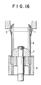
- Figs. 13 to 16 are views illustrating the steps of inserting the coil 1 into the slots 2, in which 5 is a coil guide holder, 6 are coil guides supported by the coil guide holder 5, and 7 is a coil pusher slidable for a reciprocating motion along the coil guides 6.
- the coil 1 which was prepared by winding an electric conductor into a ring having a necessary number of turns and formed to have a radial projections and grooves by a number corresponding to the pole number, is mounted to the coil guides 6 (see Fig. 13) .
- the coil 1 is lift up by the coil pusher 7 so that the coil 1 is brought into contact with the core 3 and deformed (see Fig. 14).
- the coil pusher 7 is lowered to the original position (see Fig. 16).
- the coil 1 is deformed while it is being hit and rubbed against the core 3, the coil guides 6, coil pusher 7 and the like under an insertion pressure, so that the insulation coating of the coil 1 and the core 3 may be damaged especially when the stator 4 having a high space factor coil is to be manufactured.
- the coil 1 is aligned to the core 3 before insertion, it is in a misaligned state when inserted and the slot coil portion and the coil end portion are not in alignment, so that the space factor of the coil with respect to the core, the space efficiency and the cooling efficiency are disadvantageously lowered.
- the stator manufacturing method of the present invention has been made to solve the above problem and has as its object the provision of a stator manufacturing method which can manufacture a stator which has high coil space factor with respect to the core, high space efficiency and high cooling efficiency.
- the stator manufacturing method of the present invention comprises the steps of pre-forming the coil into a chevron-shape before mounting on the core, the chevron-shaped coil comprising a front coil end portion positioned within the inner diameter of the core, slot coil portions positioned at the diameter of the slots and having substantially the same configuration as the slots, a rear coil end portion positioned between the slot coil portions, and a transition coil portions positioned between the front coil end portion and the slot coil portions, inserting the pre-formed coil from into the core from its end face, and deforming the front coil end portion toward the outside of the inner diameter of the core.
- the coil is formed into a configuration corresponding to the coil configuration inserted in the core, and the coil is inserted into the core.
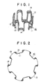
- Fig. 1 is an overall perspective view of one embodiment of the present invention
- Fig. 2 is a plan view of Fig. 1
- Fig. 3 is a view illustrating the manner in which the coil is pressure-formed
- Figs. 4 to 6 are views illustrating the rear coil end where the first phase coil, the second phase coil and the third phase coil are inserted into the respective core slots
- Fig. 7 is a view illustrating the state in which the coil of Fig. 1 is inserted from the core end face
- Fig. 8 is a sectional view illustrating the core of another embodiment of the present invention
- Fig. 9 is a sectional view illustrating the core of a still another embodiment of the present invention
- Fig. 10 is a perspective view of one example a conventional coil
- Fig. 11 is a perspective view of the core
- Fig. 12 is a perspective view of the stator in which the coil is wound on the core
- Figs. 13 to 16 are views illustrating the steps of inserting the coil into the core.
- Fig. 1 is a perspective view of one embodiment of a coil mounted to a vehicular ac generator core
- Fig. 2 is a plan view of Fig. 1, the same components as those in Figs. 10 to 16 are designated by the same reference numerals and their description is omitted.
- 10 is a coil to be inserted into the core 3, and the coil 10 is pre-formed from the star-shaped coil 1 into a configuration corresponding to that of the coil inserted in the core 3.
- 11 are front coil end portions which become front coil ends after the coil 10 is inserted in the core 3 and are positioned inside of the inner diameter of the core 3.
- 12 is slot coil portions which are disposed within the slots 2 when the coil 10 is mounted to the core 3.
- the slot coil portions 12 are positioned at the diameter of the slots 2 of the core 3 and configured in correspondence with the slots 2.
- 13 are rear coil end portions disposed between the slot coil end portions 12, and 14 are transition coil portions disposed between the front coil end portions 11 and the slot coil portions 12.
- Fig. 3 is a view illustrating the manner in which the coil 10 is pre-formed, wherein 20 is a pressure-forming jig having a configuration similar to that of the slots 2 of the core 3, and 21 is a pressure punch for pressing the coil contained within the grooves 22 formed in the pressure-forming jig 20 with a static pressure.
- the coil 10 is formed by the pressure-forming jig 20 and the pressure punch 21 in several steps so that the electrically insulating coating on the coil 10 is never damaged during this forming operation.
- Figs. 4 to 6 illustrate the state of the rear coil end portions 13 when the first, the second and the third phase coils 10, respectively, are inserted into the core 3.
- the rear coil end portions 13 of the respective phase have different configurations so that the insertion of each phase coil 10 is obstacled.
- the chevron-shaped coils 10 of as above-formed are inserted into the core 3 from its end face.
- the slot coil portion 12 is positioned at the same diameter as the slots 2 during the entire insertion process, and the front coil end portions 11 are inside of the inner diameter of the core 3, and in this situation, the coil end portions 11 are forced to override the teeth 8 to be inserted into the core 3.
- the transition coils 14 pass through the slot opening 9 of the core 3 in the state where they are stacked in a vertical position. Thereafter, the the front coil end portions 11 are deformed outwardly of the inner diameter of the core 3 and the winding operation of the coil 10 onto the core 3 is completed.
- the above deformations of the coil conductors are carried out with relatively small forces, so that no electrical insulation on the front coil end portions 11 is destroyed.
- Figs. 8 and 9 are sectional views illustrating the stator to which coil conductors 30 of a rectangular cross-section are inserted into the slot 2 by the same process as that described above.
- stator manufacturing method of the present invention since the coil is pre-formed into a configuration corresponding to that after it is inserted into the core and this pre-formed coil is inserted into the coil, the coil is not subjected to deformation even when it is inserted into the core and the electrical insulating coatings on the coil and the core are not damaged. Also, since the slot coil portions are inserted into the core slots with their alignment is maintained, the space factor of the coil in the slots is high and the alignment is maintained at the front and the rear coil end portions, so that the high space factor and the cooling efficiency are advantageously obtained.
Landscapes
- Engineering & Computer Science (AREA)
- Manufacturing & Machinery (AREA)
- Power Engineering (AREA)
- Manufacture Of Motors, Generators (AREA)
- Windings For Motors And Generators (AREA)
Applications Claiming Priority (2)
| Application Number | Priority Date | Filing Date | Title |
|---|---|---|---|
| JP2108640A JP2523933B2 (ja) | 1990-04-26 | 1990-04-26 | ステ―タの製造方法 |
| JP108640/90 | 1990-04-26 |
Publications (3)
| Publication Number | Publication Date |
|---|---|
| EP0455121A2 true EP0455121A2 (de) | 1991-11-06 |
| EP0455121A3 EP0455121A3 (en) | 1991-12-18 |
| EP0455121B1 EP0455121B1 (de) | 1996-07-03 |
Family
ID=14489920
Family Applications (1)
| Application Number | Title | Priority Date | Filing Date |
|---|---|---|---|
| EP91106574A Expired - Lifetime EP0455121B1 (de) | 1990-04-26 | 1991-04-24 | Verfahren zur Herstellung eines Stators |
Country Status (5)
| Country | Link |
|---|---|
| US (1) | US5113573A (de) |
| EP (1) | EP0455121B1 (de) |
| JP (1) | JP2523933B2 (de) |
| KR (1) | KR940002364B1 (de) |
| DE (1) | DE69120597T2 (de) |
Cited By (6)
| Publication number | Priority date | Publication date | Assignee | Title |
|---|---|---|---|---|
| WO1997024792A1 (de) * | 1995-12-30 | 1997-07-10 | Robert Bosch Gmbh | Stator für elektrische maschine |
| WO1998048500A3 (en) * | 1997-04-18 | 1999-02-11 | Kone Corp | Procedure for preparing the windings for an electric motor |
| WO2006024578A1 (de) * | 2004-08-27 | 2006-03-09 | Robert Bosch Gmbh | Drehstromgenerator |
| WO2008071147A3 (de) * | 2006-12-14 | 2008-09-12 | Luk Lamellen & Kupplungsbau | Elektrische maschine und verfahren zum herstellen einer solchen |
| EP2709247A1 (de) * | 2004-03-31 | 2014-03-19 | Kabushiki Kaisha Toyota Jidoshokki | Elektrische Drehmaschine |
| EP2226923B1 (de) * | 2009-03-03 | 2015-06-10 | GE Energy Power Conversion Technology Limited | Spulen |
Families Citing this family (31)
| Publication number | Priority date | Publication date | Assignee | Title |
|---|---|---|---|---|
| DE4300764C2 (de) * | 1993-01-14 | 1997-09-04 | Reinhard Napierski | Verfahren und Vorrichtung zur Herstellung einer Wellenwicklung |
| US5732900A (en) * | 1995-10-30 | 1998-03-31 | Electrowind, Inc. | Tool including a winding spindle for winding and forming dynamoelectric machine field windings |
| US5860615A (en) * | 1995-10-30 | 1999-01-19 | Labinal Components And Systems, Inc. | Tool including winding spindle for winding and forming dynamoelectric machine field windings |
| WO1998011653A1 (en) * | 1996-09-10 | 1998-03-19 | Labinal Components & Systems, Inc. | Method and apparatus for winding and forming field windings for dynamo-electric machines |
| DE69731319T2 (de) * | 1996-11-15 | 2006-02-23 | Globe Motors, Inc., Lombard | Werkzeug zum formen von ständerdrähten |
| US5895004A (en) * | 1997-04-07 | 1999-04-20 | Labinal Components & Systems, Inc. | Coil winding apparatus for large diameter magnetic rings |
| ES2203986T5 (es) * | 1997-10-16 | 2007-12-01 | Denso Corporation | Metodo y aparato para arrollar las partes de vuelta de segmentos conductores de estator en u. |
| US6616082B2 (en) | 2000-10-16 | 2003-09-09 | Globe Motors, Inc. | Machine for winding dynamo-electric stators |
| KR100373303B1 (ko) * | 2000-11-21 | 2003-02-25 | 네오다인코리아 주식회사 | 모터용 고정자 코일의 권선방법 |
| US6695244B2 (en) * | 2001-07-17 | 2004-02-24 | Globe Motors, Inc. | Winding tool for forming wire coils in a stator stack including radially movable forming members |
| JP3561249B2 (ja) * | 2001-09-17 | 2004-09-02 | 三菱電機株式会社 | 交流発電機の固定子およびその製造方法 |
| JP2005124362A (ja) * | 2003-10-20 | 2005-05-12 | Toyota Industries Corp | 巻き線用ケーブル及び電機子 |
| JP2005124361A (ja) * | 2003-10-20 | 2005-05-12 | Toyota Industries Corp | 回転電機およびその製造方法 |
| US7419116B2 (en) * | 2004-04-26 | 2008-09-02 | Globe Motors, Inc. | Method and apparatus for winding field coils for dynamo-electric machines |
| FR2888059B1 (fr) * | 2005-06-30 | 2007-09-07 | Valeo Equip Electr Moteur | Enroulement de phase pour un stator de machine electrique tournante et stator equipe d'un tel enroulement de phase |
| DE102005048094A1 (de) * | 2005-09-30 | 2007-04-05 | Robert Bosch Gmbh | Verfahren und Vorrichtung zur Herstellung einer Wicklung für elektrische Maschinen |
| TWD124587S1 (zh) * | 2007-05-25 | 2008-09-01 | 三菱電機股份有限公司 | 車輛用交流發電機之定子 |
| USD616818S1 (en) | 2008-05-28 | 2010-06-01 | Denso Corporation | Stator for a vehicle rotary electric machine |
| USD624497S1 (en) | 2008-05-29 | 2010-09-28 | Denso Corporation | Stator for a vehicle rotary electric machine |
| JP5234111B2 (ja) * | 2008-07-14 | 2013-07-10 | アイシン・エィ・ダブリュ株式会社 | ステータ及びその製造方法 |
| US8040007B2 (en) | 2008-07-28 | 2011-10-18 | Direct Drive Systems, Inc. | Rotor for electric machine having a sleeve with segmented layers |
| JP2010104145A (ja) | 2008-10-23 | 2010-05-06 | Aisin Aw Co Ltd | 回転電機 |
| JP5385166B2 (ja) * | 2010-01-22 | 2014-01-08 | 日立オートモティブシステムズ株式会社 | 回転電機 |
| JP5509896B2 (ja) * | 2010-02-10 | 2014-06-04 | 株式会社豊田自動織機 | ステータコイル及びモータ |
| TWI413344B (zh) * | 2010-05-05 | 2013-10-21 | Taigene Electric Machinery Co Ltd | 電動機定部鐵心繞線方法及結構 |
| TWI517524B (zh) | 2014-07-01 | 2016-01-11 | 勝利工業股份有限公司 | 交流發電機定子及定子繞組 |
| TWI517530B (zh) | 2014-07-01 | 2016-01-11 | Victory Ind Corp | Alternator stator windings and stator windings |
| WO2016143153A1 (ja) * | 2015-06-18 | 2016-09-15 | 株式会社林工業所 | 電気エネルギーと機械エネルギーとを変換する電気機械装置用のコイル、その製造方法、及びコイルのティースに対する組付方法 |
| JP6299722B2 (ja) * | 2015-10-22 | 2018-03-28 | トヨタ自動車株式会社 | コイルエンド折曲治具及びコイルエンド折曲方法 |
| FR3062254B1 (fr) * | 2017-01-23 | 2019-06-07 | Valeo Equipements Electriques Moteur | Stator bobine pour machine electrique tournante |
| RU2746441C1 (ru) * | 2020-06-02 | 2021-04-14 | Сотис АГ | Громковоритель |
Family Cites Families (9)
| Publication number | Priority date | Publication date | Assignee | Title |
|---|---|---|---|---|
| DE209091C (de) * | ||||
| DE730684C (de) * | 1940-10-22 | 1943-01-15 | Johann Schloegl | Verfahren und Vorrichtung zum Einfuehren der Wicklung in den Stator elektrischer Maschinen |
| FR2483702A1 (fr) * | 1980-05-30 | 1981-12-04 | Paris & Du Rhone | Procede et dispositif pour la realisation du bobinage d'un stator d'alternateur de petite puissance |
| JPS619142A (ja) * | 1984-06-20 | 1986-01-16 | Hitachi Ltd | 3相交流発電機固定子の巻線方法 |
| JPS6218952A (ja) * | 1985-07-15 | 1987-01-27 | Mitsubishi Electric Corp | 車両用交流発電機の電機子の製造方法 |
| IT1182652B (it) * | 1985-11-05 | 1987-10-05 | Pavesi & C Spa Off Mec | Dispositivo per inserire matasse preavvolte nelle cave di uno stato re di una macchina dinamoelettrica ed apparecchiatura utilizzante tale dispositivo |
| JPS62147932A (ja) * | 1985-12-19 | 1987-07-01 | Mitsubishi Electric Corp | ステ−タにおけるウエツジの插入方法 |
| JPH0832148B2 (ja) * | 1986-08-26 | 1996-03-27 | 日本電装株式会社 | コイル挿入装置 |
| FR2608334B1 (fr) * | 1986-12-16 | 1989-03-31 | Paris & Du Rhone | Procede de bobinage d'un stator de machine tournante electrique, et dispositif pour la mise en oeuvre de ce procede |
-
1990
- 1990-04-26 JP JP2108640A patent/JP2523933B2/ja not_active Expired - Lifetime
-
1991
- 1991-02-20 KR KR1019910002696A patent/KR940002364B1/ko not_active Expired - Fee Related
- 1991-04-24 US US07/690,248 patent/US5113573A/en not_active Expired - Lifetime
- 1991-04-24 DE DE69120597T patent/DE69120597T2/de not_active Expired - Fee Related
- 1991-04-24 EP EP91106574A patent/EP0455121B1/de not_active Expired - Lifetime
Cited By (11)
| Publication number | Priority date | Publication date | Assignee | Title |
|---|---|---|---|---|
| WO1997024792A1 (de) * | 1995-12-30 | 1997-07-10 | Robert Bosch Gmbh | Stator für elektrische maschine |
| CN1097334C (zh) * | 1995-12-30 | 2002-12-25 | 罗伯特-博希股份公司 | 电机的定子 |
| KR100433117B1 (ko) * | 1995-12-30 | 2004-09-13 | 로베르트 보쉬 게엠베하 | 전기기계용고정자 |
| WO1998048500A3 (en) * | 1997-04-18 | 1999-02-11 | Kone Corp | Procedure for preparing the windings for an electric motor |
| US6581270B1 (en) | 1997-04-18 | 2003-06-24 | Kone Corporation | Method for preparing the windings for an electric motor |
| EP2709247A1 (de) * | 2004-03-31 | 2014-03-19 | Kabushiki Kaisha Toyota Jidoshokki | Elektrische Drehmaschine |
| EP1583205B1 (de) * | 2004-03-31 | 2014-07-02 | Kabushiki Kaisha Toyota Jidoshokki | Verfahren zur Montage einer Spule auf dem Kern der elektrischen Drehmaschine |
| WO2006024578A1 (de) * | 2004-08-27 | 2006-03-09 | Robert Bosch Gmbh | Drehstromgenerator |
| CN101010850B (zh) * | 2004-08-27 | 2011-12-14 | 罗伯特·博世有限公司 | 交流发电机 |
| WO2008071147A3 (de) * | 2006-12-14 | 2008-09-12 | Luk Lamellen & Kupplungsbau | Elektrische maschine und verfahren zum herstellen einer solchen |
| EP2226923B1 (de) * | 2009-03-03 | 2015-06-10 | GE Energy Power Conversion Technology Limited | Spulen |
Also Published As
| Publication number | Publication date |
|---|---|
| JPH048149A (ja) | 1992-01-13 |
| US5113573A (en) | 1992-05-19 |
| KR910019307A (ko) | 1991-11-30 |
| DE69120597T2 (de) | 1996-11-28 |
| EP0455121B1 (de) | 1996-07-03 |
| KR940002364B1 (ko) | 1994-03-23 |
| DE69120597D1 (de) | 1996-08-08 |
| HK1001707A1 (en) | 1998-07-03 |
| JP2523933B2 (ja) | 1996-08-14 |
| EP0455121A3 (en) | 1991-12-18 |
Similar Documents
| Publication | Publication Date | Title |
|---|---|---|
| EP0455121A2 (de) | Verfahren zur Herstellung eines Stators | |
| US4215464A (en) | Method of making a stator connection assembly | |
| US4829206A (en) | Armature for an electric rotary machine and method of manufacturing the same | |
| US6389678B1 (en) | Method of constructing a salient pole motor | |
| US7600311B2 (en) | Method for producing a magnetically excitable core comprising a core winding for an electric machine | |
| EP0695019B1 (de) | Elektromachinerotor, insbesondere für einen Elektromotor, der eine Wärmkraftmaschine eines Fahrzeugs anfählt und Vorrichtung für seine Herstellung | |
| US6742238B2 (en) | Flare tooth stator for an AC generator | |
| US4543708A (en) | Method of manufacturing an armature | |
| JPS63194543A (ja) | 車両用交流発電機の固定子及びその製造方法 | |
| US4176444A (en) | Method and apparatus for assembling dynamoelectric machine stators | |
| US6020667A (en) | Stator bonding nib | |
| US4318022A (en) | End turn and terminal support for a stator assembly | |
| EP0612139B2 (de) | Gerät und Verfahren zur Herstellung von Statoren elektrischer Motoren und desgleichen sowie Klemmbrett dafür | |
| EP0114260B1 (de) | Verfahren und Vorrichtung zum Einsetzen von Spulen in Nuten von Statorkernen | |
| JPS63305737A (ja) | 回転電機子の製造方法 | |
| EP0570031A2 (de) | Ständerendglied und Montageverfahren auf dem Ständer | |
| US6851175B2 (en) | Wound stator core and method of making | |
| US20040187293A1 (en) | Radial insertion of stator hairpin windings | |
| US6282775B1 (en) | Methods for injecting stator winding coil groups into a stator core | |
| KR20190037759A (ko) | 분포권 평각형 전기자 권선 및 이를 포함하는 모터, 그리고 이들의 제조방법 | |
| EP0371933A1 (de) | Verfahren zur Herstellung einer Wicklung für den Ständer einer elektrischen Gleichstrommaschine | |
| US4998339A (en) | Process for fabrication of an iron member with a winding for generation of electromagnetic fields | |
| HK1001707B (en) | Stator manufacturing method | |
| JPH11289721A (ja) | 積層固定子鉄心とその製造方法 | |
| US6011340A (en) | Dynamo-electric apparatus and methods for manufacturing |
Legal Events
| Date | Code | Title | Description |
|---|---|---|---|
| PUAI | Public reference made under article 153(3) epc to a published international application that has entered the european phase |
Free format text: ORIGINAL CODE: 0009012 |
|
| PUAL | Search report despatched |
Free format text: ORIGINAL CODE: 0009013 |
|
| AK | Designated contracting states |
Kind code of ref document: A2 Designated state(s): DE FR GB IT |
|
| AK | Designated contracting states |
Kind code of ref document: A3 Designated state(s): DE FR GB IT |
|
| 17P | Request for examination filed |
Effective date: 19920128 |
|
| 17Q | First examination report despatched |
Effective date: 19931006 |
|
| GRAA | (expected) grant |
Free format text: ORIGINAL CODE: 0009210 |
|
| AK | Designated contracting states |
Kind code of ref document: B1 Designated state(s): DE FR GB IT |
|
| ITF | It: translation for a ep patent filed | ||
| REF | Corresponds to: |
Ref document number: 69120597 Country of ref document: DE Date of ref document: 19960808 |
|
| GRAH | Despatch of communication of intention to grant a patent |
Free format text: ORIGINAL CODE: EPIDOS IGRA |
|
| REG | Reference to a national code |
Ref country code: GB Ref legal event code: 727 |
|
| REG | Reference to a national code |
Ref country code: GB Ref legal event code: 727A |
|
| ET | Fr: translation filed | ||
| REG | Reference to a national code |
Ref country code: GB Ref legal event code: 727B |
|
| REG | Reference to a national code |
Ref country code: GB Ref legal event code: SP |
|
| PLBE | No opposition filed within time limit |
Free format text: ORIGINAL CODE: 0009261 |
|
| STAA | Information on the status of an ep patent application or granted ep patent |
Free format text: STATUS: NO OPPOSITION FILED WITHIN TIME LIMIT |
|
| 26N | No opposition filed | ||
| REG | Reference to a national code |
Ref country code: GB Ref legal event code: IF02 |
|
| PGFP | Annual fee paid to national office [announced via postgrant information from national office to epo] |
Ref country code: IT Payment date: 20090423 Year of fee payment: 19 Ref country code: DE Payment date: 20090420 Year of fee payment: 19 |
|
| PGFP | Annual fee paid to national office [announced via postgrant information from national office to epo] |
Ref country code: GB Payment date: 20090422 Year of fee payment: 19 |
|
| PGFP | Annual fee paid to national office [announced via postgrant information from national office to epo] |
Ref country code: FR Payment date: 20100521 Year of fee payment: 20 |
|
| GBPC | Gb: european patent ceased through non-payment of renewal fee |
Effective date: 20100424 |
|
| PG25 | Lapsed in a contracting state [announced via postgrant information from national office to epo] |
Ref country code: DE Free format text: LAPSE BECAUSE OF NON-PAYMENT OF DUE FEES Effective date: 20101103 |
|
| PG25 | Lapsed in a contracting state [announced via postgrant information from national office to epo] |
Ref country code: GB Free format text: LAPSE BECAUSE OF NON-PAYMENT OF DUE FEES Effective date: 20100424 Ref country code: IT Free format text: LAPSE BECAUSE OF NON-PAYMENT OF DUE FEES Effective date: 20100424 |