EP0455318A2 - Module d'illumination - Google Patents
Module d'illumination Download PDFInfo
- Publication number
- EP0455318A2 EP0455318A2 EP91250117A EP91250117A EP0455318A2 EP 0455318 A2 EP0455318 A2 EP 0455318A2 EP 91250117 A EP91250117 A EP 91250117A EP 91250117 A EP91250117 A EP 91250117A EP 0455318 A2 EP0455318 A2 EP 0455318A2
- Authority
- EP
- European Patent Office
- Prior art keywords
- lamp
- lamp holder
- unit according
- lighting unit
- power supply
- Prior art date
- Legal status (The legal status is an assumption and is not a legal conclusion. Google has not performed a legal analysis and makes no representation as to the accuracy of the status listed.)
- Granted
Links
Images


Classifications
-
- F—MECHANICAL ENGINEERING; LIGHTING; HEATING; WEAPONS; BLASTING
- F21—LIGHTING
- F21V—FUNCTIONAL FEATURES OR DETAILS OF LIGHTING DEVICES OR SYSTEMS THEREOF; STRUCTURAL COMBINATIONS OF LIGHTING DEVICES WITH OTHER ARTICLES, NOT OTHERWISE PROVIDED FOR
- F21V19/00—Fastening of light sources or lamp holders
- F21V19/0005—Fastening of light sources or lamp holders of sources having contact pins, wires or blades, e.g. pinch sealed lamp
-
- F—MECHANICAL ENGINEERING; LIGHTING; HEATING; WEAPONS; BLASTING
- F21—LIGHTING
- F21V—FUNCTIONAL FEATURES OR DETAILS OF LIGHTING DEVICES OR SYSTEMS THEREOF; STRUCTURAL COMBINATIONS OF LIGHTING DEVICES WITH OTHER ARTICLES, NOT OTHERWISE PROVIDED FOR
- F21V17/00—Fastening of component parts of lighting devices, e.g. shades, globes, refractors, reflectors, filters, screens, grids or protective cages
- F21V17/06—Fastening of component parts of lighting devices, e.g. shades, globes, refractors, reflectors, filters, screens, grids or protective cages the fastening being onto or by the lampholder
-
- F—MECHANICAL ENGINEERING; LIGHTING; HEATING; WEAPONS; BLASTING
- F21—LIGHTING
- F21V—FUNCTIONAL FEATURES OR DETAILS OF LIGHTING DEVICES OR SYSTEMS THEREOF; STRUCTURAL COMBINATIONS OF LIGHTING DEVICES WITH OTHER ARTICLES, NOT OTHERWISE PROVIDED FOR
- F21V7/00—Reflectors for light sources
-
- F—MECHANICAL ENGINEERING; LIGHTING; HEATING; WEAPONS; BLASTING
- F21—LIGHTING
- F21V—FUNCTIONAL FEATURES OR DETAILS OF LIGHTING DEVICES OR SYSTEMS THEREOF; STRUCTURAL COMBINATIONS OF LIGHTING DEVICES WITH OTHER ARTICLES, NOT OTHERWISE PROVIDED FOR
- F21V19/00—Fastening of light sources or lamp holders
- F21V19/0075—Fastening of light sources or lamp holders of tubular light sources, e.g. ring-shaped fluorescent light sources
- F21V19/008—Fastening of light sources or lamp holders of tubular light sources, e.g. ring-shaped fluorescent light sources of straight tubular light sources, e.g. straight fluorescent tubes, soffit lamps
- F21V19/009—Fastening of light sources or lamp holders of tubular light sources, e.g. ring-shaped fluorescent light sources of straight tubular light sources, e.g. straight fluorescent tubes, soffit lamps the support means engaging the vessel of the source
Definitions
- the invention relates to a lighting unit of the type specified in the preamble of claim 1.
- Such a lighting unit with at least two glass bulb lamps connected in series is known from EP-B1 0 169 165 known.
- the lamps are held on one side by a carrier element inserted into a transparent tube.
- the carrier element carries the current leads of the lamps, these being guided to connections at the ends of the tube and being mounted in the carrier element.
- the lamps have free wire connections which are clamped directly into a corresponding recess in the carrier element.
- the carrier element is also designed as a continuous flexible plastic profile and has on its side facing away from the lamps webs which separate several chambers from one another in which the one conductor of the power supply line is guided.
- the free wire connections of the lamps are led through the plastic profile to the chambers, where they are either connected to each other for series connection or to a conductor leading to one of the two power connections. Furthermore, the webs or edges of the plastic profile are supported on the inside of the transparent tube.
- the known lighting unit has the disadvantage that the individual elements, in particular the carrier element, expand due to the heat generated by the lamps. This leads to strong tension within the tube, which results in premature material fatigue in both the tube and the support element. The material fatigue manifests itself in the form of material cracks, which are associated with a reduced strength or load-bearing capacity of the tube or the support element. Due to the expansion of the lighting unit, the mounting device of the lighting unit can also be damaged. Furthermore points the known version has a low luminosity in relation to the number of lamps and the complex design, so that the area of use of the known lighting unit is restricted.
- the invention has for its object to provide a lighting unit of the type mentioned while eliminating the disadvantages mentioned, a construction with which the light output of the lamps of the lighting unit is optimized with little design effort.
- the carrier element should also be made even more functional overall.
- the invention is based on the finding that by including an optically shaped reflector in the lamp holder, the light yield which can be achieved with such a lighting unit can be substantially increased by simple means. Furthermore, the heat conduction in the lamp holder can also be reduced, since the reflector has a heat-insulating effect with respect to the lamp holder. This advantageously reduces the thermal expansions of the lamp holder.
- the reflector can therefore also be arranged relatively closely adjacent to the filament of the respective lamp, so that the reflector surface need only be dimensioned relatively small in order to additionally throw back a substantial proportion of the otherwise undirected light.
- each incandescent lamp has a concave shape, a focal point or a correspondingly two-dimensionally deformed reflector with a focal axis, and the filament of the incandescent lamp held in the lamp holder is arranged essentially at the focal point of the reflector. This advantageously optimizes the luminous efficacy of the lamps, which also extends the area of application of the lighting unit.
- a lamp is attached to a lamp holder.
- the individual lamp holders are arranged at a distance from one another and are only connected to one another via the power leads that are displaceably mounted in the lamp holders.
- the remaining thermal expansions of the lamp holders which result from the heating associated with the start-up of the lamps, are compensated for by the distances between the lamp holders. This avoids the tension that may otherwise occur and the associated disturbing cracking noises, and the expansion does not stress the transparent tube and the lamp holder.
- the light bulbs are positioned in the lamp holder such that the base of the lamp is clamped in the lamp holder. Even with mechanical Loads, the lamps are thus firmly attached to the lamp holder.
- the lamp support has a cross section such that it is supported on the transparent tube with the side edges of the reflector or via insulating webs. This rattles the lamp holder in the transparent tube in a simple manner when moving the tube.
- the radius of the reflector is also larger than the inner radius of the transparent glass tube and the length of the reflector is preferably less than half the length of the lamp holder.
- the reflector consists of a highly reflective plastic, preferably "Pocan".
- the reflection of the light rays from the reflector is improved solely by this suitably selected material, without further measures being necessary. Due to the low density, the weight of the light unit hardly increases.
- the plastic forming the lamp holder is slightly elastic and has cutouts in which the lines forming the power supply can be clamped. Due to the elastic design, the lamp holder and the power supply lines can be easily installed and aligned and fixed within the tube. The cutouts receiving the power supply lines are separated by insulating webs, so that a short circuit between these power supply lines is excluded.
- the Power supply lines fix the individual lamp holders on the one hand and, on the other hand, allow the aforementioned thermal expansions to be compensated for by corresponding deformation in the areas between the lamp holders, so that the lamp holders do not move even when heated and therefore do not produce any disturbing cracking noises when the lamp is started up.
- slots are provided on an end face of the lamp holder, in which slots the line connections of the lamp are guided.
- the slots end in the recesses in the lamp holder for the power supply lines.
- a holder designed as a resilient clamp - and in particular made of one piece of plastic - is also provided on the lamp support for fastening the lamp in the region of the base.
- the bracket grips the base of the lamp by more than 180 °. As a result, the lamp is easily and securely held on the lamp holder.
- the inside of the tube has at least one, in particular in the longitudinal direction has a continuous, molded-on nose, which engages between two sub-regions of the lamp support, which are supported on the inside of the tube, in order to prevent mutual rotation.
- the nose is preferably designed to be continuous in the longitudinal direction.
- the lamp holder is also completely recessed in the area of the nose. The lamp holder is thus secured against rotation in a simple manner.
- the lighting unit according to the invention can be implemented in different glass tube lengths with different electrical outputs.
- several assemblies connected in series until the nominal voltage is reached and each containing a number of lamps are connected in parallel.
- the length and performance depend on the number of modules arranged in series but connected in parallel.
- the nominal voltage-carrying conductors are continuously guided in two of the three assemblies, while in the third chamber the two successive wire bridges connecting the series-connected lamps are accommodated, the two connection ends of the lamps connected to successive wire bridges by one receiving the wire bridges Recess blocking web are separated so that contacting successive bridges short-circuiting the lamp is prevented.
- the lighting unit according to the invention is preferably suitable for the production of relatively delicate lights, such as picture lights, piano lights, music stand lights, showcase lighting, Shelf lights, cabinet lights, niche lights and smaller light strips.
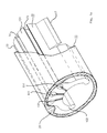
- FIGS. 1a and 1b a perspective view of a section of a lamp holder 10 and a hollow cylindrical and transparent glass tube 11 surrounding the lamp holder 10 are shown as part of the lighting unit according to the invention, viewed from two mutually distant sides.
- a variant of the lamp holder 10 is seen from one end face in FIG. 1a, and a further variant is seen from the other end face in FIG. 1b.
- the lamp support 10 extends coaxially to the axis of the glass tube 11 and is adapted to the inner cross section of the glass tube 11.
- the area 12 of the lamp support 10 which bears against the glass tube 11 has three recesses 13 to 15 which extend in the axial direction and are open towards the glass tube 11 and into which a current lead 16 (not shown in this figure) can be clamped.
- the lamp holder 10 is connected to a reflector 17 which is flush on its end face and is of concave design.
- the radius of the reflector 17 is larger than the radius of the glass tube 11, so that the light rays of a lamp 18 to be attached to the lamp carrier 10, not shown here, are reflected in the manner of a reflector that bundles the light rays.
- the lamp holder 10 is adapted to the lamp 18 to be arranged in profile and has the base 181 of the lamp 18 in the manner of a clamp, almost enclosing side areas 102, which enable the lamp 18 to be clamped to the lamp holder 10.
- the reflector 17 extends laterally beyond the lamp holder 10 to the inner surface of the glass tube 11, where the side edges of the reflector 17 each abut. In cooperation with the area 12 resting on the glass tube 11 and the reflector 17 supported laterally on the glass tube 11, the lamp holder 10 is fixed in the radial direction in the glass tube 11. Uncontrollable movements of the glass tube 11 due to inertial forces are therefore excluded.
- the lamp holder 10 made of plastic is elastic. This simplifies in particular the assembly of the power supply lines 16 and the lamp 18. Furthermore, the reflector 17 is smaller in the axial direction than half the length of the lamp holder 10.
- the reflector 17 consists of the reflective polybintylene terephalate plastic with the trade name "Pocan", which ensures a high reflection factor of the light emitted by the associated lamp.
- 10 recesses 13 to 15 are provided at the end of the lamp holder located away from the reflector 17 as radially directed slots 131, 141 and 151 which penetrate the lamp holder 10 and which connect the connecting wires 19 of the lamp 18 serve as bushings.
- a connection possibility of the lamps 18 of this variant of the lamp holder 10 is explained in more detail below with reference to FIGS. 3a and 3b.
- the cutout 14 is divided in half in the center with respect to the lamp holder 10 by an insulating web 140, the insulating web 140 separating and isolating the current leads 16 running in the cutout 14 from one another.
- Adjacent to the insulating web 140 are two bores 142 and 143 which pass through the lamp holder and are adapted to the connecting lines 19.
- the lamps 18 are here with the bridges of the power supply line 16 provided in the middle recess grouped in series.
- a lamp group consists of 50 many lamps connected in series so that the nominal voltage is reached at the connection ends of the light unit. To increase the output of a lighting unit, several lamp groups are connected in series, which increases the length of the lighting unit.
- the power supply lines 16 of the recesses 13 are then connected to leads leading to one of the connecting ends (in the outer recesses), so that these are fed over the length of the entire lighting unit to the ends of the lighting unit Poles of the nominal voltage are connected.
- the lamp holder 10 also consists of an insulating, elastic plastic, the area between the cutouts 13 to 15 serving as an insulating web 101 with respect to the power supply lines 16 to be clamped in, so that a short circuit is avoided from the outset.
- the glass tube 11 has on its inside the lamp holder 10 in the tangential direction fixing lugs 20.
- the lamp support 10 is designed in the region of the lugs 20 to match this.
- a nose 20 is arranged adjacent to the side of the recess 15.
- FIG. 2 shows a perspective view of the lamp holder 10 with the power supply lines 16 and the lamp 18.
- the lamp holder 10 corresponds to the lamp holder 10 already illustrated with reference to FIG. 1, the segment-like design of the lamp holder 10 partially enclosing the lamp 18 in its base region 181 being clearly recognizable with the aid of this figure.
- the essentially hollow-cylindrical lamp 18 extends from one end face of the lamp holder 10 to the other, the lamp 18 in the end region of the lamp 18 in the reflector 17 having increasingly smaller diameters in the direction of its free end.
- the incandescent filament 21 present in the bulb 18 is oriented within the lamp holder 10 such that the incandescent filament 21 of the bulb 18 is essentially at the focal point of the reflector 17. This ensures an optimal light yield of the light rays emanating from the incandescent filament 21.
- the lamp 18 is known under the name "Miniwatt” or “Pisello” incandescent lamp and can be interconnected with several other lamps 18 to form different voltage and / or power groups.
- the incandescent filament 21 is connected to two power supply lines 16 via connecting wires 22 and the connecting lines 19, the connecting lines 19 being guided in regions in the slots 131 and 151.
- a third power supply line runs in the recess 14 of the lamp body 10, the connection of the lamps 18 and the power supply lines 16 being illustrated and described with reference to FIG. 3.
- the power supply lines 16 do not have an insulating sleeve and connect individual lamp supports 10 in the glass tube 11 to one another.
- the outer recesses of the lamp holder are used by each lamp and its connecting wires, while a continuous line in the middle chamber leads to the connecting ends.
- two lamp groups can be used in one light unit - a fourth channel would be necessary for further lamp groups in order to be able to lead both poles of the supply voltage to all lamp groups.
- the lamp holder 10 With the assembly of the rigid power supply lines 16, the lamp holder 10 is positioned in the glass tube 11 in the axial direction.
- the rigid power supply lines 16 are pressed into the cutouts 13 to 15, the area forming an insulating web between the cutouts 13 to 15 separating the power supply lines 16 from one another in an insulating manner.
- the lamp 18 is clamped between the side areas 102 of the lamp holder 10 when the lighting unit according to the invention is installed and the connecting wires 22 are connected to the power supply lines 16 by the connecting lines 19.
- the lamp carriers 10, which are fully assembled with the lamps 18, are pushed into the glass tube 11 and closed by means of known end closures.
- the light unit can be manufactured in different lengths, from 200 to 1475 mm, whereby its light output varies according to the length.
- the exemplary embodiment permits directional, effective illumination of the object and, by using standardized long-life lamps, the lighting unit also has low power consumption.
- FIG. 3a ten variants of the lamp holder 10 of a lighting unit already described with reference to FIG. 1a are shown in a perspective view, and a switching arrangement of the power supply lines 16 with the respective lamps 18 of the lamp holder 10 are shown in a schematic representation (FIG. 3b).
- the lamps 18 are schematically stylized as arcs in the circuit arrangement. There are five lamps 18 each connected to a circuit, the lamps 18 each bridging the current leads of the recesses 13 and 15. A line 25 or 26 connecting the circuit of five lamps 18 with a connection 23 or 24 is provided in the middle recess 15. Adjacent to the connection are branch points 27 and 28, respectively, at which lines 25 and 26 of the two current crises are brought together. Analogously, the lighting unit can also be easily extended by a lamp series adapted to the respective nominal voltage. The same applies to this to provide a further line looping through the second outer connection in an additional groove.
- the embodiment of the invention is not limited to the preferred exemplary embodiment specified above. Rather, a number of variants are conceivable which make use of the solution shown even in the case of fundamentally different types.
Landscapes
- Engineering & Computer Science (AREA)
- General Engineering & Computer Science (AREA)
- Fastening Of Light Sources Or Lamp Holders (AREA)
- Arrangement Of Elements, Cooling, Sealing, Or The Like Of Lighting Devices (AREA)
- Non-Portable Lighting Devices Or Systems Thereof (AREA)
- Vehicle Body Suspensions (AREA)
- Fluid-Damping Devices (AREA)
- Absorbent Articles And Supports Therefor (AREA)
Applications Claiming Priority (2)
| Application Number | Priority Date | Filing Date | Title |
|---|---|---|---|
| DE4014277 | 1990-04-30 | ||
| DE4014277A DE4014277A1 (de) | 1990-04-30 | 1990-04-30 | Leuchteinheit |
Publications (3)
| Publication Number | Publication Date |
|---|---|
| EP0455318A2 true EP0455318A2 (fr) | 1991-11-06 |
| EP0455318A3 EP0455318A3 (en) | 1992-04-15 |
| EP0455318B1 EP0455318B1 (fr) | 1995-01-18 |
Family
ID=6405677
Family Applications (1)
| Application Number | Title | Priority Date | Filing Date |
|---|---|---|---|
| EP91250117A Expired - Lifetime EP0455318B1 (fr) | 1990-04-30 | 1991-04-26 | Module d'illumination |
Country Status (4)
| Country | Link |
|---|---|
| EP (1) | EP0455318B1 (fr) |
| JP (1) | JPH05120905A (fr) |
| AT (1) | ATE117418T1 (fr) |
| DE (2) | DE4014277A1 (fr) |
Families Citing this family (4)
| Publication number | Priority date | Publication date | Assignee | Title |
|---|---|---|---|---|
| DE9304477U1 (de) * | 1993-03-22 | 1993-06-24 | Fa. August Gärtner, 1000 Berlin | Leuchtelement |
| DE9304480U1 (de) * | 1993-03-22 | 1993-06-24 | Fa. August Gärtner, 1000 Berlin | Leuchteinheit |
| DE10102670B4 (de) * | 2001-01-17 | 2007-03-22 | Gärtner, Klaus | Leuchteinheit mit einer Anzahl von Glühlämpchen |
| CN1294448C (zh) * | 2003-10-16 | 2007-01-10 | 友达光电股份有限公司 | 背光模组的光源组件 |
Family Cites Families (4)
| Publication number | Priority date | Publication date | Assignee | Title |
|---|---|---|---|---|
| BE646252A (fr) * | 1962-08-23 | 1964-10-08 | ||
| DE3483115D1 (de) * | 1983-04-20 | 1990-10-11 | Youri Agabekov | Elektrische einspeisungsschiene. |
| DE3440185A1 (de) * | 1984-07-20 | 1986-01-30 | August Gärtner Inh. Klaus Gärtner, 1000 Berlin | Leuchteinheit |
| US4628421A (en) * | 1986-01-23 | 1986-12-09 | Saar Lawrence E | Strip lighting |
-
1990
- 1990-04-30 DE DE4014277A patent/DE4014277A1/de not_active Withdrawn
-
1991
- 1991-04-26 DE DE59104285T patent/DE59104285D1/de not_active Expired - Fee Related
- 1991-04-26 AT AT91250117T patent/ATE117418T1/de not_active IP Right Cessation
- 1991-04-26 EP EP91250117A patent/EP0455318B1/fr not_active Expired - Lifetime
- 1991-04-30 JP JP3098692A patent/JPH05120905A/ja active Pending
Also Published As
| Publication number | Publication date |
|---|---|
| EP0455318B1 (fr) | 1995-01-18 |
| EP0455318A3 (en) | 1992-04-15 |
| DE59104285D1 (de) | 1995-03-02 |
| JPH05120905A (ja) | 1993-05-18 |
| ATE117418T1 (de) | 1995-02-15 |
| DE4014277A1 (de) | 1991-10-31 |
Similar Documents
| Publication | Publication Date | Title |
|---|---|---|
| EP0303561B1 (fr) | Lampe | |
| DE1772182A1 (de) | Beleuchtungskoerper | |
| EP0138746B1 (fr) | Armature avec source lumineuse linéaire accessoire | |
| EP0486714A1 (fr) | Rail pour appareils d'éclairage | |
| EP0455318B1 (fr) | Module d'illumination | |
| DE69716701T2 (de) | Luminar | |
| EP3171077A1 (fr) | Technique d'éclairage anti-éblouissement | |
| EP3165821B1 (fr) | Élément de bande lumineuse allongé | |
| EP0169165B1 (fr) | Module d'illumination | |
| EP3477190A1 (fr) | Système optique pour un luminaire à del | |
| DE4026945A1 (de) | Heckleuchte fuer ein kraftfahrzeug | |
| EP0060900A1 (fr) | Bloc optique compartimenté pour véhicule | |
| DE19624789C2 (de) | Dachzeichen für Kraftfahrzeuge, insbesondere Taxidachzeichen | |
| DE102016107147B4 (de) | Schaltschrankleuchte mit verstellbarer Leuchtmittelplatine | |
| WO2022043032A1 (fr) | Agencement de microlentilles et dispositif micro-optique | |
| DE9304480U1 (de) | Leuchteinheit | |
| EP0392198B1 (fr) | Armature d'éclairage de forme allongée | |
| EP4048937B1 (fr) | Moyen d'éclairage linéaire à douille ayant une pluralité de diodes électroluminescentes | |
| EP0491249B1 (fr) | Porte-socle, installé dans une armature d'éclairage d'au moins une lampe fluorescente (tubulaire) avec des douilles à double fiche | |
| DE10102670B4 (de) | Leuchteinheit mit einer Anzahl von Glühlämpchen | |
| DE4410811A1 (de) | Leuchtelement | |
| EP1251723B1 (fr) | Ballast pour sources lumineuses de candélabres | |
| DE1958063U (de) | Signalgeberleuchte. | |
| DE20218277U1 (de) | Leuchte | |
| CH661111A5 (en) | Device for the simple fitting of electric lamps |
Legal Events
| Date | Code | Title | Description |
|---|---|---|---|
| PUAI | Public reference made under article 153(3) epc to a published international application that has entered the european phase |
Free format text: ORIGINAL CODE: 0009012 |
|
| AK | Designated contracting states |
Kind code of ref document: A2 Designated state(s): AT BE CH DE DK ES FR GB GR IT LI LU NL SE |
|
| PUAL | Search report despatched |
Free format text: ORIGINAL CODE: 0009013 |
|
| AK | Designated contracting states |
Kind code of ref document: A3 Designated state(s): AT BE CH DE DK ES FR GB GR IT LI LU NL SE |
|
| 17P | Request for examination filed |
Effective date: 19920729 |
|
| 17Q | First examination report despatched |
Effective date: 19931208 |
|
| GRAA | (expected) grant |
Free format text: ORIGINAL CODE: 0009210 |
|
| AK | Designated contracting states |
Kind code of ref document: B1 Designated state(s): AT BE CH DE DK ES FR GB GR IT LI LU NL SE |
|
| PG25 | Lapsed in a contracting state [announced via postgrant information from national office to epo] |
Ref country code: IT Free format text: LAPSE BECAUSE OF FAILURE TO SUBMIT A TRANSLATION OF THE DESCRIPTION OR TO PAY THE FEE WITHIN THE PRESCRIBED TIME-LIMIT;WARNING: LAPSES OF ITALIAN PATENTS WITH EFFECTIVE DATE BEFORE 2007 MAY HAVE OCCURRED AT ANY TIME BEFORE 2007. THE CORRECT EFFECTIVE DATE MAY BE DIFFERENT FROM THE ONE RECORDED. Effective date: 19950118 Ref country code: DK Effective date: 19950118 Ref country code: NL Effective date: 19950118 Ref country code: BE Effective date: 19950118 Ref country code: ES Free format text: THE PATENT HAS BEEN ANNULLED BY A DECISION OF A NATIONAL AUTHORITY Effective date: 19950118 Ref country code: GR Free format text: LAPSE BECAUSE OF FAILURE TO SUBMIT A TRANSLATION OF THE DESCRIPTION OR TO PAY THE FEE WITHIN THE PRESCRIBED TIME-LIMIT Effective date: 19950118 |
|
| REF | Corresponds to: |
Ref document number: 117418 Country of ref document: AT Date of ref document: 19950215 Kind code of ref document: T |
|
| REF | Corresponds to: |
Ref document number: 59104285 Country of ref document: DE Date of ref document: 19950302 |
|
| GBT | Gb: translation of ep patent filed (gb section 77(6)(a)/1977) |
Effective date: 19950202 |
|
| PGFP | Annual fee paid to national office [announced via postgrant information from national office to epo] |
Ref country code: CH Payment date: 19950411 Year of fee payment: 5 |
|
| PG25 | Lapsed in a contracting state [announced via postgrant information from national office to epo] |
Ref country code: SE Effective date: 19950418 |
|
| PG25 | Lapsed in a contracting state [announced via postgrant information from national office to epo] |
Ref country code: AT Effective date: 19950426 |
|
| PG25 | Lapsed in a contracting state [announced via postgrant information from national office to epo] |
Ref country code: LU Free format text: LAPSE BECAUSE OF NON-PAYMENT OF DUE FEES Effective date: 19950430 |
|
| ET | Fr: translation filed | ||
| NLV1 | Nl: lapsed or annulled due to failure to fulfill the requirements of art. 29p and 29m of the patents act | ||
| PLBE | No opposition filed within time limit |
Free format text: ORIGINAL CODE: 0009261 |
|
| STAA | Information on the status of an ep patent application or granted ep patent |
Free format text: STATUS: NO OPPOSITION FILED WITHIN TIME LIMIT |
|
| 26N | No opposition filed | ||
| PG25 | Lapsed in a contracting state [announced via postgrant information from national office to epo] |
Ref country code: CH Effective date: 19960430 Ref country code: LI Effective date: 19960430 |
|
| REG | Reference to a national code |
Ref country code: CH Ref legal event code: PL |
|
| REG | Reference to a national code |
Ref country code: GB Ref legal event code: IF02 |
|
| PGFP | Annual fee paid to national office [announced via postgrant information from national office to epo] |
Ref country code: GB Payment date: 20020405 Year of fee payment: 12 |
|
| PGFP | Annual fee paid to national office [announced via postgrant information from national office to epo] |
Ref country code: FR Payment date: 20020416 Year of fee payment: 12 |
|
| PG25 | Lapsed in a contracting state [announced via postgrant information from national office to epo] |
Ref country code: GB Free format text: LAPSE BECAUSE OF NON-PAYMENT OF DUE FEES Effective date: 20030426 |
|
| GBPC | Gb: european patent ceased through non-payment of renewal fee | ||
| PG25 | Lapsed in a contracting state [announced via postgrant information from national office to epo] |
Ref country code: FR Free format text: LAPSE BECAUSE OF NON-PAYMENT OF DUE FEES Effective date: 20031231 |
|
| REG | Reference to a national code |
Ref country code: FR Ref legal event code: ST |
|
| PGFP | Annual fee paid to national office [announced via postgrant information from national office to epo] |
Ref country code: DE Payment date: 20090502 Year of fee payment: 19 |
|
| PG25 | Lapsed in a contracting state [announced via postgrant information from national office to epo] |
Ref country code: DE Free format text: LAPSE BECAUSE OF NON-PAYMENT OF DUE FEES Effective date: 20101103 |