EP0455363A2 - Dämpfungsvorrichtung für Walzlager - Google Patents
Dämpfungsvorrichtung für Walzlager Download PDFInfo
- Publication number
- EP0455363A2 EP0455363A2 EP91303208A EP91303208A EP0455363A2 EP 0455363 A2 EP0455363 A2 EP 0455363A2 EP 91303208 A EP91303208 A EP 91303208A EP 91303208 A EP91303208 A EP 91303208A EP 0455363 A2 EP0455363 A2 EP 0455363A2
- Authority
- EP
- European Patent Office
- Prior art keywords
- bearing
- isolator assembly
- outer diameter
- radial
- retaining member
- Prior art date
- Legal status (The legal status is an assumption and is not a legal conclusion. Google has not performed a legal analysis and makes no representation as to the accuracy of the status listed.)
- Granted
Links
Images

Classifications
-
- F—MECHANICAL ENGINEERING; LIGHTING; HEATING; WEAPONS; BLASTING
- F16—ENGINEERING ELEMENTS AND UNITS; GENERAL MEASURES FOR PRODUCING AND MAINTAINING EFFECTIVE FUNCTIONING OF MACHINES OR INSTALLATIONS; THERMAL INSULATION IN GENERAL
- F16C—SHAFTS; FLEXIBLE SHAFTS; ELEMENTS OR CRANKSHAFT MECHANISMS; ROTARY BODIES OTHER THAN GEARING ELEMENTS; BEARINGS
- F16C35/00—Rigid support of bearing units; Housings, e.g. caps, covers
- F16C35/04—Rigid support of bearing units; Housings, e.g. caps, covers in the case of ball or roller bearings
- F16C35/06—Mounting or dismounting of ball or roller bearings; Fixing them onto shaft or in housing
- F16C35/07—Fixing them on the shaft or housing with interposition of an element
- F16C35/077—Fixing them on the shaft or housing with interposition of an element between housing and outer race ring
-
- F—MECHANICAL ENGINEERING; LIGHTING; HEATING; WEAPONS; BLASTING
- F16—ENGINEERING ELEMENTS AND UNITS; GENERAL MEASURES FOR PRODUCING AND MAINTAINING EFFECTIVE FUNCTIONING OF MACHINES OR INSTALLATIONS; THERMAL INSULATION IN GENERAL
- F16C—SHAFTS; FLEXIBLE SHAFTS; ELEMENTS OR CRANKSHAFT MECHANISMS; ROTARY BODIES OTHER THAN GEARING ELEMENTS; BEARINGS
- F16C33/00—Parts of bearings; Special methods for making bearings or parts thereof
- F16C33/30—Parts of ball or roller bearings
-
- F—MECHANICAL ENGINEERING; LIGHTING; HEATING; WEAPONS; BLASTING
- F16—ENGINEERING ELEMENTS AND UNITS; GENERAL MEASURES FOR PRODUCING AND MAINTAINING EFFECTIVE FUNCTIONING OF MACHINES OR INSTALLATIONS; THERMAL INSULATION IN GENERAL
- F16C—SHAFTS; FLEXIBLE SHAFTS; ELEMENTS OR CRANKSHAFT MECHANISMS; ROTARY BODIES OTHER THAN GEARING ELEMENTS; BEARINGS
- F16C27/00—Elastic or yielding bearings or bearing supports, for exclusively rotary movement
- F16C27/04—Ball or roller bearings, e.g. with resilient rolling bodies
-
- F—MECHANICAL ENGINEERING; LIGHTING; HEATING; WEAPONS; BLASTING
- F16—ENGINEERING ELEMENTS AND UNITS; GENERAL MEASURES FOR PRODUCING AND MAINTAINING EFFECTIVE FUNCTIONING OF MACHINES OR INSTALLATIONS; THERMAL INSULATION IN GENERAL
- F16C—SHAFTS; FLEXIBLE SHAFTS; ELEMENTS OR CRANKSHAFT MECHANISMS; ROTARY BODIES OTHER THAN GEARING ELEMENTS; BEARINGS
- F16C19/00—Bearings with rolling contact, for exclusively rotary movement
- F16C19/22—Bearings with rolling contact, for exclusively rotary movement with bearing rollers essentially of the same size in one or more circular rows, e.g. needle bearings
- F16C19/24—Bearings with rolling contact, for exclusively rotary movement with bearing rollers essentially of the same size in one or more circular rows, e.g. needle bearings for radial load mainly
- F16C19/26—Bearings with rolling contact, for exclusively rotary movement with bearing rollers essentially of the same size in one or more circular rows, e.g. needle bearings for radial load mainly with a single row of rollers
-
- F—MECHANICAL ENGINEERING; LIGHTING; HEATING; WEAPONS; BLASTING
- F16—ENGINEERING ELEMENTS AND UNITS; GENERAL MEASURES FOR PRODUCING AND MAINTAINING EFFECTIVE FUNCTIONING OF MACHINES OR INSTALLATIONS; THERMAL INSULATION IN GENERAL
- F16C—SHAFTS; FLEXIBLE SHAFTS; ELEMENTS OR CRANKSHAFT MECHANISMS; ROTARY BODIES OTHER THAN GEARING ELEMENTS; BEARINGS
- F16C2361/00—Apparatus or articles in engineering in general
- F16C2361/61—Toothed gear systems, e.g. support of pinion shafts
Definitions
- This invention relates to bearing isolators for mounting roller and/or ball bearings to supporting structures to isolate the supporting structures from the primarily radial vibrations and oscillations that the bearings, and the shafts rotatably supported thereby, are subject to. More particularly, this invention relates to isolators utilized in connection with roller and/or ball bearings rotatably supporting torque transmitting shafts in vehicular mechanical change gear transmissions.
- Resilient, flexible and/or cushioned bearing mounts or isolators utilized to isolate a support member from the vibrations and oscillations to which a bearing and the rotatably supported member, most often a shaft of some type, is subject to are, of course, well known in the prior art. Examples of such prior art devices may be seen by reference to United States patents Nos. 2,733,108; 3,309,154; 3,385,543; 3,709,570; 4,422,780 and 4,825,718, the disclosures of all of which are hereby incorporated by reference.
- Vehicular drivetrain components such as drive axles and mechanical change gear transmissions which utilize bearings, included ball and roller bearings, to rotatably support torque transmitting members, usually comprising some type of shafts, in a housing are well known in the prior art as may be seen by reference to United States Patents Nos. 4,788,889; 4,754,665; 4,736,643; 4,735,109; 4,709,590; 4,373,403; 4,761,867 and 4,678,017, the disclosures of all of which are hereby incorporated by reference.
- bearing isolators and/or of cushioned, resilient and/or flexible bearing mounts in drivetrain components to isolate the drive train component housing from shaft and gear vibrations and oscillations to reduce wear, to dampen the vibrations or oscillations, to increase vehicular occupant comfort and/or to minimize drive train noise is known.
- the previous resilient bearing mounts/bearing isolators were not totally satisfactory as the prior art devices were complicated and/or expensive to manufacture and/or assemble and/or utilized rubber and/or other nonmetallic materials which were expensive, not totally elastic, of an improper spring rate, not long wearing, and/or excessively sensitive to temperature and lubricants and/or did not limit deflection and stress of the resilient members.
- a bearing isolator comprising two principal components, each all metallic (preferably of a suitable steel) and each of a relatively simple and inexpensively produced structure.
- the principal components of the isolator of the present invention include (i) an annular, flanged wear ring/retainer sleeve for receipt in the bearing support apertures of the housing support walls, (ii) a generally tubular shaped radial wave spring which is resiliently radially deformable and is resiliently radially deformed between the inner diameter of the retainer and the outer diameter of the retained bearing outer race and (iii) a bump stop which limits travel and stress of the radial wave spring.
- the radial wave springs are made of a spring steel, such as for example SAE 6150 or the like, while the retainer and wear rings are made of a standard gear or shaft steel, such as SAE 1010, 1018 or 1020 or the like and are preferably surface hardened.
- Figure 1 is a partial sectional view of a vehicular transmission utilizing the bearing isolators of the present invention.
- Figure 1A is a schematic illustration of a typical change gear transmission as illustrated in Figure 1.
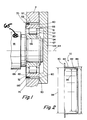
- Figure 2 is a sectional view of the retainer portion of the bearing isolator of the present invention.
- Figure 3 is an elevational view of a radial wave spring member of the bearing isolator of the present invention.
- Figure 4 is a side view, in section, of the radial wave spring illustrated in Figure 3.
- forward and rearward will refer to directions forward and rearward of the transmission as normally mounted in a vehicle.
- rightward and leftward will refer to directions in the drawings in connection with which the terminology is used.
- inwardly and outwardly will refer to directions toward and away from, respectively, the geometric center of the apparatus being described.
- upward and downward will refer to directions taken in the drawings in connection with which the terminology is used. All of the foregoing terms include the normal derivatives and equivalents thereof.
- Transmission 10 is a simple transmission, or transmission section, of the twin countershaft type which is well known in the prior art and which may be understood in greater detail by reference to U.S. patent Nos. 3,105,395; 3,611,823; 4,152,949; 4,445,393 and 4,194,410, the disclosures of all of which are hereby incorporated by reference.
- the illustrated transmission 10 comprises an input shaft 14 carrying an input gear 16 for rotation therewith.
- the input shaft 14 is intended to be driven by a prime mover (not shown) through a master clutch or torque converter (not shown) as is well known in the art.
- a pair of substantially identical countershafts 18 and 18A are rotatably mounted in the housing by means of straight roller bearings 20 and 20A.
- a main or output shaft 22 is provided which is preferably floatingly and/or pivotably mounted in the transmission housing H.
- Each of the countershafts 18 and 18A carry countershaft gears 24, 26, 28, 30 and 32 fixed thereto for rotation therewith.
- Countershaft gear 24 is constantly meshed with the input gear 16.
- Third speed main shaft gear 34 surrounds main shaft 22 and is constantly meshed with and supported by the countershaft gears 26.
- Second speed mainshaft gear 36 surrounds mainshaft 22 and is constantly meshed with and supported by countershaft gear 28.
- First speed mainshaft gear 38 surrounds mainshaft 22 and is constantly meshed and supported by the countershaft gears 30.
- the reverse mainshaft gear 40 surrounds mainshaft 22, and is constantly meshed with and supported by a pair of idler gears (not shown) which, in turn, are constantly meshed with and driven by the countershaft gears 32.
- mainshaft gears 34, 36, 38 and 40 are radially movable relative to mainshaft 22.
- the advantages of utilizing a floating mainshaft 22 and/or floating mainshaft gears are well known in the art and may be appreciated in greater detail by the aforementioned U.S. patent No. 3,105,395.
- Axially slidable jaw clutches 42, 44 and 46 are mounted, preferably by a splined connection, to mainshaft 22 for axial sliding movement relative thereto, and for rotation therewith.
- Clutch 42 may be moved to the left from the neutral position shown to selectably couple the mainshaft 22 directly to the input gear 16 and input shaft 14 for fourth or direct drive of transmission 10, or moved rightwardly from the position shown to engage mainshaft gear 34 with mainshaft 22 for third speed operation of transmission 10.
- Clutch 44 may be moved from the position shown leftwardly to engage mainshaft gear 36 with mainshaft 22 for second speed operation or may be moved rightwardly from the position shown to engage mainshaft gear 38 with mainshaft 22 for first speed operation of transmission 10.
- Clutch 46 may be moved rightwardly from the neutral position shown to engage mainshaft gear 40 with mainshaft 22 for reverse operation of transmission 10.
- clutches 42, 44 and 46 may be positive clutches, friction clutches, lock clutches and/or synchronized clutches.
- a shift fork or yoke 48 is received in a groove in clutch 42 for controlling the axial position of clutch 42 relative to mainshaft 22.
- a shift fork 50 is received in a groove in clutch 44 for axially controlling the position of clutch 44 relative to mainshaft 22.
- a shift fork 52 is received in an axial groove in clutch 46 for controlling the axial position of clutch 96 relative to mainshaft 22.
- the axial positioning of the shift forks is controlled by a shift bar housing assembly or the like.
- countershaft 18 and the gears rotatably secured thereto are substantially identical to countershaft 18A and the gears rotatably associated therewith. Accordingly, only the rotational support of the axially rear end of countershaft 18 in housing H will be described in detail herein with the understanding that the rotational support of the forward end of countershaft 18 and of countershaft 18A is substantially structurally and functional identical thereto.
- the axially rear end of countershaft 18 is rotatably supported in housing H by means of straight roller bearing 20, which, with the possible exception of a size difference, is substantially functionally and structurally identical with the forward roller bearings and of a well known prior art construction.
- each of the roller bearings includes an inner race 54 adapted to be snugly received on a reduced diameter portion 56 of the countershaft 18, an outer race 58 adapted to be snugly received within a bore 60 of the support housing H and a plurality of rollers 62 each rotatable about an axis substantially parallel to the common axis 64 of the shaft 18 and the inner and outer races of the bearing.
- the outer bearing race defines an outer diameter surface 59 directly or indirectly mounted in bore or aperture 60 and also defines an axially outwardly facing surface 61.
- countershaft 18 will include an axially outwardly facing shoulder 65 which will cooperate with an axially inwardly facing surface 66 provided on the inner race 54 of the bearing, in combination with snap ring 67 received on the outer end of shaft 18, to axially position the shaft relative to bearing 20.
- the bearing isolator assembly 70 of the present invention is comprised of three main components, namely a retainer member 72, a radial wave spring member 74 and a bump stop member 130.
- the retainer 72 and the wear ring are made of a suitable surface hardened steel material, such as SAE 1018-1029 steel, for example, while the radial wave spring 74 is of a suitable spring steel such as, for example, SAE 6150 steel.
- the retainer 72 is of a generally tubular shape having a radially outwardly extending flange 80 at one axial end thereof and a radially inwardly extending flange 82 at the opposite axial end thereof.
- the generally tubular intermediate portion 84 of the retaining member has an outer diameter 86 generally equal to the inner diameter of the bearing receiving aperture 60 provided in the housing and is axially retained in the housing by means of flange 80 interacting with a shoulder 90 provided in the housing.
- a radial wave spring 74 is telescopically received within the tubular body portion 84 of the retainer member and defines a major or maximum outer diameter 92 which is slightly less than or equal to the inner diameter 94 of the tubular portion 84 of the retaining member 72.
- the radial wave spring 74 also defines a minor or minimum inner diameter 96 which is greater than the inner diameter 98 defined by inwardly extending flange portion 82 of the retainer 72.
- the radial wave spring 74 is designed to be received in a press fit relationship on the outer diameter of the outer bearing race 58 of the bearings 20 as may be seen by reference to Figure 1.
- the inner diameter 98 defined by the inwardly extending flange 82 of the retainer is less than the outer diameter 92 of the radial wave spring and thus the radial wave spring is axially retained relative to the housing H by the retaining member 72.
- the diameter 98 of flange 82 is less than the outer diameter of the outer bearing race 58 so the bearing is retained axially by the retaining member 72.
- the radial wave spring member 74 is a generally tubular member with a substantially constant cross sectional radial wall thickness 100.
- the radial outer diameter varies from a major or maximum value 92 to a minor or minimum value 102, and the radial inner diameter varies from a minor or minimum value 96 to a major or maximum value 104, in a substantially periodic smoothly and continuous manner with the maximums and minimums occurring at at least three generally equally spaced circumferentially spaced locations.
- the radial wave spring is of a spring steel, it is substantially resiliently deformable with no plastic deformation to allow a predetermined amount of resilient radial movement of the rotational axis 64 of the bearings 20 and the shaft 18 rotatably supported thereby.
- the major outer and inner diameters, and the minor outer and inner diameters will occur at the same circumferential position about the generally tubular radial wave spring.
- the difference in magnitude between the major and minor outer diameters, and between the major and minor inner diameters will be in the range of 0.1% to 50.0% of the mean values thereof.
- a bearing cover member 128 interacts with housing H to retain the bearing isolator assembly 70 and bearing 20 in the housing H.
- a steel ring 130 may be used to provide positive radial stop for, bearing 20. Ring 130 is axially interposed the inwardly extending flange 82 of retainer 72 and the radial wave spring 74.
- the radial spring rate of the wave spring is in range of 10.0% to 150.0% of the radial spring rate of bearing 20.
Landscapes
- Engineering & Computer Science (AREA)
- General Engineering & Computer Science (AREA)
- Mechanical Engineering (AREA)
- Support Of The Bearing (AREA)
- Rolling Contact Bearings (AREA)
- Vibration Prevention Devices (AREA)
- Mounting Of Bearings Or Others (AREA)
Applications Claiming Priority (2)
| Application Number | Priority Date | Filing Date | Title |
|---|---|---|---|
| US07/509,395 US5044789A (en) | 1990-04-16 | 1990-04-16 | Roller and ball bearing bearing isolator |
| US509395 | 1995-07-31 |
Publications (3)
| Publication Number | Publication Date |
|---|---|
| EP0455363A2 true EP0455363A2 (de) | 1991-11-06 |
| EP0455363A3 EP0455363A3 (en) | 1993-02-17 |
| EP0455363B1 EP0455363B1 (de) | 1994-09-21 |
Family
ID=24026489
Family Applications (1)
| Application Number | Title | Priority Date | Filing Date |
|---|---|---|---|
| EP91303208A Expired - Lifetime EP0455363B1 (de) | 1990-04-16 | 1991-04-11 | Dämpfungsvorrichtung für Walzlager |
Country Status (7)
| Country | Link |
|---|---|
| US (1) | US5044789A (de) |
| EP (1) | EP0455363B1 (de) |
| JP (1) | JPH04228915A (de) |
| KR (1) | KR960014634B1 (de) |
| CA (1) | CA2040393A1 (de) |
| DE (1) | DE69104115T2 (de) |
| ES (1) | ES2061178T3 (de) |
Cited By (1)
| Publication number | Priority date | Publication date | Assignee | Title |
|---|---|---|---|---|
| EP0940593B1 (de) * | 1998-03-02 | 2002-11-20 | Ford Motor Company | Lagerhalterung für eine Rotationsmaschine |
Families Citing this family (34)
| Publication number | Priority date | Publication date | Assignee | Title |
|---|---|---|---|---|
| US5329891A (en) * | 1993-08-27 | 1994-07-19 | The Torrington Company | Rocker arm assembly |
| JP4221825B2 (ja) * | 1999-06-28 | 2009-02-12 | 株式会社ジェイテクト | 電動式舵取装置 |
| JP4839473B2 (ja) * | 2001-02-01 | 2011-12-21 | シェフラー テクノロジーズ ゲゼルシャフト ミット ベシュレンクテル ハフツング ウント コンパニー コマンディートゲゼルシャフト | 軸受装置 |
| US6747378B2 (en) * | 2001-08-20 | 2004-06-08 | Beacon Power Corporation | Dual stiffness bearing damping system |
| KR20040094742A (ko) * | 2002-02-28 | 2004-11-10 | 룩라멜렌운트쿠플룽스바우베타일리궁스카게 | 베이스에 샤프트를 장착하기 위한 디커플링 장치 및레이디얼 웨이브 와셔 |
| US6616337B1 (en) * | 2002-02-28 | 2003-09-09 | The Timken Company | Noise-reducing machine component |
| US7594760B2 (en) * | 2003-09-15 | 2009-09-29 | Pratt & Whitney Rocketdyne, Inc. | Bearing cup rotational lock assembly |
| US7327059B2 (en) * | 2004-03-22 | 2008-02-05 | General Motors Corporation | Integrated motor bearing springs for hybrid electro-mechanical transmission and method |
| JP2005337269A (ja) * | 2004-05-24 | 2005-12-08 | Kubota Corp | 離脱防止管継手 |
| JP4595493B2 (ja) * | 2004-11-05 | 2010-12-08 | トヨタ自動車株式会社 | 回転体支持構造 |
| US20070080593A1 (en) * | 2005-10-07 | 2007-04-12 | O'donnell Steven B | Bearing sleeve |
| US7431512B2 (en) * | 2005-11-18 | 2008-10-07 | Hamilton Sundstrand Corporation | Compact lightweight bearing assembly |
| JP2007218350A (ja) * | 2006-02-16 | 2007-08-30 | Jtekt Corp | 転がり軸受装置 |
| JP4687494B2 (ja) * | 2006-02-16 | 2011-05-25 | 株式会社ジェイテクト | 転がり軸受装置 |
| US7431504B1 (en) | 2006-05-18 | 2008-10-07 | Florida Turbine Technologies, Inc. | High temperature damper for a roller bearing |
| KR100723440B1 (ko) * | 2006-07-19 | 2007-05-30 | 셰플러코리아(유) | 테이퍼 로울러 베어링용 리테이너 위치결정장치 |
| US7589447B2 (en) * | 2006-12-05 | 2009-09-15 | Honeywell International Inc. | High speed aerospace generator resilient mount |
| US8083500B1 (en) * | 2008-06-11 | 2011-12-27 | AquaMotion, Inc. | Motor pump |
| US20100275705A1 (en) * | 2009-04-30 | 2010-11-04 | Honeywell International Inc. | Rotor assembly having integral damping member for deployment within momentum control device |
| CN101992232B (zh) * | 2009-08-28 | 2012-10-24 | 宁波宝新不锈钢有限公司 | 一种应用于轧机卷取机上的花键轴套 |
| US8337090B2 (en) * | 2009-09-10 | 2012-12-25 | Pratt & Whitney Canada Corp. | Bearing support flexible ring |
| DE102010019528A1 (de) * | 2010-05-06 | 2011-11-10 | Schaeffler Technologies Gmbh & Co. Kg | Wälzlagervorrichtung und Turbolader mit einer solchen Wälzlagervorrichtung |
| US8523733B1 (en) | 2012-07-30 | 2013-09-03 | Ford Global Technologies, Llc | Vehicle driveline differential with improved efficiency during vehicle cold starts |
| EP3011194B1 (de) * | 2013-06-21 | 2021-08-25 | Raytheon Technologies Corporation | Radiale stützsteifigkeit für nichtlineares wälzlager |
| CN105471160A (zh) * | 2014-07-31 | 2016-04-06 | 德昌电机(深圳)有限公司 | 滚动轴承紧固结构 |
| CN105351372A (zh) * | 2015-11-16 | 2016-02-24 | 漯河双汇肉业有限公司 | 7500l滚揉机支撑滚轮轴承座的设计 |
| CN105351353A (zh) * | 2015-11-19 | 2016-02-24 | 漯河双汇肉业有限公司 | 7500l滚揉机支撑滚轮轴承座的设计 |
| US10076294B2 (en) | 2016-03-30 | 2018-09-18 | Morpho Detection, Llc | Gantry system with support wheels |
| DE102016214505A1 (de) * | 2016-08-05 | 2018-02-08 | Robert Bosch Gmbh | Ausgleichshülse für eine Lagereinrichtung, Lagereinrichtung mit einer Ausgleichshülse und Verfahren zum Montieren einer Ausgleichshülse |
| US10247237B2 (en) | 2016-09-09 | 2019-04-02 | Lg Electronics Inc. | Rolling bearing and motor having the same |
| CN109687626B (zh) * | 2018-12-17 | 2020-01-10 | 珠海格力电器股份有限公司 | 一种限位件及具有其的轴承限位结构和电机 |
| DE202020100724U1 (de) * | 2020-02-11 | 2021-05-12 | Martin Metterhausen | Lageranordnung |
| DE102020121162A1 (de) | 2020-08-12 | 2021-08-12 | Schaeffler Technologies AG & Co. KG | Schwingungsentkoppeltes Wälzlager |
| CN113898437B (zh) * | 2021-11-03 | 2024-10-11 | 江门市大长江集团有限公司 | 发动机及轮轴缓冲机构 |
Family Cites Families (16)
| Publication number | Priority date | Publication date | Assignee | Title |
|---|---|---|---|---|
| DE484148C (de) * | 1929-10-11 | Standard Telephones Cables Ltd | Anordnung zum Befestigen von Apparatteilen auf Wellen | |
| US2733108A (en) * | 1956-01-31 | Cushioned hinge bearing | ||
| FR1022182A (fr) * | 1950-07-19 | 1953-03-02 | Procédé de montage des paliers | |
| DE934447C (de) * | 1953-04-12 | 1955-10-20 | Bayerische Motoren Werke Ag | Sicherung fuer Kugellagersitze unter Verwendung eines federnden Einbauringes |
| US3061386A (en) * | 1961-10-04 | 1962-10-30 | Star Kugelhalter Gmbh Dt | Tolerance rings |
| US3309154A (en) * | 1964-06-08 | 1967-03-14 | Borg Warner | Resilient center bearing mount |
| DE1482737A1 (de) * | 1965-06-28 | 1969-11-27 | Salzgitter Maschinen Ag | Vorrichtung zum Daempfen der Schwingbewegungen von Zentrifugentrommeln,insbesondere Zuckerzentrifugentrommeln |
| US3372963A (en) * | 1965-12-02 | 1968-03-12 | Rotron Mfg Co | Corrugated bearing ring |
| DE1625518A1 (de) * | 1967-07-28 | 1970-07-23 | Daimler Benz Ag | Lagerbuechse |
| US3749463A (en) * | 1970-10-13 | 1973-07-31 | J Krapf | Bearing mounting method and apparatus |
| US3709570A (en) * | 1970-12-28 | 1973-01-09 | Trw Inc | Anti-friction bearing housing |
| FR2167200A5 (de) * | 1972-01-10 | 1973-08-24 | Pitner Alfred | |
| FR2271443B2 (de) * | 1974-01-23 | 1977-06-10 | Pitner Alfred | |
| US4422780A (en) * | 1982-01-12 | 1983-12-27 | Glaeser George L | Transversely restrained, longitudinally flexible mount for a bearing for a spindle |
| US4440456A (en) * | 1983-03-24 | 1984-04-03 | General Motors Corporation | Squeeze film bearing mount |
| DE3716441C1 (de) * | 1987-05-16 | 1988-04-28 | Freudenberg Carl Fa | Drehschwingungsdaempfer |
-
1990
- 1990-04-16 US US07/509,395 patent/US5044789A/en not_active Expired - Fee Related
-
1991
- 1991-04-11 ES ES91303208T patent/ES2061178T3/es not_active Expired - Lifetime
- 1991-04-11 EP EP91303208A patent/EP0455363B1/de not_active Expired - Lifetime
- 1991-04-11 DE DE69104115T patent/DE69104115T2/de not_active Expired - Fee Related
- 1991-04-15 CA CA002040393A patent/CA2040393A1/en not_active Abandoned
- 1991-04-15 KR KR1019910006028A patent/KR960014634B1/ko not_active Expired - Lifetime
- 1991-04-16 JP JP3110992A patent/JPH04228915A/ja active Pending
Cited By (1)
| Publication number | Priority date | Publication date | Assignee | Title |
|---|---|---|---|---|
| EP0940593B1 (de) * | 1998-03-02 | 2002-11-20 | Ford Motor Company | Lagerhalterung für eine Rotationsmaschine |
Also Published As
| Publication number | Publication date |
|---|---|
| KR910018689A (ko) | 1991-11-30 |
| EP0455363B1 (de) | 1994-09-21 |
| ES2061178T3 (es) | 1994-12-01 |
| JPH04228915A (ja) | 1992-08-18 |
| DE69104115D1 (de) | 1994-10-27 |
| CA2040393A1 (en) | 1991-10-17 |
| DE69104115T2 (de) | 1995-01-19 |
| EP0455363A3 (en) | 1993-02-17 |
| KR960014634B1 (ko) | 1996-10-19 |
| US5044789A (en) | 1991-09-03 |
Similar Documents
| Publication | Publication Date | Title |
|---|---|---|
| US5044789A (en) | Roller and ball bearing bearing isolator | |
| EP0454324B1 (de) | Dämpfungsvorrichtung für konisches Lager | |
| US3604545A (en) | Self-aligning clutch bearings with vibration damper | |
| US3882979A (en) | Self-aligning clutch release bearing arrangement | |
| US6440035B2 (en) | Continuously variable transmission for motor vehicles | |
| US3283611A (en) | Positive drive differential | |
| US4793200A (en) | Reverse idler gear noise-reduction arrangement | |
| US5370014A (en) | Gear change for a vehicle with recovery of the axial play due to differential thermal expansion | |
| US5527229A (en) | Planetary differential gear system provided with a differential action limiting mechanism | |
| US4315698A (en) | Coupling sleeve | |
| US5092440A (en) | Slipping clutch | |
| EP0851149B1 (de) | Planetengetriebe | |
| US6017285A (en) | Variable diameter pulley | |
| GB2072770A (en) | Friction clutch | |
| US6991580B2 (en) | Toroidal variable-speed drive unit | |
| US20030070898A1 (en) | 3-D misalignment isolator bearing | |
| US5836206A (en) | Vehicle transmission and thrust washer therefor | |
| JPH0763250A (ja) | 歯車変速機における同期装置の潤滑機構 | |
| US5979629A (en) | Clutch pressing assembly | |
| JP2002524704A (ja) | 歯車用スラスト軸受装置 | |
| JP3201988B2 (ja) | 動力伝達機構 | |
| EP3348861B1 (de) | Mechnismus für rückwärtsfahrt einer fahrzeugantriebskraftübertragungsvorrichtung | |
| US4226321A (en) | Self-aligning clutch bearing assembly | |
| US2888119A (en) | Clutch and automatic torsional shock absorber | |
| US7350431B2 (en) | Device for reducing movement of the main shaft |
Legal Events
| Date | Code | Title | Description |
|---|---|---|---|
| PUAI | Public reference made under article 153(3) epc to a published international application that has entered the european phase |
Free format text: ORIGINAL CODE: 0009012 |
|
| AK | Designated contracting states |
Kind code of ref document: A2 Designated state(s): DE ES FR GB IT SE |
|
| PUAL | Search report despatched |
Free format text: ORIGINAL CODE: 0009013 |
|
| AK | Designated contracting states |
Kind code of ref document: A3 Designated state(s): DE ES FR GB IT SE |
|
| 17P | Request for examination filed |
Effective date: 19930129 |
|
| 17Q | First examination report despatched |
Effective date: 19930810 |
|
| GRAA | (expected) grant |
Free format text: ORIGINAL CODE: 0009210 |
|
| AK | Designated contracting states |
Kind code of ref document: B1 Designated state(s): DE ES FR GB IT SE |
|
| REF | Corresponds to: |
Ref document number: 69104115 Country of ref document: DE Date of ref document: 19941027 |
|
| ITF | It: translation for a ep patent filed | ||
| REG | Reference to a national code |
Ref country code: ES Ref legal event code: FG2A Ref document number: 2061178 Country of ref document: ES Kind code of ref document: T3 |
|
| ET | Fr: translation filed | ||
| EAL | Se: european patent in force in sweden |
Ref document number: 91303208.2 |
|
| PGFP | Annual fee paid to national office [announced via postgrant information from national office to epo] |
Ref country code: GB Payment date: 19950317 Year of fee payment: 5 |
|
| PGFP | Annual fee paid to national office [announced via postgrant information from national office to epo] |
Ref country code: SE Payment date: 19950322 Year of fee payment: 5 |
|
| PGFP | Annual fee paid to national office [announced via postgrant information from national office to epo] |
Ref country code: ES Payment date: 19950412 Year of fee payment: 5 |
|
| PGFP | Annual fee paid to national office [announced via postgrant information from national office to epo] |
Ref country code: FR Payment date: 19950413 Year of fee payment: 5 |
|
| PGFP | Annual fee paid to national office [announced via postgrant information from national office to epo] |
Ref country code: DE Payment date: 19950428 Year of fee payment: 5 |
|
| PLBE | No opposition filed within time limit |
Free format text: ORIGINAL CODE: 0009261 |
|
| STAA | Information on the status of an ep patent application or granted ep patent |
Free format text: STATUS: NO OPPOSITION FILED WITHIN TIME LIMIT |
|
| 26N | No opposition filed | ||
| PG25 | Lapsed in a contracting state [announced via postgrant information from national office to epo] |
Ref country code: GB Effective date: 19960411 |
|
| PG25 | Lapsed in a contracting state [announced via postgrant information from national office to epo] |
Ref country code: SE Effective date: 19960412 Ref country code: ES Free format text: LAPSE BECAUSE OF NON-PAYMENT OF DUE FEES Effective date: 19960412 |
|
| GBPC | Gb: european patent ceased through non-payment of renewal fee |
Effective date: 19960411 |
|
| PG25 | Lapsed in a contracting state [announced via postgrant information from national office to epo] |
Ref country code: FR Effective date: 19961227 |
|
| PG25 | Lapsed in a contracting state [announced via postgrant information from national office to epo] |
Ref country code: DE Effective date: 19970101 |
|
| EUG | Se: european patent has lapsed |
Ref document number: 91303208.2 |
|
| REG | Reference to a national code |
Ref country code: FR Ref legal event code: ST |
|
| REG | Reference to a national code |
Ref country code: ES Ref legal event code: FD2A Effective date: 19990503 |
|
| PG25 | Lapsed in a contracting state [announced via postgrant information from national office to epo] |
Ref country code: IT Free format text: LAPSE BECAUSE OF NON-PAYMENT OF DUE FEES Effective date: 20050411 |