EP0455406A1 - Méthode pour tester des matrices de commande pour unités de visualisation à écran plat - Google Patents
Méthode pour tester des matrices de commande pour unités de visualisation à écran plat Download PDFInfo
- Publication number
- EP0455406A1 EP0455406A1 EP91303678A EP91303678A EP0455406A1 EP 0455406 A1 EP0455406 A1 EP 0455406A1 EP 91303678 A EP91303678 A EP 91303678A EP 91303678 A EP91303678 A EP 91303678A EP 0455406 A1 EP0455406 A1 EP 0455406A1
- Authority
- EP
- European Patent Office
- Prior art keywords
- port
- terminal
- lines
- measuring
- current
- Prior art date
- Legal status (The legal status is an assumption and is not a legal conclusion. Google has not performed a legal analysis and makes no representation as to the accuracy of the status listed.)
- Ceased
Links
- 238000010998 test method Methods 0.000 title claims description 3
- 239000011159 matrix material Substances 0.000 claims abstract description 29
- 230000007547 defect Effects 0.000 claims abstract description 10
- 238000000034 method Methods 0.000 claims description 16
- 239000000523 sample Substances 0.000 claims description 10
- 239000004020 conductor Substances 0.000 claims description 9
- 239000004973 liquid crystal related substance Substances 0.000 claims description 9
- 239000000463 material Substances 0.000 claims description 3
- 238000012360 testing method Methods 0.000 abstract description 31
- 238000005259 measurement Methods 0.000 description 20
- 230000008859 change Effects 0.000 description 7
- 238000013459 approach Methods 0.000 description 5
- 238000010586 diagram Methods 0.000 description 5
- 238000004519 manufacturing process Methods 0.000 description 4
- 230000008569 process Effects 0.000 description 4
- 238000011144 upstream manufacturing Methods 0.000 description 3
- 230000009286 beneficial effect Effects 0.000 description 2
- 238000004364 calculation method Methods 0.000 description 2
- 230000004044 response Effects 0.000 description 2
- 208000024891 symptom Diseases 0.000 description 2
- 238000002834 transmittance Methods 0.000 description 2
- 238000004458 analytical method Methods 0.000 description 1
- 239000003086 colorant Substances 0.000 description 1
- 239000002131 composite material Substances 0.000 description 1
- 230000002950 deficient Effects 0.000 description 1
- 238000001514 detection method Methods 0.000 description 1
- 238000003745 diagnosis Methods 0.000 description 1
- 230000000694 effects Effects 0.000 description 1
- 230000005669 field effect Effects 0.000 description 1
- 238000012544 monitoring process Methods 0.000 description 1
- 230000004936 stimulating effect Effects 0.000 description 1
- 239000010409 thin film Substances 0.000 description 1
Images

Classifications
-
- G—PHYSICS
- G09—EDUCATION; CRYPTOGRAPHY; DISPLAY; ADVERTISING; SEALS
- G09G—ARRANGEMENTS OR CIRCUITS FOR CONTROL OF INDICATING DEVICES USING STATIC MEANS TO PRESENT VARIABLE INFORMATION
- G09G3/00—Control arrangements or circuits, of interest only in connection with visual indicators other than cathode-ray tubes
- G09G3/006—Electronic inspection or testing of displays and display drivers, e.g. of LED or LCD displays
-
- G—PHYSICS
- G01—MEASURING; TESTING
- G01R—MEASURING ELECTRIC VARIABLES; MEASURING MAGNETIC VARIABLES
- G01R31/00—Arrangements for testing electric properties; Arrangements for locating electric faults; Arrangements for electrical testing characterised by what is being tested not provided for elsewhere
- G01R31/28—Testing of electronic circuits, e.g. by signal tracer
- G01R31/316—Testing of analog circuits
Definitions
- the present invention is directed to testing flat-panel displays and in particular to testing the matrices of thin-film transistors that are employed in active-matrix liquid-crystal display panels.
- An active-matrix liquid-crystal display is a flat-panel device that provides a screen divided into pixels, each of which, in a color version, contains three liquid-crystal devices disposed between a backlighting device and respective red, green, and blue filters.
- LCDs liquid-crystal devices
- the pixels are organized in rows and columns in the conventional manner.
- a separate transistor drives each color in each pixel. All the LCDs have one of their electrodes connected to a common potential, and each has its other electrode connected to the source or drain of its corresponding transistor.
- the other channel terminal (source or drain) of the transistor is connected to a data line, which is similarly connected to all of the transistors for the same color in the same column.
- the transistor gate is connected to a select line, which is similarly connected to all transistors in the same row.
- the drive matrix typically includes over 100,000 transistors, and the LCD panel has an equal number of LCDs. All of those devices must operate properly, or at least almost all of them must, and they must be appropriately aligned with their corresponding LCDs. For these reasons, many of the steps in the process typically result in very low yields, and it is important to test component parts at the early stages of the process so as to avoid incorporating defective parts into later processes and thus wasting time, material, and money. In particular, it is important to test the drive matrix before it is connected to the LCD layer.
- testing the matrix before it is assembled into the completed part presents significant problems because the matrix lends itself neither to functional testing nor to in-circuit testing.
- - circuit testing i.e., probing internal nodes so as to test the functions of the individual internal devices--in this case the individual transistor drives--is difficult; the small sizes of the transistors makes probing their individual terminals with conventional probes virtually impossible, while the use of more-exotic devices such as scanning electron microscopes to determine internal node voltages can be prohibitively expensive.
- AC port parameter means either driving-point (two-terminal) admittance or impedance at a given frequency or a two-port parameter, i.e., any ratio between input current or voltage and output current or voltage at a given frequency.
- transimmittance i.e., transimpedance or transadmittance--between two ports, each of which includes a node on a different drive or select line. I can derive from these measurements most of the information that one would ordinarily need to resort to an in-circuit test to obtain.
- I may drive one or more of the row or column lines of the drive matrix with an AC voltage and measure the current that results in one or more of the other lines so as to determine whether the thus-measured transadmittances behave as they do when the matrix operates properly. That determination can be made by simply comparing each actual transadmittance value with the corresponding transadmittance of a good matrix.
- a variable DC bias voltage can be applied to one or more select lines, possibly by being superimposed on the AC stimulus, to turn selected transistors on and off, and their proper operation can be determined by observing whether the resulting transadmittance changes appropriately. By making these measurements at various pairs of ports, it is possible to detect most common types of defects.
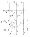
- FIGURE 1 depicts in schematic form a portion of the drive matrix for a flat-panel LCD display as well as test circuitry for testing it by measuring transimmittances.
- the display is organized into rows and columns of pixels, and the drive matrix for a color display includes three electrodes like electrode 12 for each pixel.
- electrode 12 Upon assembly into a complete display, electrode 12 will be disposed on one side of the liquid-crystal material, and an electrode disposed on the other side will be tied to a fixed, common voltage.
- an insulated-gate field-effect transistor Q1 is provided with its source connected to electrode 12 and its drain connected to a common line 14, to which the drains of the transistors that control all of the same-color pixels in the same column are also connected.
- Line 14 will be referred to as a "column line,” a “drain line,” or a “data line.”
- Similar column lines 16 and 18 are connected to the drains of the transistors for different pixel columns or different colors in the same pixel column.
- the gate electrode of transistor Q1 is connected to a row line (or “select line” or “gate line") 20, which conducts enabling signals to the gates of the transistors that control all of the pixels in the same row.
- Row lines 22 and 24 similarly conduct enabling signals to transistors in different rows.
- a drive signal is placed on column line 14. If an enabling voltage is present on row line 20, transistor Q1 forwards this drive signal to electrode 12, causing the desired potential difference across the LCD and thus causing it to assume the desired degree of transparency.
- the same drive voltage is applied to the transistors that control all of the other pixels of the same color in the same column, but none of the others would typically have an enabling voltage on its row line at the same time, so when the drive signal controls electrode 12, it affects that electrode only.
- the purpose of the matrix is to control the transparency of the various pixels.
- the straightforward way to test this function is to connect the matrix to a liquid-crystal panel and observe the result when predetermined select and drive signals are applied.
- the only intended ohmic connection to the pixels occurs through the transistors, there is no alternate location that one can probe to sense the electrode's voltage.
- the transimmittance measurement in the illustrated embodiment is made by employing at least one AC voltage source 26, one or more current detectors 28, 30, and 32, and preferably a variable DC source 34 to bias matrix transistors on and off.
- Source 34 may conveniently be connected in series with the AC source, although it can be separately applied to a different select line.
- the AC source 26 applies an alternating voltage to one of the row or column lines, and a current detector measures the resultant current that flows in another one of the row and column lines.
- That composite source is connected to one of the gate lines 20, 22, and 24, while the current meters are connected to any of the other lines but preferably to at least one of the drain lines 14, 16, and 18. Because capacitances exist between the electrodes and the lines, between transistor terminals, and between the lines themselves, transadmittance results between a port that includes the driven line's terminal and each port whose current a current meter senses. By measuring the various currents, and thereby various transimmittances, it is possible to detect various types of faults.
- the transadmittance between the driven line and column lines downstream of the break will be lower than it otherwise would be, while the transadmittance between the driven line and the column lines upstream of the break will be relatively unaffected.
- the departure from normal can be determined simply by comparing the measured transadmittance with the corresponding transadmittance of a properly operating device. In the alternative, the departure can be determined by observing the differences in the transadmittances that result from operating the variable DC source 34 so as to switch the transistors in the corresponding row between their on and off states.
- the effective capacitance between the row line and the column lines upstream of the break, where the transistors are turned on and off, should change because those transistors short out a series capacitance C EC in the reactive path comprising that capacitance and the capacitance C ER between the row line and the electrode.
- the corresponding capacitances downstream of the break, where the transistors do not turn on and off should change very little.
- the transadmittance should therefore change significantly upstream of the break but not downstream.
- An open drain line can be detected in an analogous manner. If the drain-line measurements that result from the driving of any row line up to a certain point are proper-- e.g., if they change with row-line bias--but those resulting from the driving of row lines beyond that point are not, a drain-line short is the likely cause.
- Another possible defect is an open circuit in the source or drain of a transistor. Either of these defects would reduce the change in transadmittance that results from changing the DC bias voltage.
- a short circuit of this type is a short circuit from the gate line of a transistor to its source or associated LCD electrode. Such a defect would cause a high transconductance when the transistor turns on but not when it turns off.
- a short circuit of this type, as well as a short circuit from the gate to the drain line, does not require measurement of the transadmittance in response to particular AC stimuli; simple DC measurements would be adequate, and the teachings of the present invention, while effective, are not required.
- the teachings of the present invention are required to detect a short from the drain to the source or electrode, however. Such a defect would increase the capacitance that results when the transistors are turned off, and it would result in no difference between on and off capacitances.
- electrode 12 could be shorted to the next gate line, i.e., to a gate line such as line 24, that does not control the transistor associated with that electrode.
- the gate lines not driven are grounded, so an electrode-to-adjacent-gate short causes the capacitance between the electrode's row and column lines to decrease, not increase, when the transistor is turned on.
- the test set-up additionally includes current meters in adjacent row lines, the resultant increased transadmittance to the adjacent row line involved can also be detected.
- Such a test set-up is also beneficial in detecting an electrode-to-electrode short circuit across a gate line.
- Another approach to detecting this type of fault is to drive one gate line with the AC signal but separately drive the adjacent gate line with the DC bias.
- a short circuit from the electrode to the AC-driven gate line then manifests itself as a large current in the drain line that disappears when the DC bias is removed.
- FIGURE 1 depicts a single source 20 and a plurality of current meters 28, 30, and 32.
- the number of simultaneously employed meters in a given application will depend on speed and cost considerations. In principle, there is no reason why all of the lines cannot be monitored simultaneously, and it seems likely that such an arrangement will prove to be beneficial for high-volume production. On the other hand, it is also possible in principle to monitor only one line at a time. In practice, however, this is unlikely to be feasible for production purposes, since tests would have to be run with all combinations of each gate line with most, if not all, of the drain lines and probably with some of the other gate lines. Monitoring only one line at a time therefore is probably adequate only for experimental purposes.
- the method is not limited to the use of only a single AC source at a time.
- different gate lines could be driven with signals of different frequencies, and the meters could simultaneously make separate measurements of the responses at the different frequencies.
- a given meter could thus measure more than one transadmittance at a time.
- the approach of the present invention offers considerable diagnostic information, and the symptoms for many faults can be determined, at least theoretically, by calculation. For many faults, however, the correlation between faults and symptoms will be recognized more readily by experience, possibly through the use of "signature"-type techniques commonly employed in many automatic-test applications.
- FIGURE 2 depicts the AC source 26 and DC source 34 of FIGURE 1. Whereas FIGURE 1 merely shows the AC source 26 as being connected to a ground symbol, FIGURE 2 shows its connection by means of a probe 36 to a (typically grounded) guard ring 38. Although row and column lines such as lines 14 and 20 are to be driven individually in the assembled product, groups of them are typically connected together during the fabrication process by guard conductors, which are used to protect the transistors from damaging potentials, such as those that result from electrostatic discharge during handling. FIGURE 2 depicts only a single guard ring 38, but some testing operations can be made simpler by connecting different subsets of the lines together with different guard conductors.
- connection pad 40 to which contact is made by a probe 42 connected to one end of the series combination of the AC and DC sources 26 and 34.
- the sources have to drive the (typically relatively small) resistance provided by the path 44 between the pad 40 and the guard ring 38.
- Path 44 presents a significant load, so it is desirable for that path to be fabricated with as high a resistance as is feasible. Of course, too high a resistance would defeat the purpose of the guard ring, but a very low resistance loads the voltage source unnecessarily.
- a similar contact pad 46 provides the connection to the column line 14, and a path 48 similar to path 44 provides an electrical connection between the guard ring 38 and that contact pad 46.
- the presence of the guard ring 38 is one of the reasons why it is preferable to make measurements indicative of a transimmittance or other two-port parameter even though the broader aspects of the invention can be performed in principle by measurements indicative of a driving-point (two-terminal) immittance, e.g., by measurements made by imposing the source voltages between terminals 40 and 46 and measuring the source current with no guard connection.
- the guard ring 38 would represent a very high parallel conductance that in most cases would totally mask the parameter of interest.
- the use of driving-point immittances is more practical.
- Probes 50 and 52 provide the connection to the current sensor 30, which FIGURE 2 depicts in more detail.
- the current sensor 30 can include an operational amplifier 54, which is connected to a feedback resistor R f so as to maintain a virtual ground at the column-line contact pad 46; that is, negative feedback causes amplifier 54 to drive its inverting input terminal to a value that nearly equals the voltage on the guard ring 38, and the effect is that the current sensor 30 presents a very-low-impedance path in parallel with connection 48. It is desirable for most of the current from line 14 to pass through the feedback resistor R f rather than through path 48, and this is another reason why it is desirable for those connections to have significant resistance.
- the output of amplifier 54 is a voltage that is proportional to the current that flows through feedback resistor R f and that thus is also proportional to the current that flows in row line 14.
- a phase-sensitive detector 56 measures the in-phase and quadrature components of the voltage across R f , and thus of the current in line 14, by reference to the phase of source 26.
- Control and analysis circuitry 58 typically in the form of a digital computer, receives these measurements, compares them with known good values or other measurements made during the test, as mentioned above, and presents diagnostic or go/no-go results on an appropriate display 60.
- references to port parameters should be understood to include absolute values or individual components as well as complete complex values.
- FIGURE 2 A point of particular interest in FIGURE 2 is that the schematic ground to which source 26 and meter 30 are shown connected in FIGURE 1 are respectively the points at which separate probes 36 and 52 contact the guard ring 38; that is, the ground connections of the two devices to the guard ring 38 are separate; they are not made to a common point that in turn is connected to the guard ring 38.
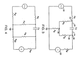
- FIGURE 3 is a schematic diagram that roughly approximates aspects of the test set-up that would result if the source 26 and meter 30 were connected to the ring by a common path.
- the source 26, which has source impedance R s is connected to node 40, which represents the correspondingly numbered contact pad of FIGURE 2.
- a first resistance R A represents the resistance of the connection 44 between the pad 40 and the guard ring 38, which FIGURE 3 represents with a correspondingly numbered node 38.
- the current meter 30, together with its input impedance R m is shown connected to a node 46, which represents the correspondingly numbered pad 46.
- Node 46 is in turn connected to the guard ring 38 by a connection 48 having a resistance R B .
- the unknown of interest i.e., the capacitance between the two pads, is represented in FIGURE 3 by capacitance C X . It is the value of this capacitance C X that provides the diagnostic information of interest.
- the lead-and-contact resistance R g might be kept down to a few ohms, while the values of R A and R B might be one or two orders of magnitude higher.
- the value of C X can be expected to be less than a picofarod.
- the frequency of the source signal will be dictated to some extent by the particular matrix under test. Up to a point, higher frequencies are better, because they result in higher measurable currents for a given (typically low) capacitance, and they permit the measurements to be taken faster. But use of too high a frequency results in shunting of the row- and column-line resistances by other stray capacitances and thus complicating the dependence of the measured transadmittance on the particular capacitances of interest.
- the current seen by the current meter 30 as a result of the conductance path comprising R s , R A , R B , and R m is thus approximately E s R g /R A R B if R m can be ignored; i.e., the transconductance is approximately R g /R A R B .
- this value turns out to be only on the order of 10 ⁇ 5 mhos, it completely swamps the parallel susceptance j2 ⁇ C X of interest unless the source frequency is on the order of 1 MHz or higher, and frequencies that high, as was explained above, would probably not be desirable.
- the FIGURE 3 arrangement is thus disadvantageous because the resultant measurement would be relatively insensitive to the parameter of interest.
- FIGURE 4 represents this circuit schematically.
- FIGURE 4 The labels used for the elements in FIGURE 4 are identical to those used for corresponding elements in FIGURE 3, with the exception that the unitary lead-and-contact resistance R g of FIGURE 3 is replaced in FIGURE 4 with two such resistances, R g1 and R g2 , which represent the lead-and-contact resistances of the separate connections to the guard ring 38.
- Study of FIGURE 4 reveals that, unlike the circuit of FIGURE 3, that of FIGURE 4 provides no parallel current path around the capacitance C X . Consequently, the transimpedance is largely the reactance of C X alone, namely, 1/2 ⁇ fC X , if R A is large with respect to R g2 and R m . Even if it is not so large, the transimpedance is still proportional to that reactance and thus is very sensitive to it. The double-guard approach is therefore preferable in most situations.
- the present invention represents a significant advance in the art.
Landscapes
- Engineering & Computer Science (AREA)
- Physics & Mathematics (AREA)
- General Physics & Mathematics (AREA)
- General Engineering & Computer Science (AREA)
- Computer Hardware Design (AREA)
- Theoretical Computer Science (AREA)
- Tests Of Electronic Circuits (AREA)
- Testing Electric Properties And Detecting Electric Faults (AREA)
- Liquid Crystal (AREA)
Applications Claiming Priority (4)
| Application Number | Priority Date | Filing Date | Title |
|---|---|---|---|
| US51437790A | 1990-04-26 | 1990-04-26 | |
| US514377 | 1990-04-26 | ||
| US07/518,453 US5057775A (en) | 1990-05-04 | 1990-05-04 | Method of testing control matrices for flat-panel displays |
| US518453 | 1990-05-04 |
Publications (1)
| Publication Number | Publication Date |
|---|---|
| EP0455406A1 true EP0455406A1 (fr) | 1991-11-06 |
Family
ID=27058185
Family Applications (1)
| Application Number | Title | Priority Date | Filing Date |
|---|---|---|---|
| EP91303678A Ceased EP0455406A1 (fr) | 1990-04-26 | 1991-04-24 | Méthode pour tester des matrices de commande pour unités de visualisation à écran plat |
Country Status (2)
| Country | Link |
|---|---|
| EP (1) | EP0455406A1 (fr) |
| JP (1) | JPH04351972A (fr) |
Cited By (1)
| Publication number | Priority date | Publication date | Assignee | Title |
|---|---|---|---|---|
| NL9400925A (nl) * | 1993-06-11 | 1995-01-02 | Sharp Kk | Inspectie-inrichting en inspectiewerkwijze voor display-inrichting. |
Citations (3)
| Publication number | Priority date | Publication date | Assignee | Title |
|---|---|---|---|---|
| EP0102296A1 (fr) * | 1982-08-25 | 1984-03-07 | Commissariat à l'Energie Atomique | Procédé de fabrication d'une matrice de composants électroniques |
| EP0272506A2 (fr) * | 1986-12-22 | 1988-06-29 | International Business Machines Corporation | Matrice de transistors en couches minces pour afficheurs à cristaux liquides permettant un test pendant la fabrication, méthode de test, et système d'entrée d'informations comprenant une telle matrice |
| EP0321073A2 (fr) * | 1987-12-18 | 1989-06-21 | Sharp Kabushiki Kaisha | Dispositif d'affichage à cristal liquide |
Family Cites Families (2)
| Publication number | Priority date | Publication date | Assignee | Title |
|---|---|---|---|---|
| JPH0648422B2 (ja) * | 1987-12-01 | 1994-06-22 | 東京エレクトロン九州株式会社 | 液晶表示装置用基板の検査方法 |
| JP2727578B2 (ja) * | 1988-08-08 | 1998-03-11 | 富士通株式会社 | 薄膜トランジスタの特性評価方法 |
-
1990
- 1990-12-28 JP JP2409138A patent/JPH04351972A/ja active Pending
-
1991
- 1991-04-24 EP EP91303678A patent/EP0455406A1/fr not_active Ceased
Patent Citations (3)
| Publication number | Priority date | Publication date | Assignee | Title |
|---|---|---|---|---|
| EP0102296A1 (fr) * | 1982-08-25 | 1984-03-07 | Commissariat à l'Energie Atomique | Procédé de fabrication d'une matrice de composants électroniques |
| EP0272506A2 (fr) * | 1986-12-22 | 1988-06-29 | International Business Machines Corporation | Matrice de transistors en couches minces pour afficheurs à cristaux liquides permettant un test pendant la fabrication, méthode de test, et système d'entrée d'informations comprenant une telle matrice |
| EP0321073A2 (fr) * | 1987-12-18 | 1989-06-21 | Sharp Kabushiki Kaisha | Dispositif d'affichage à cristal liquide |
Cited By (1)
| Publication number | Priority date | Publication date | Assignee | Title |
|---|---|---|---|---|
| NL9400925A (nl) * | 1993-06-11 | 1995-01-02 | Sharp Kk | Inspectie-inrichting en inspectiewerkwijze voor display-inrichting. |
Also Published As
| Publication number | Publication date |
|---|---|
| JPH04351972A (ja) | 1992-12-07 |
Similar Documents
| Publication | Publication Date | Title |
|---|---|---|
| US5057775A (en) | Method of testing control matrices for flat-panel displays | |
| US5363037A (en) | Method and apparatus for testing LCD panel array | |
| US6566902B2 (en) | Liquid crystal display device for testing signal line | |
| US8536892B2 (en) | System for testing transistor arrays in production | |
| US5428300A (en) | Method and apparatus for testing TFT-LCD | |
| JP2672260B2 (ja) | Tft−lcdの検査方法 | |
| US5243272A (en) | Method of testing control matrices employing distributed source return | |
| EP0455406A1 (fr) | Méthode pour tester des matrices de commande pour unités de visualisation à écran plat | |
| JP2506840B2 (ja) | アクティブマトリックスアレイの検査方法 | |
| KR100471782B1 (ko) | 액정표시장치의불량검출방법 | |
| JP3268102B2 (ja) | アレイ基板 | |
| JP3290602B2 (ja) | 液晶表示装置の検査方法および液晶表示装置 | |
| JPH0659283A (ja) | Tft−lcdの検査方法及びその装置 | |
| JP3179288B2 (ja) | 配線基板の検査装置および検査方法 | |
| JPH07287247A (ja) | アクティブマトリクス基板の検査方法 | |
| JP3014915B2 (ja) | 多面取り薄膜トランジスタアレイ基板及びその検査方法 | |
| JP3068617B1 (ja) | リ―ク防止機能を有する画素容量検査装置 | |
| JP3021738U (ja) | Tft−lcdの検査装置 | |
| JP3121038B2 (ja) | Lcd基板上のtft画素の検査方法及び検査装置 | |
| JP3309083B2 (ja) | 画素容量検査装置 | |
| JPH086047A (ja) | アクティブマトリクス基板の検査方法 | |
| JP2629213B2 (ja) | アクティブマトリックスアレイの検査方法および検査装置 | |
| JPH0711639B2 (ja) | 薄膜トランジスタアレイの欠陥検査方法 | |
| JP2607447Y2 (ja) | 表示体駆動用半導体装置 | |
| JP3505423B2 (ja) | 液晶セルおよびその検査方法 |
Legal Events
| Date | Code | Title | Description |
|---|---|---|---|
| PUAI | Public reference made under article 153(3) epc to a published international application that has entered the european phase |
Free format text: ORIGINAL CODE: 0009012 |
|
| AK | Designated contracting states |
Kind code of ref document: A1 Designated state(s): DE FR GB IT |
|
| 17P | Request for examination filed |
Effective date: 19920414 |
|
| 17Q | First examination report despatched |
Effective date: 19930922 |
|
| STAA | Information on the status of an ep patent application or granted ep patent |
Free format text: STATUS: THE APPLICATION HAS BEEN REFUSED |
|
| 18R | Application refused |
Effective date: 19940911 |