EP0455441A2 - Culasse de déviation - Google Patents
Culasse de déviation Download PDFInfo
- Publication number
- EP0455441A2 EP0455441A2 EP91303835A EP91303835A EP0455441A2 EP 0455441 A2 EP0455441 A2 EP 0455441A2 EP 91303835 A EP91303835 A EP 91303835A EP 91303835 A EP91303835 A EP 91303835A EP 0455441 A2 EP0455441 A2 EP 0455441A2
- Authority
- EP
- European Patent Office
- Prior art keywords
- coils
- deflection
- horizontal
- auxiliary
- coil
- Prior art date
- Legal status (The legal status is an assumption and is not a legal conclusion. Google has not performed a legal analysis and makes no representation as to the accuracy of the status listed.)
- Withdrawn
Links
Images


Classifications
-
- H—ELECTRICITY
- H01—ELECTRIC ELEMENTS
- H01J—ELECTRIC DISCHARGE TUBES OR DISCHARGE LAMPS
- H01J29/00—Details of cathode-ray tubes or of electron-beam tubes of the types covered by group H01J31/00
- H01J29/003—Arrangements for eliminating unwanted electromagnetic effects, e.g. demagnetisation arrangements, shielding coils
-
- H—ELECTRICITY
- H01—ELECTRIC ELEMENTS
- H01J—ELECTRIC DISCHARGE TUBES OR DISCHARGE LAMPS
- H01J29/00—Details of cathode-ray tubes or of electron-beam tubes of the types covered by group H01J31/00
- H01J29/46—Arrangements of electrodes and associated parts for generating or controlling the ray or beam, e.g. electron-optical arrangement
- H01J29/70—Arrangements for deflecting ray or beam
- H01J29/72—Arrangements for deflecting ray or beam along one straight line or along two perpendicular straight lines
- H01J29/76—Deflecting by magnetic fields only
-
- H—ELECTRICITY
- H01—ELECTRIC ELEMENTS
- H01J—ELECTRIC DISCHARGE TUBES OR DISCHARGE LAMPS
- H01J2229/00—Details of cathode ray tubes or electron beam tubes
- H01J2229/0007—Elimination of unwanted or stray electromagnetic effects
- H01J2229/0015—Preventing or cancelling fields leaving the enclosure
- H01J2229/0023—Passive means
Definitions
- This invention relates to deflection yokes for devices such as television receivers or CRT display units, and particularly concerns reducing unnecessary radiant magnetic fields.
- deflection yokes are the main sources.
- Magnetic field leakage from deflection yokes other than substantially axial of CRTs can be shielded, but it is not practical effectively to shield magnetic field leakage from CRT faces (as they cannot be covered obscuringly).
- Recently, one proposal to offset magnetic field leakage, and reduce unnecessary radiation, has been by adding to the deflection yoke a pair of saddle- shaped horizontal auxiliary coils 13a and 13b, or a pair of horizontal coils made by winding wire around a bobbins for a magnetic field generation in opposition to leakage of magnetic field from the horizontal deflection yoke.
- a purpose of this invention is to provide a deflection yoke which reduces unnecessary radiant magnetic field generated therein and allows easy production of horizontal auxiliary coils therefor, and at the same time which does not make large space requirements, and to which the horizontal auxiliary coil can easily be mounted.
- this invention provides a deflection yoke comprising horizontal deflection coils, and auxiliary coils associated with the horizontal deflection coils adjacent to and following curving of forward curved parts of the horizontal deflection coils, the auxiliary coils being electrically connected so that horizontal coil deflection current flowing therethrough augments magnetic field produced by said curved parts of the horizontal deflection coils.
- a typical deflection yoke has a horizontal deflection coil set including a pair of saddle-shaped coils, and a pair of void-core type of horizontal auxiliary coils of saddle form are received by a coil holder, and the coil holder receiving said horizontal auxiliary coils is located at a position where said horizontal auxiliary coils span a forward curved part of each of said pair of horizontal deflection coils in a manner allowing the coil holder to be mounted and demounted.
- Said horizontal auxiliary coils will be connected to said horizontal deflection coil set and horizontal deflection current flows having directions producing more intense magnetic fields at said forward curved parts of said horizontal deflection coils.
- the coil holder can be a unitary or multipart unit in the form of circular ring assisting mounting and demounting the coil holder at a periphery of a forward opening part of the aforesaid horizontal deflection coil set.
- the horizontal auxiliary coils can be made by winding litz wire. Alternatively, they can be made by winding results of twisting or simply bundling several small-diameter insulating wires.
- horizontal deflection current flow in the horizontal auxiliary coils that intensifies magnetic fields set each forward part of the horizontal deflection coils and a composite magnetic field generated by each of the forward curved parts and the horizontal auxiliary coils serve to allow offsetting magnetic field leaked from said horizontal deflection coil in a forward direction of the CRT screen, so that unnecessary radiant magnetic field is reduced.
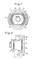
- a deflection yoke 1 has saddle- shaped horizontal deflection coils 2a and 2b, saddle- shaped vertical deflection coils 3a and 3b, and a core 4, together with a coil separator 5, and a horizontal auxiliary coil unit 6 in which horizontal auxiliary coils are in a coil holder 8 of circular ring structure.
- Fig. 3 and Fig. 4 show a saddle-shaped void-core coil 7 as said horizontal auxiliary coil.
- the void-core coil 7 is of similar form to curved medial, outer or forward parts of the horizontal deflection coils with an arcuate extent ⁇ (Fig. 3) and transverse extent l (Fig. 4).
- the coil 7 can be of self welding wire with a welding layer of a material such as polyamide around an insulation layer of a material such as polyurethane or polyester.
- the coil holder 8 is shown as a circular ring holding the pair of coils 7a and 7b diametrically opposite each other.
- the coil holder 8 has formations at 8a, indicated as recessed parts, to locate the coils 7a and 7b, indicated by one long edge thereof, and affording supports 8b for their ends.
- Resilient or elastic claws 8c allow easy attachment of the coil holder 8 to the coil separator 5 adjacent medial front parts of the horizontal deflection coils 2a and 2b, respectively.
- insulating cover 9 is shown over the supports 8b.
- the insulation cover 9 is cylindrical and has resilient lugs 9a and 9b, see Fig. 9 and Fig. 10, to complete the horizontal auxiliary coil unit 6.
- such horizontal auxiliary coil unit 6 is engagable with the coil separator 5 to be peripheral of the front of the horizontal deflection coils 2a and 2b using the claws 8c.
- the pair of coreless coils 7a and 7b are then located astride the curved parts 12a and 12b at top and bottom of a vertical axis through the horizontal deflection coils 2a and 2b.
- the pair of coils 7a and 7b can be connected in parallel or in series with the horizontal deflection coils 2a and 2b, and it is possible for current flow to be in a direction intensifying the magnetic field at curved parts 12a and 12b of the horizontal deflection coils 2a and 2b, as shown in Fig. 13.
- its magnetic field at the forward opening of its pair of saddle-shaped horizontal deflection coils 2a and 2b is of a composite nature, as shown in Fig. 11, including a magnetic field Hy1 generated by the main deflecting coil 10 and a magnetic field Hy2 generated at the curved parts 12a and 12b.
- the curved parts 12a and 12b can serve to reduce leakage 11 of magnetic field in the direction of the CRT screen and the front opening of the horizontal deflection coils, as shown in Fig. 12.
- the magnetic field 11 leaked away from the CRT screen and out of sides of the front opening of the horizontal deflection coils 2a and 2b can thus be reduced.
- deflection yokes hereof is to intensify magnetic field strength at forward curved parts of horizontal deflection coils compared with that generated by a conventional horizontal deflection coil. Accordingly, a length L of a coil can be shorter than is conventional, indeed satisfactory operation can be achieved with a length which is around half.
- the coil holder 8 may not be unitary, i.e. can be of multipart type.
- the coils 7a and 7b can be made of bundled and twisted litz wires, or of small-diameter insulated wires, or made by simply winding bundled wires.
- Fig. 14 and Fig. 15 show prior proposals for a deflection yoke 1′ having additional saddle-shaped auxiliary horizontal coils 13a and 13b, or a pair of bobbin-wind coils 14a and 14b, operative to generate a magnetic field opposite or in reverse to the leakage magnetic field of the horizontal deflection yoke 1′.
- auxiliary coils of saddle-shaped coreless type can easily be mounted and demounted.
- configuration of such auxiliary coils is similar to that of front curved parts of the horizontal deflection coils, which saves space.
- locating a pair of auxiliary coils to enhance the magnetic field at forward curved parts of the deflection coils means unnecessary radiant magnetic field in the direction of the tube face can be reduced very efficiently.
Landscapes
- Physics & Mathematics (AREA)
- Electromagnetism (AREA)
- Video Image Reproduction Devices For Color Tv Systems (AREA)
Applications Claiming Priority (2)
| Application Number | Priority Date | Filing Date | Title |
|---|---|---|---|
| JP1990045758U JPH0724773Y2 (ja) | 1990-04-28 | 1990-04-28 | 偏向ヨーク |
| JP45758/90 | 1990-04-28 |
Publications (2)
| Publication Number | Publication Date |
|---|---|
| EP0455441A2 true EP0455441A2 (fr) | 1991-11-06 |
| EP0455441A3 EP0455441A3 (en) | 1993-05-19 |
Family
ID=12728198
Family Applications (1)
| Application Number | Title | Priority Date | Filing Date |
|---|---|---|---|
| EP19910303835 Withdrawn EP0455441A3 (en) | 1990-04-28 | 1991-04-26 | A deflection yoke |
Country Status (3)
| Country | Link |
|---|---|
| US (1) | US5220241A (fr) |
| EP (1) | EP0455441A3 (fr) |
| JP (1) | JPH0724773Y2 (fr) |
Cited By (1)
| Publication number | Priority date | Publication date | Assignee | Title |
|---|---|---|---|---|
| DE4344268A1 (de) * | 1992-12-30 | 1994-07-07 | Murata Manufacturing Co | Ablenkspulenjoch |
Families Citing this family (5)
| Publication number | Priority date | Publication date | Assignee | Title |
|---|---|---|---|---|
| JPH038293Y2 (fr) * | 1984-10-25 | 1991-02-28 | ||
| US5355107A (en) * | 1991-12-06 | 1994-10-11 | Samsung Electron Devices Co., Ltd. | Deflection yoke with leaking magnetic field prevention coils |
| JPH087791A (ja) * | 1994-06-17 | 1996-01-12 | Sony Corp | 漏洩磁束キャンセル装置 |
| US5675213A (en) * | 1995-11-16 | 1997-10-07 | Chunghwa Picture Tubes, Ltd | Cathode ray tube deflection yoke with reduced electric field radiation from terminal pins of printed circuit board on yoke |
| JP3339045B2 (ja) * | 1996-01-25 | 2002-10-28 | 日本ビクター株式会社 | 偏向ヨーク |
Family Cites Families (8)
| Publication number | Priority date | Publication date | Assignee | Title |
|---|---|---|---|---|
| JPS5543701A (en) * | 1978-09-20 | 1980-03-27 | Toshiba Corp | Color image receiving tube |
| NL8300032A (nl) * | 1983-01-06 | 1984-08-01 | Philips Nv | Inrichting voor het weergeven van televisiebeelden en afbuigeenheid daarvoor. |
| IN167955B (fr) * | 1986-03-27 | 1991-01-12 | Nokia Data Systems | |
| NL8701109A (nl) * | 1987-05-11 | 1988-12-01 | Philips Nv | Beeldweergeefinrichting met strooiveld-compensatiemiddelen. |
| US4992697A (en) * | 1988-02-01 | 1991-02-12 | U.S. Philips Corporation | Picture display device with magnetizable core means comprising compensation coils |
| JPH01225046A (ja) * | 1988-03-04 | 1989-09-07 | Hitachi Ltd | 偏向ヨーク |
| JP2676018B2 (ja) * | 1988-12-19 | 1997-11-12 | 株式会社日立製作所 | 偏向ヨーク,偏向ヨーク用補助コイル及び画像表示装置 |
| KR920001582Y1 (ko) * | 1989-12-23 | 1992-03-05 | 삼성전관 주식회사 | 편향요크 |
-
1990
- 1990-04-28 JP JP1990045758U patent/JPH0724773Y2/ja not_active Expired - Lifetime
-
1991
- 1991-04-22 US US07/689,225 patent/US5220241A/en not_active Expired - Fee Related
- 1991-04-26 EP EP19910303835 patent/EP0455441A3/en not_active Withdrawn
Cited By (1)
| Publication number | Priority date | Publication date | Assignee | Title |
|---|---|---|---|---|
| DE4344268A1 (de) * | 1992-12-30 | 1994-07-07 | Murata Manufacturing Co | Ablenkspulenjoch |
Also Published As
| Publication number | Publication date |
|---|---|
| JPH0724773Y2 (ja) | 1995-06-05 |
| JPH046152U (fr) | 1992-01-21 |
| EP0455441A3 (en) | 1993-05-19 |
| US5220241A (en) | 1993-06-15 |
Similar Documents
| Publication | Publication Date | Title |
|---|---|---|
| US4853588A (en) | Deflection yoke apparatus with means for reducing unwanted radiation | |
| JP2965073B2 (ja) | 画像表示装置 | |
| KR0141699B1 (ko) | 화상 디스플레이 장치 | |
| JPH02165546A (ja) | 偏向ヨーク,偏向ヨーク用補助コイル及び画像表示装置 | |
| EP0327161B1 (fr) | Dispositif de reproduction d'image comportant un noyau magnétisable muni de bobinages de compensation | |
| KR960011734B1 (ko) | 영상 표시 장치 | |
| US5220241A (en) | Deflection yoke having horizontal auxiliary coils for reducing unnecessary radiant magnetic field | |
| KR910001513B1 (ko) | 텔레비젼 화상 표시 장치 | |
| US5485054A (en) | Display tube having a deflection coil support and an auxiliary deflection coil support | |
| EP0568783A1 (fr) | Tube à rayons cathodiques avec bobine de déviation | |
| KR960000348B1 (ko) | 라인 스트레이 필드를 보상하는 수단을 구비한 화상 표시 장치 | |
| JPH0747785Y2 (ja) | 偏向ヨーク装置 | |
| EP0540096B1 (fr) | Appareil à collier de déviation muni de moyens pour réduire les champs magnetiques de fuites | |
| JPH0624100B2 (ja) | 偏向ヨ−ク装置 | |
| JPH01225046A (ja) | 偏向ヨーク | |
| US5432492A (en) | Deflection yoke apparatus with auxiliar coils to compensensate magnetic leakage | |
| KR970008294A (ko) | 다이나믹컨버전스장치를 구비한 컬러음극선관 및 이것을 사용한 컬러표시장치 | |
| KR950009660Y1 (ko) | 음극선관의 편향요크 | |
| JP3352520B2 (ja) | 偏向ヨーク及びこれを用いた陰極線管 | |
| JPH0622103B2 (ja) | 偏向ヨ−ク装置 | |
| JPH0646546B2 (ja) | 偏向ヨ−ク装置 | |
| JPH0638327B2 (ja) | 偏向ヨ−ク装置 | |
| JP2000113833A (ja) | 偏向ヨーク | |
| JPH0563892B2 (fr) | ||
| JPH0536361A (ja) | 白黒デイスプレイモニタ用偏向ヨーク |
Legal Events
| Date | Code | Title | Description |
|---|---|---|---|
| PUAI | Public reference made under article 153(3) epc to a published international application that has entered the european phase |
Free format text: ORIGINAL CODE: 0009012 |
|
| AK | Designated contracting states |
Kind code of ref document: A2 Designated state(s): DE FR GB |
|
| PUAL | Search report despatched |
Free format text: ORIGINAL CODE: 0009013 |
|
| AK | Designated contracting states |
Kind code of ref document: A3 Designated state(s): DE FR GB |
|
| 17P | Request for examination filed |
Effective date: 19930628 |
|
| 17Q | First examination report despatched |
Effective date: 19941227 |
|
| STAA | Information on the status of an ep patent application or granted ep patent |
Free format text: STATUS: THE APPLICATION IS DEEMED TO BE WITHDRAWN |
|
| 18D | Application deemed to be withdrawn |
Effective date: 19990703 |