EP0455454B2 - Pneu à carcasse radiale - Google Patents
Pneu à carcasse radiale Download PDFInfo
- Publication number
- EP0455454B2 EP0455454B2 EP91303864A EP91303864A EP0455454B2 EP 0455454 B2 EP0455454 B2 EP 0455454B2 EP 91303864 A EP91303864 A EP 91303864A EP 91303864 A EP91303864 A EP 91303864A EP 0455454 B2 EP0455454 B2 EP 0455454B2
- Authority
- EP
- European Patent Office
- Prior art keywords
- strip
- cords
- breaker
- width
- band
- Prior art date
- Legal status (The legal status is an assumption and is not a legal conclusion. Google has not performed a legal analysis and makes no representation as to the accuracy of the status listed.)
- Expired - Lifetime
Links
- 238000004804 winding Methods 0.000 claims description 20
- 239000011295 pitch Substances 0.000 claims description 19
- 229920001971 elastomer Polymers 0.000 claims description 12
- 239000005060 rubber Substances 0.000 claims description 12
- 239000011324 bead Substances 0.000 claims description 8
- 239000000835 fiber Substances 0.000 claims description 7
- 244000043261 Hevea brasiliensis Species 0.000 claims description 5
- 239000004677 Nylon Substances 0.000 claims description 5
- 150000001875 compounds Chemical class 0.000 claims description 5
- 229920003052 natural elastomer Polymers 0.000 claims description 5
- 229920001194 natural rubber Polymers 0.000 claims description 5
- 229920001778 nylon Polymers 0.000 claims description 5
- 229920003048 styrene butadiene rubber Polymers 0.000 claims description 4
- 230000003014 reinforcing effect Effects 0.000 description 6
- 238000000034 method Methods 0.000 description 4
- 230000002787 reinforcement Effects 0.000 description 4
- 238000010586 diagram Methods 0.000 description 3
- 230000000694 effects Effects 0.000 description 3
- 229910000831 Steel Inorganic materials 0.000 description 2
- XLOMVQKBTHCTTD-UHFFFAOYSA-N Zinc monoxide Chemical compound [Zn]=O XLOMVQKBTHCTTD-UHFFFAOYSA-N 0.000 description 2
- 239000004760 aramid Substances 0.000 description 2
- 229920003235 aromatic polyamide Polymers 0.000 description 2
- 239000000463 material Substances 0.000 description 2
- 229920000728 polyester Polymers 0.000 description 2
- 239000010959 steel Substances 0.000 description 2
- 241001137251 Corvidae Species 0.000 description 1
- 229920000297 Rayon Polymers 0.000 description 1
- 235000021355 Stearic acid Nutrition 0.000 description 1
- 239000002174 Styrene-butadiene Substances 0.000 description 1
- NINIDFKCEFEMDL-UHFFFAOYSA-N Sulfur Chemical compound [S] NINIDFKCEFEMDL-UHFFFAOYSA-N 0.000 description 1
- 230000001154 acute effect Effects 0.000 description 1
- 239000003963 antioxidant agent Substances 0.000 description 1
- 230000003078 antioxidant effect Effects 0.000 description 1
- 239000006229 carbon black Substances 0.000 description 1
- 238000010276 construction Methods 0.000 description 1
- 238000007796 conventional method Methods 0.000 description 1
- 230000003247 decreasing effect Effects 0.000 description 1
- 239000011521 glass Substances 0.000 description 1
- 230000004048 modification Effects 0.000 description 1
- 238000012986 modification Methods 0.000 description 1
- QIQXTHQIDYTFRH-UHFFFAOYSA-N octadecanoic acid Chemical compound CCCCCCCCCCCCCCCCCC(O)=O QIQXTHQIDYTFRH-UHFFFAOYSA-N 0.000 description 1
- OQCDKBAXFALNLD-UHFFFAOYSA-N octadecanoic acid Natural products CCCCCCCC(C)CCCCCCCCC(O)=O OQCDKBAXFALNLD-UHFFFAOYSA-N 0.000 description 1
- 235000015108 pies Nutrition 0.000 description 1
- 239000002964 rayon Substances 0.000 description 1
- 230000000717 retained effect Effects 0.000 description 1
- 238000000926 separation method Methods 0.000 description 1
- 239000008117 stearic acid Substances 0.000 description 1
- 229910052717 sulfur Inorganic materials 0.000 description 1
- 239000011593 sulfur Substances 0.000 description 1
- 239000011787 zinc oxide Substances 0.000 description 1
Images




Classifications
-
- B—PERFORMING OPERATIONS; TRANSPORTING
- B60—VEHICLES IN GENERAL
- B60C—VEHICLE TYRES; TYRE INFLATION; TYRE CHANGING; CONNECTING VALVES TO INFLATABLE ELASTIC BODIES IN GENERAL; DEVICES OR ARRANGEMENTS RELATED TO TYRES
- B60C9/00—Reinforcements or ply arrangement of pneumatic tyres
- B60C9/18—Structure or arrangement of belts or breakers, crown-reinforcing or cushioning layers
- B60C9/20—Structure or arrangement of belts or breakers, crown-reinforcing or cushioning layers built-up from rubberised plies each having all cords arranged substantially parallel
- B60C9/22—Structure or arrangement of belts or breakers, crown-reinforcing or cushioning layers built-up from rubberised plies each having all cords arranged substantially parallel the plies being arranged with all cords disposed along the circumference of the tyre
- B60C9/2204—Structure or arrangement of belts or breakers, crown-reinforcing or cushioning layers built-up from rubberised plies each having all cords arranged substantially parallel the plies being arranged with all cords disposed along the circumference of the tyre obtained by circumferentially narrow strip winding
-
- B—PERFORMING OPERATIONS; TRANSPORTING
- B60—VEHICLES IN GENERAL
- B60C—VEHICLE TYRES; TYRE INFLATION; TYRE CHANGING; CONNECTING VALVES TO INFLATABLE ELASTIC BODIES IN GENERAL; DEVICES OR ARRANGEMENTS RELATED TO TYRES
- B60C9/00—Reinforcements or ply arrangement of pneumatic tyres
- B60C9/18—Structure or arrangement of belts or breakers, crown-reinforcing or cushioning layers
- B60C9/20—Structure or arrangement of belts or breakers, crown-reinforcing or cushioning layers built-up from rubberised plies each having all cords arranged substantially parallel
- B60C9/22—Structure or arrangement of belts or breakers, crown-reinforcing or cushioning layers built-up from rubberised plies each having all cords arranged substantially parallel the plies being arranged with all cords disposed along the circumference of the tyre
- B60C2009/2219—Structure or arrangement of belts or breakers, crown-reinforcing or cushioning layers built-up from rubberised plies each having all cords arranged substantially parallel the plies being arranged with all cords disposed along the circumference of the tyre with a partial zero degree ply at the belt edges - edge band
-
- Y—GENERAL TAGGING OF NEW TECHNOLOGICAL DEVELOPMENTS; GENERAL TAGGING OF CROSS-SECTIONAL TECHNOLOGIES SPANNING OVER SEVERAL SECTIONS OF THE IPC; TECHNICAL SUBJECTS COVERED BY FORMER USPC CROSS-REFERENCE ART COLLECTIONS [XRACs] AND DIGESTS
- Y10—TECHNICAL SUBJECTS COVERED BY FORMER USPC
- Y10T—TECHNICAL SUBJECTS COVERED BY FORMER US CLASSIFICATION
- Y10T152/00—Resilient tires and wheels
- Y10T152/10—Tires, resilient
- Y10T152/10495—Pneumatic tire or inner tube
- Y10T152/10765—Characterized by belt or breaker structure
- Y10T152/10783—Reinforcing plies made up from wound narrow ribbons
-
- Y—GENERAL TAGGING OF NEW TECHNOLOGICAL DEVELOPMENTS; GENERAL TAGGING OF CROSS-SECTIONAL TECHNOLOGIES SPANNING OVER SEVERAL SECTIONS OF THE IPC; TECHNICAL SUBJECTS COVERED BY FORMER USPC CROSS-REFERENCE ART COLLECTIONS [XRACs] AND DIGESTS
- Y10—TECHNICAL SUBJECTS COVERED BY FORMER USPC
- Y10T—TECHNICAL SUBJECTS COVERED BY FORMER US CLASSIFICATION
- Y10T152/00—Resilient tires and wheels
- Y10T152/10—Tires, resilient
- Y10T152/10495—Pneumatic tire or inner tube
- Y10T152/10765—Characterized by belt or breaker structure
- Y10T152/1081—Breaker or belt characterized by the chemical composition or physical properties of elastomer or the like
Definitions
- the present invention relates to a belted radial ply tyre, which is improved in Radial Runout (RRO) and is able to improve productivity.
- RRO Radial Runout
- a radial tyre is provided with a belt reinforcement comprising a breaker A and a band or bandage B, wherein the band cords are generally laid parallel to the circumferential direction of the tyre and contrarily, the breaker cords are inclined with respect to the circumferential direction.
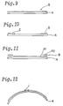
- FIG. 9 shows a full band B composed of a full width ply.
- Figure 10 shows an edge band B composed of a pair of edge pies.
- Figure 11 shows a combination band B composed of a full width ply b1 and a pair of edge plies b2.
- the edge plies are effective in increasing the hoop force at the breaker edges, and accordingly effective in preventing ply edge looseness and separation.
- such a band ply is formed by winding a ply material having the same width as its finishing width, around the carcass, and the ends of the ply are overlapped each for a certain amount at a joint J shown in Figure 12. Accordingly, the thickness and rigidity are increased at the joint J, and the RRO (Radial Runout) of the tyre is increased, and further, the tyre uniformity is disturbed.
- a jointless band may be used, but as shown in Figure 16, to form an edge ply at each edge of a breaker, when a strip T is wound separately at each breaker edge, since the number of windings or turns in each ply is small and both ends of the strip are free, the wound strip is liable to be loosened and to move during the tyre vulcanising process due to the increased cord tension, and accordingly the finished ply has an uneven thickness distribution which increases RRO, and spoils tyre uniformity.
- JITSUYO-KOKAI Japanese Utility-Model Publication
- No 61-15604 discloses a band B shown in Figure 13, wherein a strip T is wound spirally at regular pitches from one edge to the other edge of a breaker, while slightly overlapping the adjacent edges thereof. Accordingly, the hoop effect is not enhanced at the breaker edge regions at which a strong hooping force is required.
- a band B having a double layered structure at the edge of a breaker A like the band B shown in Figure 11 is disclosed, wherein a strip T including reinforcing cords of 1 to 8 in number is wound, while traversing a breaker A as shown in Figure 14.
- the traversing direction is changed at least twice as indicated by the arrows in Figure 14 to wind the strip around the previously wound portion thereof.
- the allowed Japanese Patent Publication (KOUKOKU) No 1-278803 (corresponding to EP-A-0 333 628) discloses a band B, also formed by winding a strip T around a breaker A, wherein the strip is overlapped as shown in Figure 15. In a central region, the overlap is 50% of the strip width and the overlap is increased to 75% in side regions. Accordingly, the band has a double layered structure even in the central region, which results in an excessive increase in the hooping force in the central region as well as a decrease in cornering power. Further the tyre weight increases.
- a tyre having a band formed by winding a strip around a breaker to form a layer overlapped in the side parts is disclosed by Patent Publication DE-3629955.
- a radial tyre comprises a carcass extending between bead portions through sidewall portions and a tread region comprising at least one ply of radially arranged cords turned up around bead cores, and a belt disposed radially outside the carcass and inside the tread and composed of a breaker and a band, said breaker comprising at least two plies of cords inclined with respect to the tyre equator so that the cords in each ply cross the cords in the next ply, and said band being disposed on the radially outer side of the breaker and comprising a strip of parallel organic fibre cords embedded in a topping rubber which strip is wound spirally and continuously around the breaker from its one edge to the other edge, the winding pitches of the strip in the side regions of the breaker being substantially a half of the strip width, and the pitches in the central region being not less than the strip width, wherein the width of the central region is 1/3 to 1/1.5 times the breaker width, characterised
- a radial tyre 1 comprises a pair of bead cores 5 disposed one in each bead portion 4 of the tyre, a carcass 6 extending between the bead portions 4 through a tread portion 2 and sidewall portions 3 of the tyre and turned up around the bead cores 5 from the inside to the outside of the tyre.
- the tread 2 is disposed radially outside the carcass, and a belt reinforcement is disposed between the carcass and the tread and comprises a breaker 7 disposed radially outside the carcass 6 and a band 9 disposed on the radially outer side of the breaker 7.
- the carcass 6 is composed of at least one ply of cords arranged radially at 70 to 90 degrees with respect to the tyre equator.
- the breaker 7 in this embodiment comprises two plies 7a and 7b of parallel cords.
- the radially inner ply 7a has an axial width substantially equal to the tread width between the edges (a) of the tread 2.
- the radially outer ply 7b has a narrower width than the inner ply 7a. Therefore, the inner ply 7a is effectively provided with projecting portions 10 from the edges b of the outer ply 7b to the edges c1 and c2 of the breaker assembly.
- the breaker plies 7a and 7b are made of high modulus cords, e.g. steel cords,, aromatic polyamide cords or the like, and the cords in each ply are arranged parallel to each other and inclined at acute angles with respect to the tyre equator C to cross the cords in the next ply, so as not to provide directional characteristics in the tyre from the breaker and to provide the necessary reinforcing effect and hoop effect of the breaker.
- high modulus cords e.g. steel cords,, aromatic polyamide cords or the like
- each ply 7a and 7b is formed by a conventional method, that is by winding around a carcass a ply material slip having the same width as the finished ply width.
- the band 10 is formed by winding spirally and continuously a narrow band strip T around the breakers 7a,7b.
- the winding is from one edge to the other edge thereof as shown in the embodiment in the Figures from the left edge c1 to the right edge c2 of the inner wide ply 7a of the breaker 7.
- the band strip T comprises reinforcing cords 12 which are laid parallel to each other, and a topping rubber 13 in which the reinforcing cords 12 are embedded.
- the cords are arranged in the widthwise direction of the strip in a line and spaced apart by a small distance.
- the spiral winding pitch P of the band strip T is changed between a central region 7A and side regions 7B, wherein the central region 7A is centred on the tyre equator C and the width thereof is 1/3 to 1/1.5 times the full breaker width which is the axial width between the edges c1 and c2 of the inner wide ply 7a.
- the spiral pitches PB are such that the spaces 1 between the axially adjacent parts of the wound strip T are set in the range of 30 to 100mm.
- the spiral pitches PA are set at a substantially 1/2 width of the band strip width w, which pitches PA are smaller than the pitches PB in the central region, where "substantially 1/2 width” means W/2 plus or minus 50%. Accordingly an edge band like that shown in Figure 10 is formed.
- the spiral pitches P are changed only in a transitional region which is formed between the central region 7A and each of the side regions 7B.
- the band 9 covers the whole width of the side regions 7B of the breaker 7. Accordingly, at the edges c1 and c1 of the breaker, the strip T is wound completely to the edges c1 and c2, that is the first turn and the last turn of the strip are made along the respective edges.
- the strip T can be protruded from the edges c1 and c2 by, for example, a half strip width or the pitch PA, and the protruding portions 15 (as shown in Figure 5) cut off, but they may be retained uncut.
- the number of reinforcing cords in the strip T is in the range of 10 to 25, whereby the strip has a suitable width for the winding work which allows a smooth change in the winding pitches. If the number is less than 10, the width w of the strip T is too small, and the winding work efficiency is poor, and further the dimensional accuracy of the band is liable to be lost. If the number is more than 25, the width w is too large, and the strip is likely to be creased in the above-mentioned transitional regions, which results in poor working efficiency.
- the width w of the strip T is in the range of 10 to 30mm, preferably 12 to 25mm.
- the thickness t of the strip is set in the range of 0.5 to 1.0mm.
- organic fibre cords having a tensile strength of not more than 100 kgf/sq.mm for example nylon cords, polyester cords or the like, are used for the reinforcing cords 12.
- nylon-cords which have a heat shrinking characteristic are preferably used because the hoop force of the band to the breaker 7 is then increased in the tyre vulcanising process.
- 66-nylon cords whose cord thickness, elongation specified by JIS-L1017, and elastic modulus are respectively 1000d/2 to 1500d/2, 8 to 10%, and 4 to 10 x 10 4 kgf/sq.cm are preferably used.
- topping rubber of the strip various rubber compounds may be used, but a compound containing 30 to 95 parts by weight of natural rubber (NR) and 5 to 70 parts by weight of styrene-butadiene rubber (SBR) is preferably used because such a compound has good strength and durability against repeated deformation, and the temperature rise due to the hysteresis loss in use of the tyre is well controlled.
- NR 70 natural rubber
- SBR styrene-butadiene rubber
- Figure 3 shows a modification of the band 9, in which the spiral pitches PA in the central region 7A are decreased to a value corresponding to the strip width w, while the pitches PB in the side regions 7B are kept unchanged at a half width w/2. In this case, therefore, a double layered structure is formed in the side regions 7B, and a single continuous layer structure is formed in the central regions 7A.
- the bands 9 are combined with the breaker 7 composed of only the cut-end plies 7a and 7b of which edges are cut and left as they are.
- the band 9 can be combined with a breaker 7 including at least one folded ply 7c the edges of which are folded radially outwardly or radially inwardly as shown in Figure 4.
- it can be combined with a breaker 7 having a pair of narrow edge plies 7d which cover the edges of full width plies.
- the side edges of the band 9 can be aligned with the edges c1 and c2 of breaker 7, but they can be protruded from the edges c1 and c2 by a small width x so as to form protruding portions 15 as shown in Figure 5.
- Figure 7 shows the RRO (Radial Runout) of a P215/60R15 passenger tyre according to the invention, having the belt structure shown in Figure 3.
- RRO Diadial Runout
- the width of the strip was 15mm
- the width of the central region 7A was 1/2 of the breaker width L.
- Figure 8 shows the RRO (Radial Runout) of a reference tyre having a conventional belt construction in which the band ply has an overlap joint at the circumferential ends as shown in Figure 12.
- the band is formed by winding a strip spirally and continuously from one edge to the other edge of the breaker. Therefore, the thickness variation of the band in the circumferential direction of the tyre is restricted only at the two small points of the starting end and the stopping end of the strip, and the uniformity of the tyre is improved and RRO is reduced.
- the band is provided with a double-layered structure, but in the central region the winding pitches are smaller than those in the side regions. Therefore the hoop effect of the band is varied axially of the tyre to be larger in the side regions than the central region.
Landscapes
- Engineering & Computer Science (AREA)
- Mechanical Engineering (AREA)
- Tires In General (AREA)
Claims (6)
- Pneumatique (1) à carcasse radiale, comprenant une carcasse (6) placée entre des parties (4) de talon et passant dans des parties (3) de paroi latérale et une région (2) de bande de roulement comprenant au moins une nappe de câblés disposée radialement et repliée autour de tringles (5), et une ceinture placée radialement à l'extérieur de la carcasse (6) et à l'intérieur de la bande de roulement et composée d'une nappe sommet (7) et d'une bande (9), la nappe sommet (7) comprenant au moins deux nappes de câblés inclinées par rapport à l'équateur du pneumatique si bien que les câblés de chacune des nappes recoupent les câblés de la nappe voisine, la bande (9) étant placée du côté radialement externe de la nappe sommet (7a, 7b) et comprenant un ruban (T) de câblés parallèles de fibres organiques (12) enrobés dans un caoutchouc d'enrobage (13), ce ruban (T) étant enroulé en spirale et de façon continue autour de la nappe sommet de son premier bord à son autre bord, les pas d'enroulement (P) du ruban (T) dans les régions latérales (7B) de la nappe sommet étant pratiquement égaux à la moitié de la largeur du ruban, et les pas (P) dans la région centrale (7A) n'étant pas inférieurs à la largeur du ruban, et la largeur de la région centrale (7A) est comprise entre 1/3 et 1/1,5 fois la largeur de la nappe sommet, caractérisé en ce que les pas d'enroulement (P) dans la région centrale (7A) sont tels que des espaces de 30 à 100 mm sont formés entre les bords axialement adjacents du ruban enroulé (T), le nombre de câblés de fibres organiques (12) dans le ruban (T) est compris entre 10 et 25, et le caoutchouc d'enrobage du ruban (T) est une composition de caoutchouc contenant 30 à 95 parties en poids de caoutchouc naturel et 5 à 70 parties en poids de caoutchouc de butadiène-styrène.
- Pneumatique à carcasse radiale selon la revendication 1, caractérisé en ce que les câblés (12) de la bande sont des câblés de "Nylon-66" dont l'épaisseur maximale de câblés, l'allongement spécifié par la norme JIS-L1017 et le module élastique sont respectivement de 1 500 d/2, 8 à 10 %, et 4.104 à 10.104 kgf/cm2.
- Pneumatique à carcasse radiale selon la revendication 2, caractérisé en ce que les câblés (12) de la bande ont une épaisseur comprise entre 1 000 d/2 et 1 500 d/2.
- Pneumatique à carcasse radiale selon l'une quelconque des revendications 1 à 3, caractérisé en ce que la largeur du ruban (T) est comprise entre 10 et 30 mm.
- Pneumatique à carcasse radiale selon l'une quelconque des revendications 1 à 3, caractérisé en ce que la largeur du ruban (T) est comprise entre 12 et 25 mm.
- Pneumatique à carcasse radiale selon l'une quelconque des revendications 1 à 5 , caractérisé en ce que l'épaisseur du ruban (T) est comprise entre 0,5 et 1,0 mm.
Applications Claiming Priority (2)
| Application Number | Priority Date | Filing Date | Title |
|---|---|---|---|
| JP2116512A JPH0415106A (ja) | 1990-05-02 | 1990-05-02 | ラジアルタイヤ |
| JP116512/90 | 1990-05-02 |
Publications (3)
| Publication Number | Publication Date |
|---|---|
| EP0455454A1 EP0455454A1 (fr) | 1991-11-06 |
| EP0455454B1 EP0455454B1 (fr) | 1995-01-25 |
| EP0455454B2 true EP0455454B2 (fr) | 1998-07-15 |
Family
ID=14688983
Family Applications (1)
| Application Number | Title | Priority Date | Filing Date |
|---|---|---|---|
| EP91303864A Expired - Lifetime EP0455454B2 (fr) | 1990-05-02 | 1991-04-29 | Pneu à carcasse radiale |
Country Status (6)
| Country | Link |
|---|---|
| US (1) | US5396941A (fr) |
| EP (1) | EP0455454B2 (fr) |
| JP (1) | JPH0415106A (fr) |
| AU (1) | AU638125B2 (fr) |
| CA (1) | CA2041141A1 (fr) |
| DE (1) | DE69106926T3 (fr) |
Families Citing this family (33)
| Publication number | Priority date | Publication date | Assignee | Title |
|---|---|---|---|---|
| JP2954665B2 (ja) * | 1990-06-13 | 1999-09-27 | 株式会社ブリヂストン | 高速走行に適した空気入りラジアルタイヤ |
| JP3093812B2 (ja) * | 1991-03-19 | 2000-10-03 | 住友ゴム工業株式会社 | バンド層の成形方法 |
| DE4208860A1 (de) * | 1992-03-19 | 1993-09-23 | Continental Ag | Fahrzeugluftreifen |
| DE4208859A1 (de) * | 1992-03-19 | 1993-09-23 | Continental Ag | Fahrzeugluftreifen |
| JPH08142226A (ja) * | 1994-11-15 | 1996-06-04 | Sumitomo Rubber Ind Ltd | 空気入りタイヤの製造方法 |
| DE19649507C1 (de) * | 1996-11-29 | 1998-04-23 | Continental Ag | Fahrzeugluftreifen mit Gürtel und Bandage |
| JP4580051B2 (ja) * | 1999-12-15 | 2010-11-10 | 住友ゴム工業株式会社 | 空気入りラジアルタイヤ |
| JP4559604B2 (ja) * | 2000-09-25 | 2010-10-13 | 株式会社ブリヂストン | 空気入りタイヤ |
| US6394160B1 (en) | 2000-11-29 | 2002-05-28 | The Goodyear Tire & Rubber Company | Tire with segmented belt |
| JP4234912B2 (ja) * | 2001-06-13 | 2009-03-04 | 住友ゴム工業株式会社 | 空気入りラジアルタイヤ |
| JP4318419B2 (ja) * | 2001-12-18 | 2009-08-26 | 住友ゴム工業株式会社 | 空気入りラジアルタイヤ |
| JP4318425B2 (ja) * | 2002-03-20 | 2009-08-26 | 住友ゴム工業株式会社 | 空気入りタイヤ |
| CN100467290C (zh) * | 2001-06-13 | 2009-03-11 | 住友橡胶工业株式会社 | 充气子午线轮胎 |
| GB2404636B (en) * | 2003-08-01 | 2006-12-20 | Dunlop Tyres Ltd | Motorcycle radial tyre |
| US7216684B2 (en) * | 2003-12-29 | 2007-05-15 | The Goodyear Tire & Rubber Company | Pneumatic aviation tire |
| JP4635633B2 (ja) * | 2005-02-04 | 2011-02-23 | 横浜ゴム株式会社 | 空気入りタイヤおよびその製造方法 |
| KR100721330B1 (ko) * | 2005-10-10 | 2007-05-25 | 한국타이어 주식회사 | 트레드부에서 보강재료의 와인딩 방식을 개선시킨 공기입타이어 |
| JP4921793B2 (ja) * | 2005-12-29 | 2012-04-25 | 住友ゴム工業株式会社 | タイヤ用生ゴム部材の製造方法、及び空気入りタイヤ |
| JP4188406B1 (ja) * | 2007-06-01 | 2008-11-26 | 横浜ゴム株式会社 | 空気入りタイヤ |
| JP6003024B2 (ja) * | 2011-08-24 | 2016-10-05 | 横浜ゴム株式会社 | 乗用車用空気入りラジアルタイヤ |
| US20130284337A1 (en) * | 2012-04-26 | 2013-10-31 | Bernard Jean Francois Croissant | Accordion spiral overlay for a pneumatic tire |
| CN104718089B (zh) * | 2012-10-18 | 2018-01-30 | 科德沙环球纱线工业和贸易股份公司 | 轮胎帘布 |
| JP5486109B1 (ja) | 2013-05-10 | 2014-05-07 | 株式会社ブリヂストン | タイヤおよびその製造方法 |
| JP6129718B2 (ja) * | 2013-11-05 | 2017-05-17 | 東洋ゴム工業株式会社 | 空気入りタイヤ |
| WO2015093440A1 (fr) * | 2013-12-16 | 2015-06-25 | 横浜ゴム株式会社 | Pneumatique et son procédé de fabrication |
| WO2015111314A1 (fr) * | 2014-01-23 | 2015-07-30 | 横浜ゴム株式会社 | Pneu |
| DE102015204701A1 (de) * | 2015-03-16 | 2016-09-22 | Continental Reifen Deutschland Gmbh | Verfahren zur Herstellung von Fahrzeugreifen |
| JP6728894B2 (ja) * | 2016-03-31 | 2020-07-22 | 住友ゴム工業株式会社 | ソリッドタイヤ |
| CN107415595A (zh) * | 2017-09-14 | 2017-12-01 | 中策橡胶集团有限公司 | 一种充气子午线轮胎 |
| JP7133461B2 (ja) | 2018-12-21 | 2022-09-08 | 株式会社ブリヂストン | 航空機用空気入りタイヤ |
| JP7211138B2 (ja) * | 2019-02-14 | 2023-01-24 | 横浜ゴム株式会社 | 空気入りタイヤ |
| JP7406081B2 (ja) * | 2019-12-04 | 2023-12-27 | 横浜ゴム株式会社 | 空気入りタイヤ |
| CN115135516A (zh) * | 2020-02-27 | 2022-09-30 | 横滨橡胶株式会社 | 充气轮胎 |
Family Cites Families (10)
| Publication number | Priority date | Publication date | Assignee | Title |
|---|---|---|---|---|
| US3991803A (en) * | 1974-11-11 | 1976-11-16 | The B. F. Goodrich Company | Pneumatic tire with reinforced tread |
| US4484965A (en) * | 1981-06-25 | 1984-11-27 | The B. F. Goodrich Company | Pneumatic tire and method of making same |
| JPS6115004A (ja) * | 1984-07-02 | 1986-01-23 | 三菱重工業株式会社 | 熱媒体循環熱交換装置 |
| JPH0745209B2 (ja) * | 1986-03-03 | 1995-05-17 | 株式会社ブリヂストン | 空気入りタイヤの製造方法 |
| JPH0655562B2 (ja) * | 1986-04-22 | 1994-07-27 | 株式会社ブリヂストン | 空気入りタイヤ |
| DE3629955C2 (de) * | 1986-09-03 | 1998-11-12 | Continental Ag | Fahrzeugluftreifen |
| DE3639142A1 (de) * | 1986-11-15 | 1988-05-19 | Uniroyal Englebert Gmbh | Fahrzeugluftreifen |
| US5076336A (en) * | 1987-08-27 | 1991-12-31 | Bridgestone Corporation | Pneumatic tire with a reinforcing layer formed by spirally hooping two continuous materials |
| US4869307A (en) * | 1988-03-17 | 1989-09-26 | The Goodyear Tire & Rubber Company | Pneumatic tire and method for making same |
| JP2645315B2 (ja) * | 1988-04-30 | 1997-08-25 | アース製薬株式会社 | ダニ類防除用粉体およびダニ類の防除方法 |
-
1990
- 1990-05-02 JP JP2116512A patent/JPH0415106A/ja active Pending
-
1991
- 1991-04-24 AU AU75396/91A patent/AU638125B2/en not_active Ceased
- 1991-04-24 CA CA002041141A patent/CA2041141A1/fr not_active Abandoned
- 1991-04-29 US US07/692,982 patent/US5396941A/en not_active Expired - Lifetime
- 1991-04-29 EP EP91303864A patent/EP0455454B2/fr not_active Expired - Lifetime
- 1991-04-29 DE DE69106926T patent/DE69106926T3/de not_active Expired - Fee Related
Also Published As
| Publication number | Publication date |
|---|---|
| DE69106926D1 (de) | 1995-03-09 |
| CA2041141A1 (fr) | 1991-11-03 |
| AU638125B2 (en) | 1993-06-17 |
| AU7539691A (en) | 1991-11-07 |
| EP0455454A1 (fr) | 1991-11-06 |
| US5396941A (en) | 1995-03-14 |
| JPH0415106A (ja) | 1992-01-20 |
| DE69106926T3 (de) | 1998-10-22 |
| DE69106926T2 (de) | 1995-05-24 |
| EP0455454B1 (fr) | 1995-01-25 |
Similar Documents
| Publication | Publication Date | Title |
|---|---|---|
| EP0455454B2 (fr) | Pneu à carcasse radiale | |
| EP0400859B1 (fr) | Pneumatique pour véhicules | |
| EP2657047B1 (fr) | Recouvrement en spirale en accordéon pour pneumatique | |
| EP0501782B1 (fr) | Pneumatique | |
| EP0403420B1 (fr) | Couche de recouvrement de la ceinture d'un pneumatique | |
| EP0387181B1 (fr) | Ceinture pour bandages pneumatiques | |
| EP0595653B1 (fr) | Bandage pneumatique | |
| EP0698510A2 (fr) | Bandage pneumatique pour véhicules | |
| EP0463875B1 (fr) | Pneumatique radial pour motocyclettes | |
| EP0916522B1 (fr) | Construction de bandage pneumatique perfectionnée et procédé de fabrication | |
| EP0542567B1 (fr) | Bandage pneumatique | |
| EP0756948B1 (fr) | Bandage pneumatique pour véhicule | |
| CA2053336C (fr) | Pneumatique | |
| EP0571204B1 (fr) | Bandage pneumatique pour véhicule | |
| JPH11105152A (ja) | 空気入りタイヤ | |
| KR100582331B1 (ko) | 타이어 | |
| US5386866A (en) | Radial tire with band formed from plural ribbons | |
| US6786261B2 (en) | Pneumatic tires | |
| US5830302A (en) | Method of making a pneumatic radial tire with carcass overlap joint having at least one circumferential cut | |
| EP0707984B1 (fr) | Pneumatique radial et procédé de fabrication | |
| US7578330B2 (en) | Tire and tire manufacturing process | |
| GB2276357A (en) | Pneumatic tyre | |
| EP0760296B1 (fr) | Bandage pneumatique pour véhicules |
Legal Events
| Date | Code | Title | Description |
|---|---|---|---|
| PUAI | Public reference made under article 153(3) epc to a published international application that has entered the european phase |
Free format text: ORIGINAL CODE: 0009012 |
|
| AK | Designated contracting states |
Kind code of ref document: A1 Designated state(s): DE FR GB IT |
|
| 17P | Request for examination filed |
Effective date: 19911125 |
|
| 17Q | First examination report despatched |
Effective date: 19930728 |
|
| GRAA | (expected) grant |
Free format text: ORIGINAL CODE: 0009210 |
|
| AK | Designated contracting states |
Kind code of ref document: B1 Designated state(s): DE FR GB IT |
|
| ITF | It: translation for a ep patent filed | ||
| REF | Corresponds to: |
Ref document number: 69106926 Country of ref document: DE Date of ref document: 19950309 |
|
| ET | Fr: translation filed | ||
| PLBI | Opposition filed |
Free format text: ORIGINAL CODE: 0009260 |
|
| 26 | Opposition filed |
Opponent name: CONTINENTAL AG Effective date: 19951025 |
|
| PLBF | Reply of patent proprietor to notice(s) of opposition |
Free format text: ORIGINAL CODE: EPIDOS OBSO |
|
| PLBF | Reply of patent proprietor to notice(s) of opposition |
Free format text: ORIGINAL CODE: EPIDOS OBSO |
|
| PLAW | Interlocutory decision in opposition |
Free format text: ORIGINAL CODE: EPIDOS IDOP |
|
| PLAW | Interlocutory decision in opposition |
Free format text: ORIGINAL CODE: EPIDOS IDOP |
|
| PUAH | Patent maintained in amended form |
Free format text: ORIGINAL CODE: 0009272 |
|
| STAA | Information on the status of an ep patent application or granted ep patent |
Free format text: STATUS: PATENT MAINTAINED AS AMENDED |
|
| 27A | Patent maintained in amended form |
Effective date: 19980715 |
|
| AK | Designated contracting states |
Kind code of ref document: B2 Designated state(s): DE FR GB IT |
|
| PLAC | Information related to filing of opposition modified |
Free format text: ORIGINAL CODE: 0008299OPPO |
|
| ET3 | Fr: translation filed ** decision concerning opposition | ||
| REG | Reference to a national code |
Ref country code: GB Ref legal event code: IF02 |
|
| PGFP | Annual fee paid to national office [announced via postgrant information from national office to epo] |
Ref country code: DE Payment date: 20080508 Year of fee payment: 18 Ref country code: FR Payment date: 20080312 Year of fee payment: 18 |
|
| PGFP | Annual fee paid to national office [announced via postgrant information from national office to epo] |
Ref country code: IT Payment date: 20080428 Year of fee payment: 18 |
|
| PGFP | Annual fee paid to national office [announced via postgrant information from national office to epo] |
Ref country code: GB Payment date: 20080430 Year of fee payment: 18 |
|
| GBPC | Gb: european patent ceased through non-payment of renewal fee |
Effective date: 20090429 |
|
| REG | Reference to a national code |
Ref country code: FR Ref legal event code: ST Effective date: 20091231 |
|
| PG25 | Lapsed in a contracting state [announced via postgrant information from national office to epo] |
Ref country code: DE Free format text: LAPSE BECAUSE OF NON-PAYMENT OF DUE FEES Effective date: 20091103 |
|
| PG25 | Lapsed in a contracting state [announced via postgrant information from national office to epo] |
Ref country code: FR Free format text: LAPSE BECAUSE OF NON-PAYMENT OF DUE FEES Effective date: 20091222 Ref country code: GB Free format text: LAPSE BECAUSE OF NON-PAYMENT OF DUE FEES Effective date: 20090429 |
|
| PG25 | Lapsed in a contracting state [announced via postgrant information from national office to epo] |
Ref country code: IT Free format text: LAPSE BECAUSE OF NON-PAYMENT OF DUE FEES Effective date: 20090429 |