EP0455515A2 - Vorrichtung zur Erzeugung von Resonanz-Kernreaktionen - Google Patents
Vorrichtung zur Erzeugung von Resonanz-Kernreaktionen Download PDFInfo
- Publication number
- EP0455515A2 EP0455515A2 EP91304058A EP91304058A EP0455515A2 EP 0455515 A2 EP0455515 A2 EP 0455515A2 EP 91304058 A EP91304058 A EP 91304058A EP 91304058 A EP91304058 A EP 91304058A EP 0455515 A2 EP0455515 A2 EP 0455515A2
- Authority
- EP
- European Patent Office
- Prior art keywords
- resonance
- gamma rays
- successive
- produced
- target
- Prior art date
- Legal status (The legal status is an assumption and is not a legal conclusion. Google has not performed a legal analysis and makes no representation as to the accuracy of the status listed.)
- Withdrawn
Links
Images



Classifications
-
- G—PHYSICS
- G01—MEASURING; TESTING
- G01V—GEOPHYSICS; GRAVITATIONAL MEASUREMENTS; DETECTING MASSES OR OBJECTS; TAGS
- G01V5/00—Prospecting or detecting by the use of ionising radiation, e.g. of natural or induced radioactivity
- G01V5/20—Detecting prohibited goods, e.g. weapons, explosives, hazardous substances, contraband or smuggled objects
- G01V5/22—Active interrogation, i.e. by irradiating objects or goods using external radiation sources, e.g. using gamma rays or cosmic rays
-
- H—ELECTRICITY
- H05—ELECTRIC TECHNIQUES NOT OTHERWISE PROVIDED FOR
- H05H—PLASMA TECHNIQUE; PRODUCTION OF ACCELERATED ELECTRICALLY-CHARGED PARTICLES OR OF NEUTRONS; PRODUCTION OR ACCELERATION OF NEUTRAL MOLECULAR OR ATOMIC BEAMS
- H05H6/00—Targets for producing nuclear reactions
Definitions
- the present invention relates generically to methods of and apparatus for generating nuclear resonant reactions caused by charged particle beams, such as the generation of 9.172 MeV gamma rays resonantly absorbed by nitrogen (14N) by, for example, an appropriate energy proton beam impinging upon a 13C-containing target; the generation of 6.92 or 7.12 MeV gamma rays resonantly absorbed by oxygen (16O) by proton beam impingement upon a 19Fl-containing target; and/or similarly generated resonantly absorbed gamma rays in chlorine and other elements.
- 9.172 MeV gamma rays resonantly absorbed by nitrogen (14N) by, for example, an appropriate energy proton beam impinging upon a 13C-containing target
- 6.92 or 7.12 MeV gamma rays resonantly absorbed by oxygen (16O) by proton beam impingement upon a 19Fl-containing target
- the invention is specifically directed to the correlation of the nitrogen density of a material with the oxygen density through both (simultaneous or sequential) nitrogen and oxygen Resonance Absorption Analysis (RAA), uniquely to distinguish explosives and the like; and further to novel techniques for oxygen RAA and resonant absorption detection, and for the enhancing, amplifying or increasing of the gamma ray yield obtainable from such nuclear resonant reactions in nitrogen, as for the purpose of detecting explosives and for other purposes with similar or related objectives.
- RAA nitrogen and oxygen Resonance Absorption Analysis
- TNA Thermal Neutron Analysis
- This feature of the present invention including novel oxygen RAA techniques and resonant absorption detection, later described, enables the use of the same proton beam for the RAA of oxygen as is used for the RAA of nitrogen.
- a single accelerator -- the largest single cost of an RAA scheme -- is enabled simultaneously to measure both the oxygen and nitrogen distributions in a piece of luggage.
- the present invention as applied more particularly to the nitrogen RAA, enables improvement by a factor of at least ten; and in principle, it will allow the beam current to be reduced by as much as a factor of 100 without diminishing the signal strength; such being achieved by successively increasing the energy of the incident charged particle beam in the target medium at the same rate that the charged particles lose energy by collisions with corresponding successive portions of the target medium; as resonance-produced gamma rays are generated at such successive portions.
- This enables the use of practical proton beam sources and renders RAA practically and commercially feasible.
- gamma rays of precisely 9.172 MeV will be resonantly absorbed by the nitrogen.
- the only practical way of creating these gamma rays is to make use of this resonant reaction itself. This is done, as earlier described, by bombarding the carbon target isotope with protons -- such isotope of carbon with 7 neutrons being previously abbreviated as 13C.
- the protons in the impinging beam must have precisely 1,747,600 electron volts of energy (within the present uncertainty of measurement) to create the resonant gamma ray of 9.172 Mev. If the protons have 150 electron volts too much or too little energy, the resonance will be missed and the reaction will not take place effectively.
- the useful thickness of the carbon target is, therefore, only about 50 atomic layers, which results in an energy loss of 150 electron volts. That is a very thin target.
- targets 70 ⁇ g/cm2 thick may be evaporated on thick copper blocks since these are easier to make and cool.
- the energy of the proton beam incident on the target has an energy somewhat above 9.172 Mev and loses energy in the layers of the thick carbon target until it has the right resonant energy for the reaction to take place.
- the invention enables presently available proton accelerators to be used.
- the present , invention is, in one of its important aspects, particularly directed. Specifically, by replacing the energy lost by the protons directed through the 13C-containing target medium portion, such as a first thin carbon layer, there is restored the original capability of the proton beam to create a second 14N resonance-produced 9.172 MeV gamma ray generation in a next successive juxtaposed 13C-containing target portion, such as a next thin carbon layer; and so on, in seriation -- each time adding appropriate voltage at each successive target portion, thereby enhancing the yield of the required gamma rays, all with the original, relatively low energy proton source.
- the proton energy available at each successive portion of the target is rendered substantially the same as the original proton energy from the accelerator source impinged upon the first portion of the target, restoring the probability of gamma ray production at each successive target portion (or carbon foil in the above example).
- This successive voltage injection and energy compensation technique is also applicable, as later explained, to gaseous targets such a continuous gaseous target or an array of separate gaseous 13C-containing cells, as well.
- a further object of the invention is to provide a novel method of and apparatus for oxygen RAA and for resonance absorption detection of resonance-produced gamma rays.
- Still another object of the invention is to provide a new and improved method of and apparatus for increasing the gamma ray yield obtained in nuclear resonant reactions caused by charged particle beams, including for such purposes as the detection of constituent elements of explosives in luggage and the like, and for similar or related objectives, as well.
- Another object is to provide a new and improved method of and apparatus for enhancing 14N-resonance-produced 9.17 MeV gamma ray generation by proton impingement on 13C-containing media.
- Still an additional object is to provide for such enhancement of gamma ray yield from such nuclear resonant reactions in chlorine and other appropriate elements as well.
- An additional object is to provide new and improved target structures particularly suited to the practice of such resonance absorption enhancement or yield-increasing methods, and useful also for other applications.
- the invention embraces a method of employing resonance-produced gamma rays to detect the presence of both nitrogen and oxygen content in objects such as explosives and other objects, that comprises, directing resonance-produced gamma rays of each of 14N and 16O upon such objects, and detecting changes in the respective intensities of such rays, indicative of resonance absorption by nitrogen-oxygen constituents in the object.
- the invention also includes the method of enhancing and increasing the yield of such 14N resonance-produced gamma rays that comprises successively increasing the energy of the incident proton beam at successive portions of a 14C-containing target medium and at the same rate that the charged particles lose energy by collisions with such successive portions of the target medium, as resonance-produced gamma rays are generated at such successive portions by such collisions.
- Still a further feature of the invention resides in a method of generating resonance-produced gamma rays and employing the same to detect the presence of oxygen content in objects, that comprises, directing a beam of protons upon a 19F1-containing target medium to produce from the collisions with the proton beam resulting gamma ray of the 6.92 and/or 7.12 MeV resonance absorption thresholds of 16O; scanning the objects by the resonance-produced gamma rays; and resonantly detecting variations in the rays intercepted by the objects to indicate such oxygen content therein.
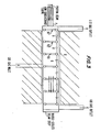
- a target apparatus suitable for the generation of the before-described resonance absorption 9.172 MeV of 14N is illustrated, incorporating the enhancing yield technique of the invention, and employing a proton beam of about 1.75 MeV.
- the target is shown constructed by placing a series of successive self-supporting foils 1-1 ⁇ ⁇ of carbon 13 (13C) in a row -- illustrated as a five-foil system.
- the foils may be constructed as before described, for example, as self-supported evaporated layers mounted on thin rings.
- each foil will cause the impinging protons to lose about 500 volts of energy.
- the 1.75 MeV proton beam will lose about 800 volts of its energy.
- an accelerating or energy-replenishing potential of about 500 volts (or 800 volts for the somewhat thicker foil) is thus supplied across successive foils as shown, then the protons will gain as much energy between successive foils as they lost in collisions in the previous foils, and the protons will stay in resonance.
- the limit to the number of foils that can be used is given by the multiple scattering suffered by the protons. It is estimated that multiple scattering will limit the total target thickness to about 150 ⁇ g/cm2, enabling the use of at least twenty foils and more. If 2 to 3 microgram/cm2 foils are used, then the yield gain may be as high as 50 or 60.
- a weak transverse magnetic field H may be applied, Fig 2, that will not affect the protons, but will bend the electrons into tight spirals so that they do not cause avalanching or other detrimental problems.
- Free-standing foil targets (as opposed to a target evaporated onto a water-cooled metal plate) can be destroyed by heat and radiation damage if the beam currents are too high.
- a 5 ⁇ g/cm2 carbon foil may rupture quickly if exposed to the very high currents of 1.75 reV protons.
- the lifetime of such foils can be increased by one or more of the following techniques: (1) increasing the beam diameter so that the heat and radiation damage are spread over a wider area; (2) cooling the foils by, for example, helium gas; (3) rotating or indexing foils to that individual foils are exposed to the beam only a fraction of the time; or (4) special foil preparation as documented in the literature ( Nuclear Instruments and Methods , North-holland Publishing Co, N.I.M. 167, (1978); 1-8; N.I.M. 200, (1980) 162).
- the amplification gain will be limited by the minimum thickness of robust, free-standing carbon foils. As before described, the thinnest targets presently available are about 3 ug/cm2 thick, though 5ug/cm2 may be more standard. The effective foil thicknesses will generally be greater since the foils have non-uniformities and are purposefully wrinkled to increase their life.
- the maximum amplification gain will be given by the maximum tolerable energy loss divided by the energy lost per foil; for example, about 40 kev/0.8 kev 0 50 -- a number earlier presented.
- Tbe practical problem of making and mounting large numbers of very thin carbon foils made of a highly enriched isotope adds complexity and cost if the foils have to be replaced often. At maximum amplification, perhaps as many as 50 foils may be used at once. Perhaps 10 times that number will be needed for replacement, for example, in a rotating wheel, target cassette. The cost of the system may be high if the foils have to be replaced more frequently than, say, about once a month.
- Windowless gas targets can overcome some of the above-described disadvantages by using either continuous or discrete energy-loss cells with 13C-containing gas.
- Fig. 3 shows the principal elements of a continuous resonance gas target illustrated as a cell G, one meter long, filled with 13C-doped methane (CH4) at a pressure of 1.0 Torr.
- CH4 13C-doped methane
- suitable gases include CO2 and CO.
- the few watts of beam power dissipated in the cell are easily dealt with.
- the windowless gas target can withstand any current that a modern proton beam accelerator can produce. The proton will lose 40 kev on traversing the meter-long cell.
- the amplification factor will be at least 2 and more likely at least 4 times that attainable with a multiple-foil target. This factor may be estimated as follows for the exampled cell of Fig. 3.
- the thickness of the cell can be made 250 ⁇ g/cm2.
- the acceptable energy loss has been taken to be about the same as with a carbon foil target in fact the acceptable energy loss will be significantly greater since methane multiply-scatters less than pure carbon.
- the ideal amplification could be as much as 200; that is, a gain of 4 over the use of foils.
- Gas targets are not, however, without their own problems. There is first the operation of a cell G, Fig. 3, at a pressure of 1-10 Torr, that is connected directly to the main accelerator source of proton beam, typically operated at vacuum pressures of 10 ⁇ 5 Torr or less. Second, is the complication of electrons in the gas that are generated as the proton passes through. Third, is the fact that the successive portions of the target are now spread out over, for example, a meter of length in the example of Fig. 3.
- the low-conductance connection P is illustrated as consisting of several (perhaps a bundle) of long, relatively small diameter tubes that represent a high resistance to the gas flow, while passing the nearly parallel proton beam with very little loss of intensity.
- the closed-loop pump before-mentioned has a condenser kept at a temperature below the liquification point of the gas. Liquid air may be used for the before-described illustrative methane. The gas is liquified as it is pumped by the condensor and is subsequently evaporated for pumping back into the cell at the "Inlet".
- the successive portions of the continuous gas cell target G will be provided with successive voltage boosts V to replace the lost energy in the proton ionization of such successive portions that results in generating the desired gamma rays.
- substantially equal voltages V are introduced by connection between successive films to restore the loss of energy in the proton beam colliding with each successive portion and thereby generating the resonance gamma rays
- similar operation is attained in the gas target of Fig. 3 with the aid of conductive rings R1, R2, R3, etc. defining successive portions of the gas target medium G and between which rings the before-mentioned proton-energy-restoring voltage increments V are supplied.
- the protons lose their energy in the target G primarily by ionizing the gas atoms.
- Each ionization requires about 30 e.v. of energy so that approximately 1200 electrons and positive ions will be created by each proton that passes through the exampled gas cell target; that is, about twelve electron-positive ions per cm.
- the electrons will "see" the accelerating voltage and be attracted to the positive electrode.
- the ions will be attracted by the negative , electrode but are moving slowly and thus present no serious problem.
- the free electrons will accelerate until they too become ionizers of the atoms of ,the target gas. If preventive measures are not taken, accordingly, a plasma of electrons and positive ions will build up with a space charge that effectively can shield the gas cell from the external accelerating potential.
- the cascade is quenched before it begins, by applying an external transverse magnetic field H, so-labelled in Fig. 3, that will prevent the electrons from gaining sufficient energy to ionize.
- An external field of 100 Gauss for example, will cause the low-energy electrons (typical energies are only a few e.v.) to curl up with a small radius of curvature and drift at constant speed through the cell.
- Such a 100 Gauss field H will bend the protons with a radius of curvature of 20 meters which can easily be accommodated in the design. If the bending of the protons becomes a problem -- and it will be if a larger magnetic field is needed to quench an electron produced plasma -- then alternating magnetic fields can be applied along the length of the cell so as to give no net deflection to the proton beam.
- Differentially-pumped gas cells used routinely in nuclear physics in tandem accelerators for the very different purpose of "stripping" electrons off from energetic ions to make those ions more positively charged may be used here as each of the discrete gas cells G1, G2, G3, etc., in an overall system of 50 to 100 cells. In practice, the cell length may be about 1 cm.
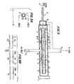
- Fig. 5 illustrates a gas cell accelerator target for 14N gamma ray , resonance absorption in which :the electrons and positive ions, generated in the gas by the incident proton beam, are pulled out of the beam by a low-voltage electrostatic collector in the beam line.
- This embodiment combines the long continuous gas target G of Fig. 3 with the acceleration electric field uniform throughout the length of the target, with the series of separate gas cells G1, G2, G3, etc. of Fig. 4 with the accelerating potentials between each cell, with significant advantages.
- the figure shows the scheme with three cells; but, in practice, the target could have as many as 50; the limit being degradations due to multiple scattering and energy fluctuations.
- Fig. 5 The basic idea of Fig. 5 is to use a single gas beam target line medium that is segmented into a naumber of electrically independent tube portions 1, with the accelerating potentials or compensating V applied between them.
- the continuous target tube requires, in principle, only one gas inlet 13 and one gas outlet 11, thus greatly reducing the pumping requirements on the vacuum system. In practice one may want several inlet lines, but the gain over the previously described system of Fig. 4 seems to be still substantial.
- the "high pressure" targets 1, which might be operated at pressures of about 1 Torr, are isolated from the main photon accelerator 6 by a large volume 12 connected to the high-speed pump and a relatively small diameter beam line 14, that has a high resistance to gas flow.
- the adjacent conductor tube portions 1 are electrically insulated by sealed, non-conducting sleeves 5 which maintain separation gaps 4 so that an electrical potential difference V established between the adjacent tube portions 1 results in an electric accelerating field on the protons passing down the axis of the target.
- the final beam stop 7 is water cooled.
- Each target portion 1 has a length that is several times its diameter, serving thus as an effective Faraday cage, isolated from all external fields.
- a cylindrical metal mesh electrode 3 is shown inserted into each tube portion 1, of diameter larger than that of the proton beam 6 and electrically isolated from the sections 1.
- the cylindrical mesh 3, in turn, is split into electrically isolated halves 3A and 3B, Fig. 5A.
- a voltage is placed across the halves so that electrons and ions, formed in the space 10 are pulled to the positive and negative halves 3A and 3B (+ and -) of the mesh 3 and never get accelerated across the gap 4, between the target portions 1; i.e., providing electrical ion quenching.
- the insulator sleeves 5 can be modified so that the beam sees only conductors.
- FIG. 5B An example of possible voltages is shown in Fig. 5B, with the respective cylindrical mesh grids 3A and 3B having bias voltages of +10 and -10 volts.
- the target portions or segments 1 have 0, -500 volts and -1,000 volts on them giving an acceleration potential of 500 volts across each gap to make up for a proton energy loss of 500 electron volts in successive portions, as earlier described in connection with the embodiments of Figs. 1-4.
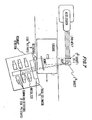
- Fig. 6 shows the basic geometry of the 14N resonance gamma ray cone produced by the 13C-containing targets of Figs. 1-5B over a one -degree angle at 80.5° with respect to the proton beam direction (horizontal in Figs. 1-5), and the appropriate positioning or movement of the luggage L to intercept the same. It is very similar to the familiar X-ray system used to scan luggage in airports; but instead of a fan-beam of X-rays passing through the bags, a narrow cone of precisely the right energy gamma rays is employed passing through collimating slits S and then through the luggage L and into an array of detectors D.
- Nitrogen in the luggage preferentially absorbs these resonant gamma rays, as before explained, causing a dip in the signal strength; the before-described Resonance Absorption Analysis (RAA).
- RAA Resonance Absorption Analysis
- the method is a very sensitive technique for finding nitrogen, and it is capable of spatial resolutions of the order of a cubic inch. It is almost impossible to thwart and it uses no neutrons and makes nothing radioactive.
- the present invention also provides for the resonance absorption method of measuring oxygen in explosives.
- the oxygen concentration is measured by determining the intensity change of 16O resonant gamma rays that are transmitted through the luggage or other container of the suspected explosives and detected this time: by a resonant detector that is sensitive only to such resonant gamma rays.
- the resonant 16O gamma rays are emitted in all directions to the proton beam direction, and require a special resonance absorption detection apparatus in the direction of the passing luggage -- say along the same 80.5° direction.
- the same incident proton beam for RAA of nitrogen may also be employed for RAA of oxygen as shown in Fig. 7.
- the same proton accelerator -- the largest single cost of an RAA sheme -- may be used simultaneously to measure both the oxygen and nitrogen distributions in a piece of luggage or the like.
- the 6.92 MeV and 7.12 MeV states are strongly excited by the reaction: protons + 19 Fl ⁇ 16O* + alpha particle; 16O* ⁇ 16O + 6.92 or 7.12 gamma rays.
- the symbol * means excited.
- the reaction is exoergic by 8.11 MeV so that it proceeds, in principle, for any proton energy above zero; but in practice, the cross section for the reaction is strong for proton energies above about 0.5 MeV.
- the 6.92 and 7.12 MeV gamma rays are produced from an excited oxygen nucleus that is recoiling rapidly due to the momentum given it by the combination of the incident proton and the emitted alpha particle. As a consequence, only a very small fraction of the 6.92 or 7.12 MeV gamma rays will be in resonance with corresponding states in an oxygen target.
- the small fraction of resonant gamma rays produced per reaction is made up for by the large cross section for the production of the gamma rays and by the fact that one can make use of more than 1 MeV of energy loss to create the gamma rays in the system of Fig. 7.
- the combination of these favorable factors makes the production of resonant gamma rays in oxygen about that for the 9.17 MeV gamma ray in 14N.
- the resonant component of 6.92 and 7.12 Mev gamma rays is rather independent of the angle of emission in sharp contrast to the 9.172 MeV gamma rays emitted by 14N in resonance, which, as before stated, occurs only over a 1 degree angle at 80.5° with respect to the beam direction. It is therefore necessary to count the gamma rays with a resonant detector as earlier stated.
- Fig. 7 in addition to the 14N gamma rays produced from target 13C as shown in Fig. 6, the same proton beam is passed to a 19F target.
- the 6.92 and 7.12 MeV gamma rays thus generated are shown penetrating the luggage L and resonantly detected by resonant gamma ray detectors D′, later described.
- the detection is sequential with the luggage passing the 14N gamma rays detected at D and then the 16O gamma rays at D′; but the inverse order, or substantial simultaneity are feasible also.
- a long gamma ray generating gas cell may require counters carefully collimated with lead or tungsten so that each detector "sees" the gamma ray narrow cone from only one slice of the luggage or other object at any given time.
- the long cell type of target before described can be of decided advantage if one uses resonant detectors that respond only to those gamma rays that are precisely in resonance. Such detectors are intrinsically collimated since they only respond to gamma rays that originate at precisely the correct angle from the target.
- Another simple geometry that makes use of resonant detectors surrounding a long gas cell target medium may consist of a tunnel of resonant detectors deployed around the target gas cell (not shown).
- Each array of detectors may contain, for example, 100 detectors, each about 2 cm wide, with their front faces about 1.2 meters from the gas cell. Forty such rings could be used making a total of 4,000 detectors. While the detector/electronics for such a system is expensive (though resonant detectors are inexpensive to make), such a system can be cost effective if it processes about 20 or 30 bags a minute.
- the resonant detector of Fig. 7 is shown comprising a thick collimator TC through which the 6.92 or 7.12 MeV gamma rays at that angle will be passed into a water chamber (H2O) surrounded by gamma ray detectors responsive to the re-emitted resonance gamma rays resulting from absorption in the water, and providing sensitive and amplified detection of these gamma rays, also.
- H2O water chamber
- gaseous compounds for enabling resonance gamma ray generation for both 14N and 16O may be employed; for example, 13CF4 or 13COF2 -- the 13C for the nitrogen and the natural fluorine for the oxygen.
- Appropriate organic fluorocarbons may also be used.
Landscapes
- Physics & Mathematics (AREA)
- High Energy & Nuclear Physics (AREA)
- Plasma & Fusion (AREA)
- Chemical Kinetics & Catalysis (AREA)
- Optics & Photonics (AREA)
- Engineering & Computer Science (AREA)
- Chemical & Material Sciences (AREA)
- Spectroscopy & Molecular Physics (AREA)
- Life Sciences & Earth Sciences (AREA)
- General Life Sciences & Earth Sciences (AREA)
- General Physics & Mathematics (AREA)
- Geophysics (AREA)
- Analysing Materials By The Use Of Radiation (AREA)
- Geophysics And Detection Of Objects (AREA)
Applications Claiming Priority (2)
| Application Number | Priority Date | Filing Date | Title |
|---|---|---|---|
| US518785 | 1983-07-29 | ||
| US07/518,785 US5251240A (en) | 1990-05-04 | 1990-05-04 | Method and apparatus for employing resonance-produced gamma rays to detect the presence of both nitrogen and oxygen in objects that may contain explosives |
Publications (2)
| Publication Number | Publication Date |
|---|---|
| EP0455515A2 true EP0455515A2 (de) | 1991-11-06 |
| EP0455515A3 EP0455515A3 (de) | 1991-12-04 |
Family
ID=24065494
Family Applications (1)
| Application Number | Title | Priority Date | Filing Date |
|---|---|---|---|
| EP19910304058 Withdrawn EP0455515A3 (de) | 1990-05-04 | 1991-05-03 | Vorrichtung zur Erzeugung von Resonanz-Kernreaktionen |
Country Status (5)
| Country | Link |
|---|---|
| US (1) | US5251240A (de) |
| EP (1) | EP0455515A3 (de) |
| JP (1) | JPH05100049A (de) |
| CA (1) | CA2041868A1 (de) |
| IL (1) | IL98064A0 (de) |
Cited By (4)
| Publication number | Priority date | Publication date | Assignee | Title |
|---|---|---|---|---|
| EP0425662A4 (en) * | 1989-05-08 | 1992-08-12 | Scientific Innovations, Inc. | Nuclear resonances in activation analysis, and particularly, its application to detection of nitrogen based explosives in luggage |
| US5323004A (en) * | 1989-05-08 | 1994-06-21 | Scientific Innovations, Inc. | Nuclear resonances in activation analysis, and particularly, its application to detection of nitrogen based explosives in luggage |
| WO1994015199A1 (en) * | 1992-12-22 | 1994-07-07 | THE UNIVERSITY OF ALBERTA, SIMON FRASER UNIVERSITY, THE UNIVERSITY OF VICTORIA, THE UNIVERSITY OF BRITISH COLUMBIA, carrying on as TRIUMF | Nitrogen detector and method of detecting |
| CN1034884C (zh) * | 1992-03-26 | 1997-05-14 | 清华大学 | 爆炸物检测系统 |
Families Citing this family (23)
| Publication number | Priority date | Publication date | Assignee | Title |
|---|---|---|---|---|
| US5631526A (en) * | 1995-05-15 | 1997-05-20 | National Electrostatics Corp. | Hydrogen ion accelerator |
| US5784430A (en) * | 1996-04-16 | 1998-07-21 | Northrop Grumman Corporation | Multiple station gamma ray absorption contraband detection system |
| US5982838A (en) | 1997-03-26 | 1999-11-09 | Western Kentucky University | Method and portable apparatus for the detection of substances by use of neutron irradiation |
| US6215851B1 (en) | 1998-07-22 | 2001-04-10 | Northrop Grumman Corporation | High current proton beam target |
| US6724852B1 (en) * | 2001-03-07 | 2004-04-20 | The United States Of America As Represented By The United States Department Of Energy | Fissile interrogation using gamma rays from oxygen |
| RU2206080C1 (ru) * | 2001-11-08 | 2003-06-10 | Открытое акционерное общество "Научно-технический центр "РАТЭК" | Способ обнаружения взрывчатого вещества в контролируемом предмете |
| US7162005B2 (en) * | 2002-07-19 | 2007-01-09 | Varian Medical Systems Technologies, Inc. | Radiation sources and compact radiation scanning systems |
| US7027555B2 (en) * | 2003-01-15 | 2006-04-11 | Proctor Raymond J | Mineral matter analyzer apparatus and method |
| US7317782B2 (en) * | 2003-01-31 | 2008-01-08 | Varian Medical Systems Technologies, Inc. | Radiation scanning of cargo conveyances at seaports and the like |
| US6954515B2 (en) * | 2003-04-25 | 2005-10-11 | Varian Medical Systems, Inc., | Radiation sources and radiation scanning systems with improved uniformity of radiation intensity |
| US6937692B2 (en) * | 2003-06-06 | 2005-08-30 | Varian Medical Systems Technologies, Inc. | Vehicle mounted inspection systems and methods |
| US8180019B2 (en) | 2003-11-24 | 2012-05-15 | Passport Systems, Inc. | Methods and systems for computer tomography of nuclear isotopes using nuclear resonance fluorescence |
| CA2589047C (en) | 2003-11-24 | 2014-02-11 | Passport Systems, Inc. | Adaptive scanning of materials using nuclear resonance fluorescence imaging |
| IL159406A (en) * | 2003-12-16 | 2013-10-31 | Mark Goldberg | A method and system for detecting materials, such as special nuclear materials |
| WO2005121756A2 (en) * | 2004-06-03 | 2005-12-22 | Brondo Joseph H Jr | Mult-mode gamma beam detection and imaging system |
| US7218706B2 (en) * | 2004-12-20 | 2007-05-15 | General Electric Company | Energy discrimination radiography systems and methods for inspecting industrial components |
| US7501624B1 (en) * | 2005-04-28 | 2009-03-10 | Brookhaven Technology Group, Inc. | System and method for detecting concealed nuclear materials, radiological materials and chemical explosives |
| US7499523B2 (en) * | 2006-08-02 | 2009-03-03 | General Electric Company | Systems and methods for identifying a substance |
| WO2009051697A1 (en) * | 2007-10-12 | 2009-04-23 | Varian Medical Systems, Inc. | Charged particle accelerators, radiation sources, systems, and methods |
| CA2696031C (en) * | 2009-02-10 | 2012-08-21 | Optosecurity Inc. | Method and system for performing x-ray inspection of a product at a security checkpoint using simulation |
| US8687764B2 (en) | 2010-04-14 | 2014-04-01 | Uday S. Roy | Robotic sensor |
| CN115565711A (zh) * | 2022-09-22 | 2023-01-03 | 中国原子能科学研究院 | 一种单能高能伽马源的制备方法 |
| CN116046807A (zh) * | 2022-12-21 | 2023-05-02 | 中国原子能科学研究院 | 一种基于激光的集装箱爆炸物检测系统及方法 |
Family Cites Families (6)
| Publication number | Priority date | Publication date | Assignee | Title |
|---|---|---|---|---|
| US3171961A (en) * | 1960-12-30 | 1965-03-02 | California Research Corp | Nuclear resonance fluorescence logging |
| US3997787A (en) * | 1975-04-25 | 1976-12-14 | Bain Griffith | Apparatus and method for detecting explosives |
| US4756866A (en) * | 1985-10-09 | 1988-07-12 | Alvarez Luis W | Nitrogen detection |
| FR2588969B1 (fr) * | 1985-10-18 | 1988-02-26 | Commissariat Energie Atomique | Dispositif de detection de substances par exemple explosives |
| IL86826A (en) * | 1988-06-22 | 1992-02-16 | Israel Atomic Energy Comm | Method and system for detection of nitrogenous explosive by using nuclear resonance |
| US5040200A (en) * | 1989-05-08 | 1991-08-13 | Scientific Innovations, Inc. | Gamma-gamma resonance in activation analysis, and particularly, its application to detection of nitrogen based explosives in luggage |
-
1990
- 1990-05-04 US US07/518,785 patent/US5251240A/en not_active Expired - Fee Related
-
1991
- 1991-05-03 EP EP19910304058 patent/EP0455515A3/de not_active Withdrawn
- 1991-05-05 IL IL98064A patent/IL98064A0/xx unknown
- 1991-05-06 CA CA002041868A patent/CA2041868A1/en not_active Abandoned
- 1991-05-07 JP JP10163891A patent/JPH05100049A/ja active Pending
Cited By (6)
| Publication number | Priority date | Publication date | Assignee | Title |
|---|---|---|---|---|
| EP0425662A4 (en) * | 1989-05-08 | 1992-08-12 | Scientific Innovations, Inc. | Nuclear resonances in activation analysis, and particularly, its application to detection of nitrogen based explosives in luggage |
| US5293414A (en) * | 1989-05-08 | 1994-03-08 | Scientific Innovations, Inc. | Nuclear resonances in activation analysis, and particularly, its application to detection of nitrogen based explosives in luggage |
| US5323004A (en) * | 1989-05-08 | 1994-06-21 | Scientific Innovations, Inc. | Nuclear resonances in activation analysis, and particularly, its application to detection of nitrogen based explosives in luggage |
| CN1034884C (zh) * | 1992-03-26 | 1997-05-14 | 清华大学 | 爆炸物检测系统 |
| WO1994015199A1 (en) * | 1992-12-22 | 1994-07-07 | THE UNIVERSITY OF ALBERTA, SIMON FRASER UNIVERSITY, THE UNIVERSITY OF VICTORIA, THE UNIVERSITY OF BRITISH COLUMBIA, carrying on as TRIUMF | Nitrogen detector and method of detecting |
| AU669418B2 (en) * | 1992-12-22 | 1996-06-06 | University of Alberta, Simon Fraser University, The University of Victoria, and The University of British Columbia, doing business as Triumf, The | Nitrogen detector and method of detecting |
Also Published As
| Publication number | Publication date |
|---|---|
| CA2041868A1 (en) | 1991-11-05 |
| US5251240A (en) | 1993-10-05 |
| JPH05100049A (ja) | 1993-04-23 |
| EP0455515A3 (de) | 1991-12-04 |
| IL98064A0 (en) | 1992-06-21 |
Similar Documents
| Publication | Publication Date | Title |
|---|---|---|
| US5251240A (en) | Method and apparatus for employing resonance-produced gamma rays to detect the presence of both nitrogen and oxygen in objects that may contain explosives | |
| Koshchiy et al. | ANASEN: The array for nuclear astrophysics and structure with exotic nuclei | |
| Arnaud et al. | Spherical Proportional Counter: A review of recent developments | |
| US7501624B1 (en) | System and method for detecting concealed nuclear materials, radiological materials and chemical explosives | |
| Lee et al. | Thermal neutron analysis (TNA) explosive detection based on electronic neutron generators | |
| Bystritsky et al. | Investigation of temperature dependence of neutron yield and electron screening potential for the d (d, n) 3He reaction proceeding in deuterides ZrD2 and TiD2 | |
| Fisher et al. | Fast alpha diagnostics using pellet injection | |
| Cohen | Anomalous diffusion in a plasma formed from the exhaust beam of an electron-bombardment ion thruster | |
| Brodeur et al. | On-line installation of the superallowed transition beta-neutrino decay ion coincidence trap | |
| Xin et al. | Experimental research on beam current extraction of PIG negative hydrogen ion source for neutron tube | |
| US7596197B1 (en) | Gamma source for active interrogation | |
| Blankstein | Active Target Measurement of the 25, 26Mg (α, n) 28, 29Si Total Cross Section | |
| EP1588593B1 (de) | Codiertes target für eine neutronenquelle | |
| Walker et al. | The acceleration of heavy ions in a fixed-frequency cyclotron | |
| MacMullin | Elastic and inelastic scattering of neutrons from neon and argon: Impact on neutrinoless double-beta decay and dark matter experimental programs | |
| Hamacher-Baumann | Study of electron swarm parameters in argon-based drift gases at high pressures for future neutrino experiments | |
| Bolozdynya | Review of two-phase emission detectors R&D (Dedicated to the memory of Prof. Boris A. Dolgoshein) | |
| Pinfold et al. | Detector for magnetic monopoles at OPAL | |
| Grossmann-Handschin et al. | A radial projection drift chamber using a CO2 iC4H10 gas mixture | |
| Parusov et al. | GEM-Based Detectors for Direct Detection of Low-Mass WIMP, Solar Axions and Narrow Resonances (Quarks) | |
| FURUNO et al. | Missing-mass spectroscopy of short-lived nuclei at low-momentum transfer region opened by the MAIKo active target | |
| Ovchinnikov et al. | GEM-based detectors for direct detection of low-mass WIMP, solar axions and narrow resonances (quarks) | |
| Gastaldi | Spiral projection chambers: experience and prospects | |
| Carter et al. | Search for two-photon emission from 2S states of low-Z muonic atoms | |
| Radchenko et al. | Formation of hydrogen atoms in the 2s and 2p states by neutralization of H-ions in gases |
Legal Events
| Date | Code | Title | Description |
|---|---|---|---|
| PUAI | Public reference made under article 153(3) epc to a published international application that has entered the european phase |
Free format text: ORIGINAL CODE: 0009012 |
|
| PUAL | Search report despatched |
Free format text: ORIGINAL CODE: 0009013 |
|
| AK | Designated contracting states |
Kind code of ref document: A2 Designated state(s): BE CH DE DK ES FR GB GR IT LI NL SE |
|
| AK | Designated contracting states |
Kind code of ref document: A3 Designated state(s): BE CH DE DK ES FR GB GR IT LI NL SE |
|
| 17P | Request for examination filed |
Effective date: 19920601 |
|
| STAA | Information on the status of an ep patent application or granted ep patent |
Free format text: STATUS: THE APPLICATION IS DEEMED TO BE WITHDRAWN |
|
| 18D | Application deemed to be withdrawn |
Effective date: 19941201 |