EP0455531A1 - Verfahren zur Selbstlenkung eines Flugkörpers gegen ein Überschallziel - Google Patents
Verfahren zur Selbstlenkung eines Flugkörpers gegen ein Überschallziel Download PDFInfo
- Publication number
- EP0455531A1 EP0455531A1 EP91401006A EP91401006A EP0455531A1 EP 0455531 A1 EP0455531 A1 EP 0455531A1 EP 91401006 A EP91401006 A EP 91401006A EP 91401006 A EP91401006 A EP 91401006A EP 0455531 A1 EP0455531 A1 EP 0455531A1
- Authority
- EP
- European Patent Office
- Prior art keywords
- missile
- target
- trajectory
- supersonic
- pressure sensors
- Prior art date
- Legal status (The legal status is an assumption and is not a legal conclusion. Google has not performed a legal analysis and makes no representation as to the accuracy of the status listed.)
- Granted
Links
- 238000000034 method Methods 0.000 title claims abstract description 16
- 230000035939 shock Effects 0.000 claims abstract description 21
- 238000005259 measurement Methods 0.000 claims description 5
- 238000010304 firing Methods 0.000 claims description 3
- 238000001514 detection method Methods 0.000 claims description 2
- 230000005284 excitation Effects 0.000 claims description 2
- 230000000737 periodic effect Effects 0.000 claims description 2
- 238000009434 installation Methods 0.000 claims 1
- 229920006395 saturated elastomer Polymers 0.000 claims 1
- 230000001133 acceleration Effects 0.000 description 5
- 230000000694 effects Effects 0.000 description 2
- 210000000056 organ Anatomy 0.000 description 2
- 230000005855 radiation Effects 0.000 description 2
- 230000001052 transient effect Effects 0.000 description 2
- 238000010586 diagram Methods 0.000 description 1
- 230000008520 organization Effects 0.000 description 1
- 230000001902 propagating effect Effects 0.000 description 1
- 230000035945 sensitivity Effects 0.000 description 1
- 230000001960 triggered effect Effects 0.000 description 1
Images



Classifications
-
- F—MECHANICAL ENGINEERING; LIGHTING; HEATING; WEAPONS; BLASTING
- F41—WEAPONS
- F41G—WEAPON SIGHTS; AIMING
- F41G7/00—Direction control systems for self-propelled missiles
- F41G7/20—Direction control systems for self-propelled missiles based on continuous observation of target position
- F41G7/22—Homing guidance systems
- F41G7/2273—Homing guidance systems characterised by the type of waves
- F41G7/228—Homing guidance systems characterised by the type of waves using acoustic waves, e.g. for torpedoes
Definitions
- the present invention relates to a method for homing tactical missiles to a supersonic aim.
- the guided organ of guided missiles is a sensor sensitive to the electromagnetic or infrared radiation of the target.
- This sensor is, in general, carried on a mobile pointing system slaved to the goal called seeker.
- Gyros mounted on the seeker measure the absolute angular speed of the line of sight which is, to the accuracy of the servo, the missile-target line.
- the sensor can also be linked to the missile.
- the absolute angular speed of the missile-target line is obtained by combining the direction of the target relative to the missile, measured by the sensor, and the absolute orientation of the missile measured by an inertial unit.
- the electromagnetic sensor is active or passive, depending on whether or not it emits radiation illuminating the target.
- the guidance law transforms the absolute angular speed of the line of sight into a missile order. It requires knowledge of the target missile radial speed which is either measured or estimated.
- shock wave is used here to define the pressure wave induced over a long distance by a supersonic target, comparable to a thin sheet of revolution, propagating according to the laws of acoustics.
- acoustic wave could be used in an equivalent manner.
- the subject of the invention is therefore a method of guiding a supersonic anti-air missile towards a supersonic target characterized in that it consists in slaving the trajectory of the missile to the shock wave induced at high speed by said target.
- the missile is provided with a rustic inertial unit providing at all times a measurement of its position M, its speed vector V M , its acceleration T M and its reference trihedron T M in an inertial reference trie T O.
- the sensitive guidance member replacing the seeker, consists of one or more pressure sensors placed on board the missile.
- These sensors may consist of one or more orifices distributed over the missile connected to as many pressure detectors, or to a single detector for all of the orifices. These are simple microphone type detectors. These sensors detect and date, thanks to an internal clock, their passage through the shock wave of the target. Taking into account the stiffness of the front of the shock wave of the target, these passages are dated with very great precision. The bandwidth of the sensors is chosen accordingly.
- Figure 1 shows possible locations of sensors 1, 2, 3 installed on board missile 4.
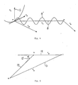
- the order of guidance produces a trajectory of the missile, which, relative to the goal has the appearance of a sinusoid of small amplitude located alternately inside and outside the conical sheet by following a generator of this tablecloth.
- the measurements contributing to the development of the order are carried out at each crossing of the conical sheet. Interception takes place when the missile arrives at the top of the cone which obviously requires that its speed be higher than that of the target.
- FIG. 2 shows the target 5, the absolute trajectory 6 of the target, the missile 4, the conical shock wave 7 of the target 5, the average relative trajectory 8 of the missile 5 which is a generator of the cone, the absolute trajectory average 9 of the missile leading to the interception point 10.
- the guidance law comprises two functional modules programmed on the missile computer.
- the first called the estimator, determines the speed of the missile relatively to the conical tablecloth at each crossing of it.
- the second called the controller, develops the missile command according to the estimated relative speed.
- the estimator estimates the trajectory of the target defined by its position B and its speed vector V B , ie in all six parameters, from the successive positions of the pressure sensors M C (k, i) at the crossing of the wave shock (k the number of the sensor, i number of the crossing), occurring at the instant . These positions are deducted from the position at the missile developed by the inertial unit and the arrangement of the sensors in the missile.
- the controller prepares the orders ordered with the missile.
- the missile to which the invention applies can have any organization. It can be stabilized in roll or in natural autorotation. Its lateral movement can be produced by aerodynamic and / or pyrotechnic forces. The taking of incidence can be caused by an aerodynamic (control), pyrotechnic (impeller, transverse jet) or other actuator.
- the actuator can operate along two transverse axes of maneuver (yaw, pitch) or only one (if the missile is directly in autorotation).
- the command ordered can be addressed directly to the actuator (s) or to an autopilot, if it exists. It can be an autopilot under acceleration or transverse angular velocity. The following presentation is made by assuming a missile stabilized in roll and equipped with an autopilot in acceleration.
- the accelerated missile orders are first calculated in the reference frame x c , y c , z c . They have two components.
- the function f is chosen, in conjunction with the amplitude ⁇ max of the command and the dynamics of the missile, to adjust the amplitude and the frequency of the limit cycle as appropriate.
- the passage distance is of the order of the amplitude of this cycle.
- the acceleration orders are then calculated in the missile coordinate system x m y m , z m (measured by the inertial unit), on the condition that their projections on y c and z c are respectively equal to ⁇ yc and ⁇ zc ,
- FIG. 3 constitutes a simplified functional diagram of the method according to the invention showing the functions exercised by the sensor (s) (function A), the inertial unit (function B), the estimator (functions C) and the controller (functions D).
- FIG. 4 shows the relative trajectory 8 ′ of the missile around the cone generator 8 contained in the plane defined by this generator 8 and the normal 11.
- the missile is launched from a firing station.
- the invention applies to a land, naval or air fire station.
- the launching direction can be arbitrary under the conditions that the missile rallies the shock wave of the target and has sufficient kinematic capacities to enslave itself there and catch up with the target.
- the missile is slaved to a precalculated rallying trajectory under the criterion that the speed of the missile relative to the goal at the first crossing of the the shock wave has a direction as close as possible to that of the generatrix of the conical sheet, that is to say that the kinematic condition of interception indicated in FIG. 5 is fulfilled.
- FIG. 6 shows a complete relative trajectory of interception for a shooting station located inside the conical sheet, which could be the case of an air-air shooting. We see the target 5, its shock wave 7, the relative rallying trajectory 16 and the relative interception trajectory 17.
Landscapes
- Engineering & Computer Science (AREA)
- Physics & Mathematics (AREA)
- Acoustics & Sound (AREA)
- Chemical & Material Sciences (AREA)
- Combustion & Propulsion (AREA)
- General Engineering & Computer Science (AREA)
- Aiming, Guidance, Guns With A Light Source, Armor, Camouflage, And Targets (AREA)
Applications Claiming Priority (2)
| Application Number | Priority Date | Filing Date | Title |
|---|---|---|---|
| FR9005305A FR2661245B1 (fr) | 1990-04-23 | 1990-04-23 | Procede d'autoguidage d'un missile supersonique sur une cible supersonique comportant les dispositions de mise en óoeuvre et les modalites d'utilisation du procede. |
| FR9005305 | 1990-04-23 |
Publications (2)
| Publication Number | Publication Date |
|---|---|
| EP0455531A1 true EP0455531A1 (de) | 1991-11-06 |
| EP0455531B1 EP0455531B1 (de) | 1995-02-22 |
Family
ID=9396100
Family Applications (1)
| Application Number | Title | Priority Date | Filing Date |
|---|---|---|---|
| EP19910401006 Expired - Lifetime EP0455531B1 (de) | 1990-04-23 | 1991-04-16 | Verfahren zur Selbstlenkung eines Flugkörpers gegen ein Überschallziel |
Country Status (3)
| Country | Link |
|---|---|
| EP (1) | EP0455531B1 (de) |
| DE (1) | DE69107508T2 (de) |
| FR (1) | FR2661245B1 (de) |
Cited By (2)
| Publication number | Priority date | Publication date | Assignee | Title |
|---|---|---|---|---|
| US6563763B2 (en) * | 2001-04-03 | 2003-05-13 | Aai Corporation | Method and system for correcting for curvature in determining the trajectory of a projectile |
| CN109596019A (zh) * | 2018-12-19 | 2019-04-09 | 中国空气动力研究与发展中心超高速空气动力研究所 | 一种弹丸飞行速度和轨迹的测量装置及测量方法 |
Citations (6)
| Publication number | Priority date | Publication date | Assignee | Title |
|---|---|---|---|---|
| DE915790C (de) * | 1943-12-03 | 1954-07-29 | Otto Nitzschke | Verfahren und Vorrichtung zum Zuenden von Geschossen |
| US3678453A (en) * | 1970-10-23 | 1972-07-18 | Us Army | Flush mounted acoustic sensor |
| DE3334758A1 (de) * | 1983-09-26 | 1985-04-18 | Bundesrepublik Deutschland, vertreten durch den Bundesminister der Verteidigung, dieser vertreten durch den Präsidenten des Bundesamtes für Wehrtechnik und Beschaffung, 5400 Koblenz | Hubschrauberbekaempfungsverfahren mit lenkflugkoerper |
| EP0157397A2 (de) * | 1984-04-03 | 1985-10-09 | DRELLO, Ing. Paul Drewell GmbH & Co. KG | Anordnung zur Ermittlung der Trefferlage und/oder der Geschwindigkeit und/oder des Auftreffwinkels von mit Überschallgeschwindigkeit auf ein Ziel treffenden Geschossen |
| DE3528075A1 (de) * | 1985-08-05 | 1987-02-12 | Ingbuero Fuer Elektro Mechanis | Verfahren und einrichtung zur stereoakustischen trefferablagemessung von geschossen |
| DE3535575C1 (en) * | 1985-10-05 | 1989-11-23 | Licentia Gmbh | Fuze sensor for a projectile mine, and a method for use of the detonating sensor |
-
1990
- 1990-04-23 FR FR9005305A patent/FR2661245B1/fr not_active Expired - Fee Related
-
1991
- 1991-04-16 EP EP19910401006 patent/EP0455531B1/de not_active Expired - Lifetime
- 1991-04-16 DE DE1991607508 patent/DE69107508T2/de not_active Expired - Fee Related
Patent Citations (6)
| Publication number | Priority date | Publication date | Assignee | Title |
|---|---|---|---|---|
| DE915790C (de) * | 1943-12-03 | 1954-07-29 | Otto Nitzschke | Verfahren und Vorrichtung zum Zuenden von Geschossen |
| US3678453A (en) * | 1970-10-23 | 1972-07-18 | Us Army | Flush mounted acoustic sensor |
| DE3334758A1 (de) * | 1983-09-26 | 1985-04-18 | Bundesrepublik Deutschland, vertreten durch den Bundesminister der Verteidigung, dieser vertreten durch den Präsidenten des Bundesamtes für Wehrtechnik und Beschaffung, 5400 Koblenz | Hubschrauberbekaempfungsverfahren mit lenkflugkoerper |
| EP0157397A2 (de) * | 1984-04-03 | 1985-10-09 | DRELLO, Ing. Paul Drewell GmbH & Co. KG | Anordnung zur Ermittlung der Trefferlage und/oder der Geschwindigkeit und/oder des Auftreffwinkels von mit Überschallgeschwindigkeit auf ein Ziel treffenden Geschossen |
| DE3528075A1 (de) * | 1985-08-05 | 1987-02-12 | Ingbuero Fuer Elektro Mechanis | Verfahren und einrichtung zur stereoakustischen trefferablagemessung von geschossen |
| DE3535575C1 (en) * | 1985-10-05 | 1989-11-23 | Licentia Gmbh | Fuze sensor for a projectile mine, and a method for use of the detonating sensor |
Cited By (2)
| Publication number | Priority date | Publication date | Assignee | Title |
|---|---|---|---|---|
| US6563763B2 (en) * | 2001-04-03 | 2003-05-13 | Aai Corporation | Method and system for correcting for curvature in determining the trajectory of a projectile |
| CN109596019A (zh) * | 2018-12-19 | 2019-04-09 | 中国空气动力研究与发展中心超高速空气动力研究所 | 一种弹丸飞行速度和轨迹的测量装置及测量方法 |
Also Published As
| Publication number | Publication date |
|---|---|
| FR2661245B1 (fr) | 1994-07-29 |
| EP0455531B1 (de) | 1995-02-22 |
| FR2661245A1 (fr) | 1991-10-25 |
| DE69107508D1 (de) | 1995-03-30 |
| DE69107508T2 (de) | 1995-06-14 |
Similar Documents
| Publication | Publication Date | Title |
|---|---|---|
| FR2722579A1 (fr) | Dispositif de correction de trajectoire de missiles | |
| Waldmann | Line-of-sight rate estimation and linearizing control of an imaging seeker in a tactical missile guided by proportional navigation | |
| EP0485292B1 (de) | Optische Vorrichtung zum Messen des Rollwinkels eines Projektils | |
| US8047070B2 (en) | Fast response projectile roll estimator | |
| EP0684485A1 (de) | Verfahren und System zur Positionsbestimmung einer Schusswaffe mittels einer akustischer Detektion | |
| US20030234349A1 (en) | Laser warning systems and methods | |
| FR2719659A1 (fr) | Procédé et dispositif de correction de la trajectoire de projectiles. | |
| WO2014044928A1 (fr) | Ecartomètre à imagerie infrarouge et système de visée et de poursuite automatigue de cible | |
| JPH04110600A (ja) | 軽量ミサイル誘導システム | |
| EP0437126B1 (de) | Leitdatenübertragungssystem für optoelektronische Fernlenkprojektile | |
| FR2483067A1 (fr) | Procede et dispositif destines a eviter des coups defectueux d'appareils de tir automatiques | |
| EP0455531B1 (de) | Verfahren zur Selbstlenkung eines Flugkörpers gegen ein Überschallziel | |
| IL319569A (en) | Systems and methods for estimating the location of a launched projectile | |
| FR2743622A1 (fr) | Engin de simulation destine a detourner des missiles teleguides autodirecteurs | |
| FR2859782A1 (fr) | Systemes d'armes | |
| EP2518433B1 (de) | Verfahren zur automatischen Steuerung eines Zielsuchkopfes, der auf einem Fluggerät montiert ist, insbesondere auf einem Marschflugkörper | |
| EP0169758B1 (de) | Verfahren und Vorrichtung zur Bestimmung der Ortung eines Objektes im Raum und Anwendung bei der Schusssimulation | |
| EP1096219A1 (de) | Verfahren und System zur Entdeckung einer nach einem festen oder beweglichen Gegenstand geworfenen Bedrohung | |
| FR2640043A1 (fr) | Procede de reconnaissance de cible pour engins volants comportant une tete chercheuse | |
| EP0420760B1 (de) | Selbstlenkungssystem und -verfahren einer getriebenen ballistischen Luftfahrzeuggeschosses gegen ein Ziel | |
| FR2748814A1 (fr) | Dispositif de determination de l'orientation en roulis d'un engin volant, notamment d'une munition | |
| EP1866597B1 (de) | System zur zielbestimmung und/oder -beleuchtung und für die luftaufklärung | |
| EP0650026B1 (de) | Verfahren zum Betrieb eines im Vergleich zum Zielerfassungssystem versetzten Waltensystems und Gesamtheit dieser Systeme zur Durchführung des Verfahrens | |
| FR2463909A1 (fr) | Procede de pilotage et de guidage d'un missile, et missile equipe de moyens de mise en oeuvre de ce procede | |
| JP2000065565A (ja) | 回転飛翔体の回転角計測装置及びその計測方法 |
Legal Events
| Date | Code | Title | Description |
|---|---|---|---|
| PUAI | Public reference made under article 153(3) epc to a published international application that has entered the european phase |
Free format text: ORIGINAL CODE: 0009012 |
|
| AK | Designated contracting states |
Kind code of ref document: A1 Designated state(s): CH DE GB IT LI NL SE |
|
| 17P | Request for examination filed |
Effective date: 19920418 |
|
| 17Q | First examination report despatched |
Effective date: 19940216 |
|
| RAP1 | Party data changed (applicant data changed or rights of an application transferred) |
Owner name: STERIA |
|
| GRAA | (expected) grant |
Free format text: ORIGINAL CODE: 0009210 |
|
| ITF | It: translation for a ep patent filed | ||
| AK | Designated contracting states |
Kind code of ref document: B1 Designated state(s): CH DE GB IT LI NL SE |
|
| PG25 | Lapsed in a contracting state [announced via postgrant information from national office to epo] |
Ref country code: NL Free format text: LAPSE BECAUSE OF NON-PAYMENT OF DUE FEES Effective date: 19950222 |
|
| REF | Corresponds to: |
Ref document number: 69107508 Country of ref document: DE Date of ref document: 19950330 |
|
| GBT | Gb: translation of ep patent filed (gb section 77(6)(a)/1977) |
Effective date: 19950302 |
|
| PG25 | Lapsed in a contracting state [announced via postgrant information from national office to epo] |
Ref country code: SE Effective date: 19950522 |
|
| NLV1 | Nl: lapsed or annulled due to failure to fulfill the requirements of art. 29p and 29m of the patents act | ||
| PLBE | No opposition filed within time limit |
Free format text: ORIGINAL CODE: 0009261 |
|
| STAA | Information on the status of an ep patent application or granted ep patent |
Free format text: STATUS: NO OPPOSITION FILED WITHIN TIME LIMIT |
|
| 26N | No opposition filed | ||
| PGFP | Annual fee paid to national office [announced via postgrant information from national office to epo] |
Ref country code: CH Payment date: 19970505 Year of fee payment: 7 |
|
| PGFP | Annual fee paid to national office [announced via postgrant information from national office to epo] |
Ref country code: GB Payment date: 19980416 Year of fee payment: 8 |
|
| PG25 | Lapsed in a contracting state [announced via postgrant information from national office to epo] |
Ref country code: LI Free format text: LAPSE BECAUSE OF NON-PAYMENT OF DUE FEES Effective date: 19980430 Ref country code: CH Free format text: LAPSE BECAUSE OF NON-PAYMENT OF DUE FEES Effective date: 19980430 |
|
| REG | Reference to a national code |
Ref country code: CH Ref legal event code: PL |
|
| PG25 | Lapsed in a contracting state [announced via postgrant information from national office to epo] |
Ref country code: GB Free format text: LAPSE BECAUSE OF NON-PAYMENT OF DUE FEES Effective date: 19990416 |
|
| GBPC | Gb: european patent ceased through non-payment of renewal fee |
Effective date: 19990416 |
|
| PG25 | Lapsed in a contracting state [announced via postgrant information from national office to epo] |
Ref country code: IT Free format text: LAPSE BECAUSE OF NON-PAYMENT OF DUE FEES Effective date: 20050416 |
|
| PGFP | Annual fee paid to national office [announced via postgrant information from national office to epo] |
Ref country code: DE Payment date: 20050510 Year of fee payment: 15 |
|
| PG25 | Lapsed in a contracting state [announced via postgrant information from national office to epo] |
Ref country code: DE Free format text: LAPSE BECAUSE OF NON-PAYMENT OF DUE FEES Effective date: 20061101 |